Hey everyone,
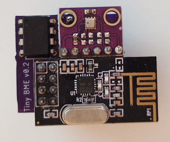
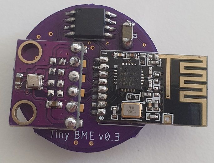
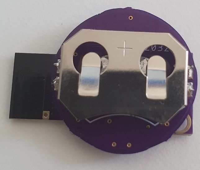
I want to share my tiny BME280 temperature/humidity/pressure sensor node, running on a ATtiny85 and sending messages via a standard nRF24L01+ module.
Background:
I wanted to build a sensor node using standard modules/components and requiring as little space as possible. Also battery powered was mandatory, with a lifetime of about 1 year. So I was looking into ATtiny85 and nRF24L01+ compatibility and found out there where a few nRF libraries that support ATtiny. I also stumbled over the MySensors project and was astonished on how much hardware it supported (especially on the transport layer). I have SX1278/RFM95 modules but I saw that it requires more code memory space (ATtiny only has 8K) so the choice fell on the nRF24L01+.
As for the temperature sensor, the choice fell on Bosch's BME280, since it is one of a few with an SPI interface and I basically have only one pin left on the MCU (well, normally there is no pin left, but I'll explain later). I could have used an DS18B20 or DHT22 (1-Wire) sensor, but in my opinion either the housing is to big (DHT22 module) or the range of functions was inferior to the Bosch sensor (functionality/space). I also know, that using SMD parts would have made this project even more smaller but I don't have a reflow oven and currently don't intent to buy one.
Originally, I was hoping someone already did an ATtiny with MySensors, but searching the Forum for ATtiny support only got me mentions that it would require much code adjustments and got only little stability and also these replies where a couple of years old. I never worked with the MySensor platform before, but I really like the idea of it and the way it is implemented (lightweight, code quality, stability, compatibility to hardware). Also, the runtime is far more enhanced than standard Arduino. So I thought lets give it a try.
It turned out, that as today (which is the 2.3.1 branch of the project), only a few register redefinitions and removing an unused debug function was necessary to get the code compiled and the system running. Of course, much functionality has to be disabled in order to match the 8K ROM of the MCU and also get a BME sensor library running. So there is no debug functionality (only debug over the air, as soon as it was working) and the system runs as passive node (no ACK of messages). But it was running on a breadboard for a couple of weeks without major problems, current consumption in power down was great (~7uA). I'm using a CR2032 battery.
Next step was to build a custom PCB, since wiring all together on such tiny space was too complicated and error prone and ordered at OSH Park (btw, great for small PCBs). Soldering all parts together I noticed two things:
- A design flaw regarding the position of the nRF module. The PCB antenna is overlapping the base PCB and therefore some (!) nRF module are having troubles sending data over the air. What helps it to amend the antenna characteristics like touching the module with a finger or soldering an additional piece of metal to extend the antenna.
- The decoupling capacitor is not necessary and can be left out.
So this is the current state of this project. The modules are running since a couple of months without any further problems, publishing every 2 minutes (or so, +/-10%, since I didn't calibrate the ATtiny) the current temperature, humidity and pressure values as well as the internal VCC voltage value (current battery voltage under load). I'm using a RasPi4 as gateway, running a mosquitto MQTT broker and home-assistant controller.
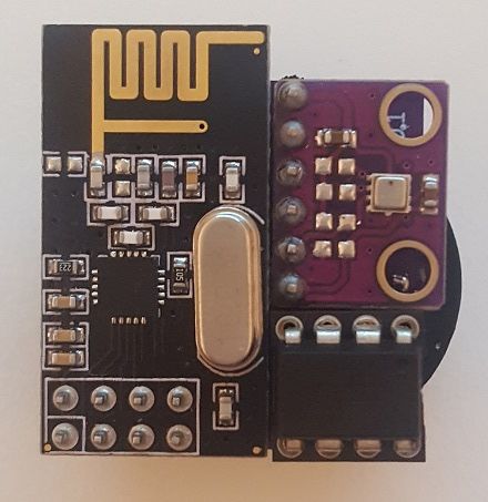
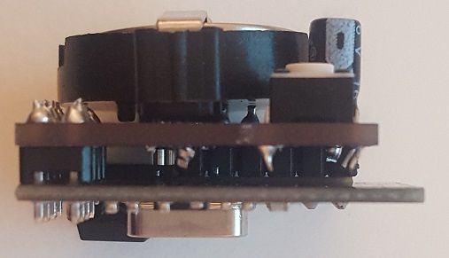
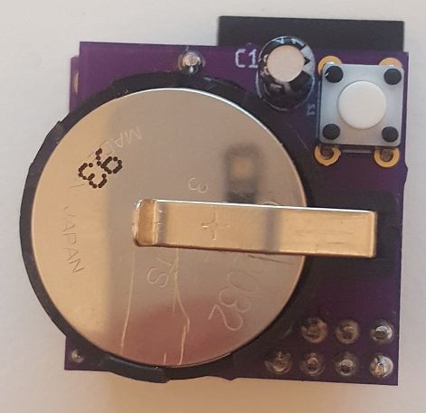
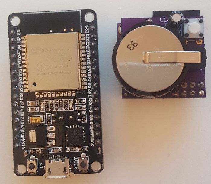
The last picture shows an ESP32 module in comparison.
Hardware
Components:
- ATtiny85 (ATTINY 85-20 PU DIP-8)
- nRF24L01+ (SMD antenna module)
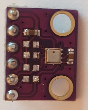
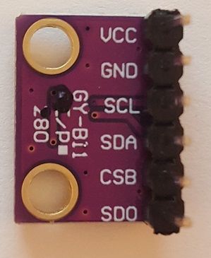
- BME280
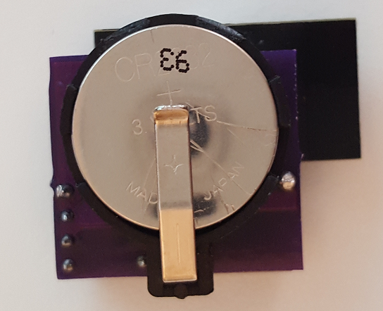
- CR2032
- optionally: reset button switch and 10K resistor
- optionally: decoupling capacitor 47uF
- optionally: DIP-8 socket in order to adjust the firmware
Size:
29mm x 29mm x 19mm (l/w/h)
Current consumption:
Measurements of the current consumption were done with a commercial multimeter.
In power down state, the consumption is ~7uA, in transmit state about 20-25mA. With a duty cycle of 2 minutes this gives a mean of about 20uA and a CR2032 (~200mAh) should work for 1 year.
To get an extra free pin on the MCU, I connected the CE pin of the nRF to high (VCC/VBat). This requires a bit of software adjustments.
The reset of optional and since the power supply from the battery can easily be disconnected this switch is not required.
I'm using a GP Lithium CR2032, with that I don't have issues not using a decoupling capacitor. This also makes a module reset more easy.
The module in the pictures have a DIP-8 socket in order to program the MCU after PCB soldering.
Software
MySensors
As mentioned above, I had to make small modifications to the MySensors platform. These changes are on my fork on Github
- Connecting the CE pin to high, requires a state change of the nRF to Power Down when calling start/stopListening. See nRF24L01+ datasheet Figure 3: Radio control state diagram.
- I had to disable the hwCPUFrequency function, because multiple timer registers are required that are not available on the ATtiny. This function is only used in debug compile mode, so it is not needed for this project.
BME280 sensor library
A very small sensor library is required to match the 8K ROM requirement. After testing different libraries I decided to fork SparkFun's implementation and modify it so that only fixed point calculations are used (instead of floating point). Additionally, the communication method (SPI or I2C) has to be predefined and thus the compiler and linker are able to optimize the code size.
Here is the Github project: Tiny_BME280_Arduino_Library
main.cpp (Arduino Sketch)
I'm working with PlatformIO, but this should also work as Arduino Sketch.
- missing defines
#define SIGRD   RSIG    // Signature Row from Store Program Memory Control and Status Register
#define EIFR    GIFR    // External/General Interrupt Flag Register
#define WDTCSR  WDTCR   // WDT Control Register
// #define TCCR1A TCCR1 // optional
// #define TIFR1 TIFR	// optional
extern void serialEventRun(void) __attribute__((weak));
- Disable Features
#define MY_SPLASH_SCREEN_DISABLED
#define MY_DISABLE_RAM_ROUTING_TABLE_FEATURE
#define MY_DISABLED_SERIAL

#define MY_NODE_ID          20
#define MY_PASSIVE_NODE
#define MY_DISABLE_REMOTE_RESET
- Transport Configuration
#define MY_RADIO_RF24
#define MY_RF24_CE_PIN      NOT_A_PIN
#define MY_RF24_CS_PIN      4
As you can see, I configured the CE pin as NOT_A_PIN. This way, later in software the special handling for start/stopListening can be implemented.
The code size is:
DATA:    [=======   ]  66.2% (used 339 bytes from 512 bytes)
PROGRAM: [==========]  98.2% (used 8048 bytes from 8192 bytes)
This brings one unfortunate limitation: There is absolutely no space for floating point calculations. So, I decided to send the environmental values as fixed point integer and later convert these values on the the controller side to the real values.
Sensor Values
Here is summary of 1 week:
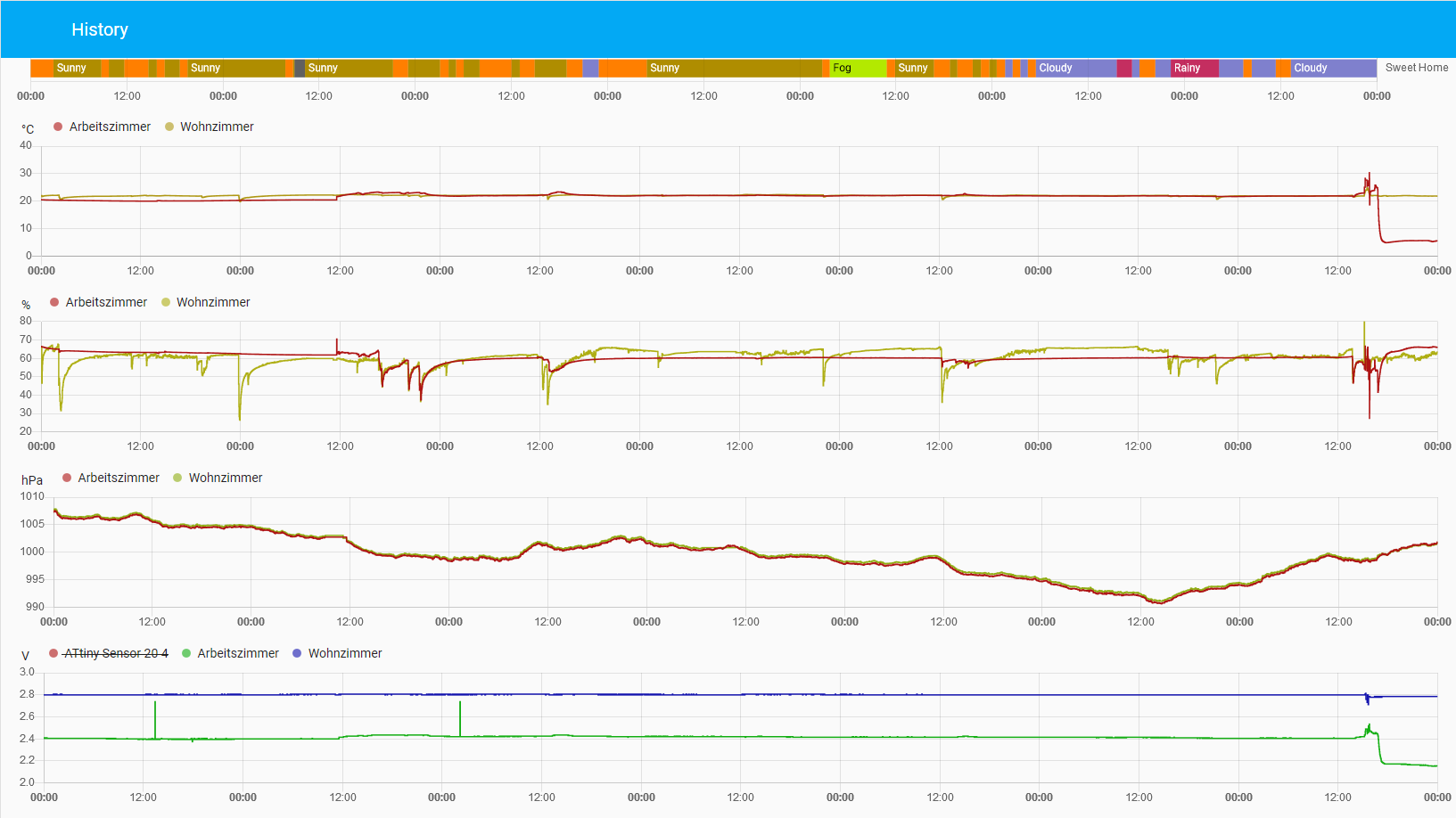
The last line shows the battery voltages. These values are quite stable and I'm satisfied with it. At the end of this week, I put one sensor in the garden outside, thus the drop of the temperature and voltage.
Outlook
The PCB will be revised so that the PCB antenna is free from disturbances. I'm considering to use an ATtiny in SMD package, but this will be probably after the revision.
I also want to provide my changes on the MySensors project into the main branch in order for the project to support ATtiny hardware. Please give me a hint on if and how this should be done.
Feel free to ask if you have any questions! :)
Thanks and Regards
Edit: Fixed current consumption values

