Navigation

    • Register
    • Login
    • OpenHardware.io
    • Categories
    • Recent
    • Tags
    • Popular
    1. Home
    2. freynder
    3. Best
    • Profile
    • Following
    • Followers
    • Topics
    • Posts
    • Best
    • Groups

    Best posts made by freynder

    • Using state machines for MySensors sketch

      As I have been struggling in the past to coordinate states in my sketches, I recently started using state machines. I'm very happy with the result and thought I might share it here should anyone feel interested.

      The code can be found here:
      https://github.com/freynder/LowPowerButtons

      It uses the Automaton library as a framework to run the state machine logic and let the machines interact.
      https://github.com/tinkerspy/Automaton
      There is a small learning curve but I think it's worth it.

      The example sketch consists of a binary switch sensor that uses 2 state machines:

      • SleepyMachine: Will remain awake during a short time and try to detect any button presses. When a timeout is reached it will turn the device into sleep mode. When waking up it will try to find out why and if a button may have been pressed, it will wait for the button to be handled or return to sleep after a short timeout.
      • MySensorsSender: contains logic to send MySenors messages and handle acknowledgement + implements a retry mechanism with timeouts. The retry mechanism is probably redundant as RFM69 performs retries on the transport level already, but it is available should you want it.
      • Button (provided by the framework): handles button presses and debounce logic.

      All the sketch logic is contained within the state machine logic and their interactions; the main loop is very minimal.

      I also used state machines in another node for eliminating doubles while handling RF communications, I can share that as well if interested.

      posted in Development
      freynder
      freynder
    • RE: 💬 E73-2G4M04S Breakout

      Boards arrived today. They look good and initial testing is succesful.

      posted in OpenHardware.io
      freynder
      freynder
    • RE: Pin Change Interrupt on "any" pin.

      @DavidZH

      I have been working on a similar problem lately and just noticed your post. I also tried using libraries at first, but ran into issues due to bouncing signals from the buttons. The pin change interrupt service routine tried to detect which button was pressed, but since the signal was bouncing, button presses were missed. The system would wake up but not call the appropriate callback function associated with the pin.

      I put together a sketch that works for me. It involves setting up the change pin interrupts, detecting which button is pressed and some provisions for debouncing the signal. It uses a small hack to leave the timed sleep function on pin change interrupts. I did not have trouble entering sleep like you did.

      Please note that this sketch uses the current MySensors development branch.

      The sketch is below, I hope it helps.

      /**
       * The MySensors Arduino library handles the wireless radio link and protocol
       * between your home built sensors/actuators and HA controller of choice.
       * The sensors forms a self healing radio network with optional repeaters. Each
       * repeater and gateway builds a routing tables in EEPROM which keeps track of the
       * network topology allowing messages to be routed to nodes.
       *
       * Created by Henrik Ekblad <henrik.ekblad@mysensors.org>
       * Copyright (C) 2013-2015 Sensnology AB
       * Full contributor list: https://github.com/mysensors/Arduino/graphs/contributors
       *
       * Documentation: http://www.mysensors.org
       * Support Forum: http://forum.mysensors.org
       *
       * This program is free software; you can redistribute it and/or
       * modify it under the terms of the GNU General Public License
       * version 2 as published by the Free Software Foundation.
       *
       *******************************
       *
       * DESCRIPTION
       *
       * Interrupt driven binary switch example with dual pin change interrupts
       * Author: Francis Reynders
       * MySensors does not support pin change interrupts currently. This sketch
       * initializes pin change interrupts and combines it with MySensors sleep
       * functions. Some hacking is required to get out of the hwInternalSleep loop.
       * Tested with atmega328p standalone but should work with Arduino Nano/Pro MiniCore
       * Uses RFM69 for transport.
       *
       * Based on original work by:
       * Author: Patrick 'Anticimex' Fallberg
       * Connect one button or door/window reed switch between
       * digitial I/O pin 3 (BUTTON_PIN below) and GND and the other
       * one in similar fashion on digital I/O pin 2.
       * This example is designed to fit Arduino Nano/Pro Mini
       *
       */
      
      // Enable debug prints to serial monitor
      #define MY_DEBUG
      
      // Enable and select radio type attached
      //#define MY_RADIO_NRF24
      #define MY_RADIO_RFM69
      #define MY_RFM69_ENABLE_ENCRYPTION
      #define MY_RFM69_FREQUENCY RF69_433MHZ // Set your frequency here
      //#define MY_IS_RFM69HW // Omit if your RFM is not "H"
      //#define MY_RFM69_NETWORKID 100  // Default is 100 in lib. Uncomment it and set your preferred network id if needed
      #define MY_RF69_IRQ_PIN 2
      #define MY_RF69_IRQ_NUM 0
      #define MY_RF69_SPI_CS 10
      //#define MY_NODE_ID 2
      
      #include <MySensors.h>
      
      #define SKETCH_NAME "Binary Sensor"
      #define SKETCH_MAJOR_VER "2"
      #define SKETCH_MINOR_VER "0"
      
      #define PRIMARY_CHILD_ID 3 // PD3
      #define SECONDARY_CHILD_ID 4 // PD4
      
      #define PRIMARY_BUTTON_PIN 3   // Arduino Digital I/O pin for button/reed switch
      #define SECONDARY_BUTTON_PIN 4 // Arduino Digital I/O pin for button/reed switch
      
      #define DEBOUNCE_INTERVAL 100
      #define DEBOUNCE_COUNT_THRESHOLD 15 // required consecutive positive readings
      #define PREVENT_DOUBLE_INTERVAL 400
      
      #define SLEEP_TIME (6 * 60 * 60 * 1000ul) // Check battery every 6 hours
      
      #define BATTERY_MAX_MVOLT 2900
      #define BATTERY_MIN_MVOLT 2300
      
      // Change to V_LIGHT if you use S_LIGHT in presentation below
      MyMessage msg(PRIMARY_CHILD_ID, V_LIGHT);
      MyMessage msg2(SECONDARY_CHILD_ID, V_LIGHT);
      
      bool triggered = false;
      uint32_t lastWakeup = 0;
      uint16_t lastBatteryVoltage = 0u;
      
      enum wakeup_t {
        WAKE_BY_TIMER,
        WAKE_BY_PCINT0,
        WAKE_BY_PCINT1,
        WAKE_BY_PCINT2,
        UNDEFINED
      };
      
      volatile wakeup_t wakeupReason = UNDEFINED;
      
      // Pin change interrupt service routines
      ISR (PCINT0_vect) // handle pin change interrupt for PCINT[7:0]
      {
        wakeupReason = WAKE_BY_PCINT0;
        _wokeUpByInterrupt = 0xFE; // Dirty hack to get out of MySensors sleep loop
      }
      
      ISR (PCINT1_vect) // handle pin change interrupt for PCINT[14:8]
      {
        wakeupReason = WAKE_BY_PCINT1;
        _wokeUpByInterrupt = 0xFE; // Dirty hack to get out of MySensors sleep loop
      }
      
      ISR (PCINT2_vect) // handle pin change interrupt for PCINT[23:16]
      {
        wakeupReason = WAKE_BY_PCINT2;
        _wokeUpByInterrupt = 0xFE; // Dirty hack to get out of MySensors sleep loop
      }
      
      void pciSetup(byte pin)
      {
        *digitalPinToPCMSK(pin) |= bit (digitalPinToPCMSKbit(pin));  // enable pin
        PCIFR  |= bit (digitalPinToPCICRbit(pin)); // clear any outstanding interrupt
        PCICR  |= bit (digitalPinToPCICRbit(pin)); // enable interrupt for the group
      }
      
      void setup()
      {
        CORE_DEBUG(PSTR("Started\n"));
      
        // Workaround to use center frequency
        //_radio.setFrequency(RF69_EXACT_FREQ);
        #ifdef MY_IS_RFM69HW
          _radio.setPowerLevel(16); // 10dBm for RFM69HW
        #else
          _radio.setPowerLevel(28); // 10dBm for RFM69W
        #endif
      
        pinMode(PRIMARY_BUTTON_PIN, INPUT);           // set pin to input
        digitalWrite(PRIMARY_BUTTON_PIN, INPUT_PULLUP);       // turn on pullup resistors
      
        pinMode(SECONDARY_BUTTON_PIN, INPUT);           // set pin to input
        digitalWrite(SECONDARY_BUTTON_PIN, INPUT_PULLUP);       // turn on pullup resistors
      
        // Set up Pin change interrupt
        pciSetup(PRIMARY_BUTTON_PIN);
        pciSetup(SECONDARY_BUTTON_PIN);
      }
      
      void presentation()
      {
      	// Send the sketch version information to the gateway and Controller
      	sendSketchInfo(SKETCH_NAME, SKETCH_MAJOR_VER "." SKETCH_MINOR_VER);
      
      	// Register binary input sensor to sensor_node (they will be created as child devices)
      	// You can use S_DOOR, S_MOTION or S_LIGHT here depending on your usage.
      	// If S_LIGHT is used, remember to update variable type you send in. See "msg" above.
      	present(PRIMARY_CHILD_ID, S_LIGHT);
      	present(SECONDARY_CHILD_ID, S_LIGHT);
      }
      
      void loop()
      {
        // Unset value from dirty hack to get out of sleep loop (set in interrupt)
        _wokeUpByInterrupt = INVALID_INTERRUPT_NUM;
      
        CORE_DEBUG(PSTR("Woken up\n"));
        if(wakeupReason == WAKE_BY_PCINT2) {
          wakeupReason = UNDEFINED;
          handleButtons();
        }
        handleBatteryLevel();
      
        CORE_DEBUG(PSTR("Going to sleep...\n"));
        sleep(SLEEP_TIME);
      }
      
      void handleButtons()
      {
        static uint8_t button1Count;
        static uint8_t button2Count;
        static uint32_t started, ended, delta;
      
        CORE_DEBUG(PSTR("Detecting buttons START\n"));
      
        button1Count = 0;
        button2Count = 0;
      
        // Try and detect which key during max DEBOUNCE_INTERVAL
        started = millis();
        while(millis() - started < DEBOUNCE_INTERVAL) {
          if(digitalRead(PRIMARY_BUTTON_PIN) == LOW) {
            button1Count++;
          } else {
            button1Count=0;
          }
          if(digitalRead(SECONDARY_CHILD_ID) == LOW) {
            button2Count++;
          } else {
            button2Count=0;
          }
          if(button1Count > DEBOUNCE_COUNT_THRESHOLD) {
            CORE_DEBUG(PSTR("Button 1 pressed\n"));
            send(msg.set(1));
            break;
          }
          if(button2Count > DEBOUNCE_COUNT_THRESHOLD) {
            CORE_DEBUG(PSTR("Button 2 pressed\n"));
            send(msg2.set(1));
            break;
          }
        }
        CORE_DEBUG(PSTR("Detecting buttons END\n"));
      
        // This section prevents detecting additional bounces
        ended = millis();
        if(ended > started) {
          delta = ended - started;
          if(delta < PREVENT_DOUBLE_INTERVAL) {
            CORE_DEBUG(PSTR("Waiting: %d \n"), PREVENT_DOUBLE_INTERVAL - delta);
            wait(PREVENT_DOUBLE_INTERVAL - delta); // In case the signal still is not stable after detection
          }
        }
      }
      
      void handleBatteryLevel()
      {
        static uint16_t voltage;
        static uint8_t batteryPct;
      
        CORE_DEBUG(PSTR("Checking Battery BEGIN\n"));
        voltage  = hwCPUVoltage();
        CORE_DEBUG(PSTR("Voltage: %d\n"), voltage);
      
        // Process change in battery level
        if(lastBatteryVoltage == 0 || lastBatteryVoltage != voltage) {
          lastBatteryVoltage = voltage;
          if(voltage < BATTERY_MIN_MVOLT) {
            batteryPct = 0;
          } else {
            batteryPct = 100 * (voltage - BATTERY_MIN_MVOLT) / (BATTERY_MAX_MVOLT - BATTERY_MIN_MVOLT);
          }
          sendBatteryLevel(batteryPct);
        } else {
          CORE_DEBUG(PSTR("No Change\n"));
        }
      
        CORE_DEBUG(PSTR("Checking Battery END\n"));
      }
      
      
      posted in General Discussion
      freynder
      freynder
    • RFM69 433Mhz ISM band

      Hi,

      I recently started experimenting with MySensors which works great so far.

      While checking the code for the RFM69 driver, I noticed that when frequency setting MY_RFM69_FREQUENCY is set to RF69_433MHZ, the driver will initialize the frequency register (RegFrf) to 0x6C4000 which corresponds to exactly 433.00 Mhz (according to the formula in the datasheet).

      However, the 433 ISM band is defined as (https://en.wikipedia.org/wiki/ISM_band) 433.05 MHz - 434.79 MHz with 433.92 MHz center frequency. So it looks like the driver sets a frequency just outside of the band. Would it not be better to initialize with the center frequency?

      I would appreciate any feedback as I want to make sure to comply with regulations.

      posted in Development
      freynder
      freynder
    • RE: 💬 ESP32 MySensors Gateway V4.4

      Assembled the board and some issues came up. Updated project description and added a few images. Will test in more detail soon.

      posted in OpenHardware.io
      freynder
      freynder
    • RE: STM32?

      I just finished my first low power test implementation for STM32: a low power dual button sensor using RFM69 and external interrupts. It seems to work very well so far. My multimeter shows 0.01 mA sleep current, but I'm not sure how well this can be trusted.

      The sketch can be found here: https://github.com/freynder/LowPowerButtons
      It uses platformio IDE directory structure.

      The modifications to MySensors (not complete/nicely implemented yet) can be found here: https://github.com/freynder/MySensors/tree/stm32f1_sleep
      I hope to find time in the near future to clean it up + implement support for interrupts and contribute it to the project if not already available by then.

      posted in General Discussion
      freynder
      freynder
    • RE: Understanding syntax

      Hi @ricorico94 ,

      This is basic C syntax so I would recommend reading up on C language basics if you would like to have a better understanding.

      The #define macro here is a preprocessor macro. Any N_ELEMENTS(array) occurrences get replaced by (sizeof(array)/sizeof((array)[0])). array is a variable and gets replaced with the provided value.

      So in this case, the preprocessor will change

      N_ELEMENTS(SENSOR_ANALOG_PINS)
      

      to

      (sizeof(SENSOR_ANALOG_PINS)/sizeof((SENSOR_ANALOG_PINS)[0]))
      

      before compilation.

      So it will take the total byte size of the array (which is already defined at that point) divided by the byte size of the first element in the array, thus providing the number of elements in the array.

      Another way to code the statements without the #define would be to replace that part in the code yourself (like I did above).

      posted in Development
      freynder
      freynder
    • RE: STM32?

      @ooznerol : it's been a while but I've had some issues with this as well. Here are some pointers that may help you:

      If I remember correctly, it depends on the upload method which may set particular build flags. In my platformio configuration for example, I'm setting the following build flags:
      build_flags = -DCONFIG_MAPLE_MINI_NO_DISABLE_DEBUG=1 -DSERIAL_USB -DGENERIC_BOOTLOADER when using the stlink upload method. CONFIG_MAPLE_MINI_NO_DISABLE_DEBUG was necessary to preserve the SWD pins and SERIAL_USB creates a virtual UART for serial output to the USB port. If Serial_USB is not set then the hardware serial is being used. Which one? According to https://github.com/rogerclarkmelbourne/STM32duino-bootloader/issues/8 it depends on the fact that you are using a bootloader or not, so serial1 (PA9/PA10) or serial2 (PA2/PA3).

      Also, if you experience issues with the USB connection, check the pullup resistor on D+ as indicated in http://wiki.stm32duino.com/index.php?title=Blue_Pill .

      I'm not sure what IDE/upload method/board library you are using. In any case, watching the output during upload to find out the build flags may be useful. If that does not help, then pls send me the details of your setup and I will try to test it myself.

      posted in General Discussion
      freynder
      freynder
    • RE: 💬 STM32 Sensor Node

      Thank you. Good idea about the antenna. I updated everything to V3 which contains a much better layout, clear markings and an u.FL connector. I was quick to order V2 prototype boards yesterday, I guess I will need to order another batch for V3 now 😉

      posted in OpenHardware.io
      freynder
      freynder
    • RE: RFM69 433Mhz ISM band

      Thank you all. I changed the register values directly in the RFM69 driver and it all seems to work.

      Hopefully a new release will soon include this (as well as the ATC feature). Also, local legislation specifies maximum transmission power as 10mW for the 433 band, so I included the code below in my sketch. It would be good to be able to configure this in the future as well.

      #ifdef MY_IS_RFM69HW
        _radio.setPowerLevel(16); // 10dBm for RFM69HW
      #else
        _radio.setPowerLevel(28); // 10dBm for RFM69W
      #endif
      
      posted in Development
      freynder
      freynder
    • RE: STM32?

      @gohan There is no support yet for sleep, so battery powered out of the box will not work. I've been testing custom sleep function (STOP mode, external interrupts) and so far was able to run a blue pill + RFM69 with MySensors between 0.01 and 0.20 mA (inconsistent results, not sure yet why). A sketch with just blue pill ran consistently at 0.01 mA. Unfortunately my multimeter does not allow more accurate measurements.

      posted in General Discussion
      freynder
      freynder
    • RE: 💬 STM32 Sensor Node

      @lafleur: sure, I added the pdf.

      posted in OpenHardware.io
      freynder
      freynder
    • RE: Using state machines for MySensors sketch

      @gohan said in Using state machines for MySensors sketch:

      @freynder said in Using state machines for MySensors sketch:

      As I have been struggling in the past to coordinate states in my sketches

      What problem did you have?

      Running all desired functionality concurrently:

      • handle both buttons (including debounce)
      • sending, waiting for ack and retrying if needed
      • Sleep handling (wakeup, wait for possible activity (not-yet-debounced button, timeouts, go to sleep faster after send instead of waiting for a timeout)
      • perform battery voltage check every x times

      Using the framework I could define these as loosely coupled state machines, not needing to wory about combined states except for well defined interactions between them (triggering events). The battery voltage check was simple enough to forego the state machine but could have been one as well.

      posted in Development
      freynder
      freynder
    • RE: STM32?

      @ooznerol

      In general: isolating the problem and then tracing through the code. I understand you already isolated the problem to the combination of serial gateway and RFM69. First make sure this actually the case by uploading a sketch again you knew was working before with RFM69 (to eliminate any hardware / wiring issues that may have happened between your tests). If you can confirm that, you can start by looking at the code and find what is specific for the combination of these specific directives.

      posted in General Discussion
      freynder
      freynder
    • RE: 💬 STM32 Sensor Node

      Assembled and performed a few simple tests: upload using SWD, upload using serial (using buttons to select boot mode), running securitypersonalizer and basic mysensors sketch with RFM69 initialization. Everything seems to be working. More extensive tests will be performed later.

      posted in OpenHardware.io
      freynder
      freynder
    • RE: Linux gateway don't receive Ack

      @diogoc
      Hi,
      I'm having a similar problem and found your post.

      From looking at the code I understand the CSMA entries mean that the transceiver is waiting for the channel to clear up before transmitting. So I suspect there must be some interference or a bad antenna.

      posted in Troubleshooting
      freynder
      freynder
    • RE: STM32?

      @ooznerol I suppose you intend to run on battery? I desoldered the power led and voltage regulator on mine to reach 100uA (if readings were correct) using STOP mode. It ran on 2 AAA batteries for several months.

      I'm unsure about using the STANDBY mode. Since RAM and registers contents are lost and pins are high impedance, full reinitialization seems necessary. Do you want to prevent the presentation communication specifically from happening? You can control that from your sketch directly in the presentation function I suppose...

      posted in General Discussion
      freynder
      freynder
    • RE: 💬 ESP32 MySensors Gateway V4.4

      After testing the board for a few weeks I implemented a major redesign, marked as V4. Not tested yet.

      Changes:

      • Changed headers to XH2.54 connectors for leds and buttons
      • Added secondary regulator to power RF modules
      • Changed RFM69 footprints to remove unused pads
      • Changed CHG340G chip to CHG340C, eliminating the crystal
      • Relayed all traces for cleaner design
      • Added capacitors at USB input power
      • Added second capacitor for decoupling at RFM69 modules
      posted in OpenHardware.io
      freynder
      freynder
    • RE: Howto trigger a doorbell?

      Hi,

      Felix from https://lowpowerlab.com has an interesting blog post on the subject:
      https://lowpowerlab.com/2015/04/13/doorbell-moteino/

      He uses a zero-crossing detector optocoupler to transform to a 5V DC pulsating signal which he then inverts using a transistor and smooths out to a stable 5V DC using a capacitor.

      posted in Hardware
      freynder
      freynder
    • Nemaxx smoke alarm WL2

      Hi,

      I just wanted to share my findings so far for this smoke detector I'm currently working on in case somebody is interested.

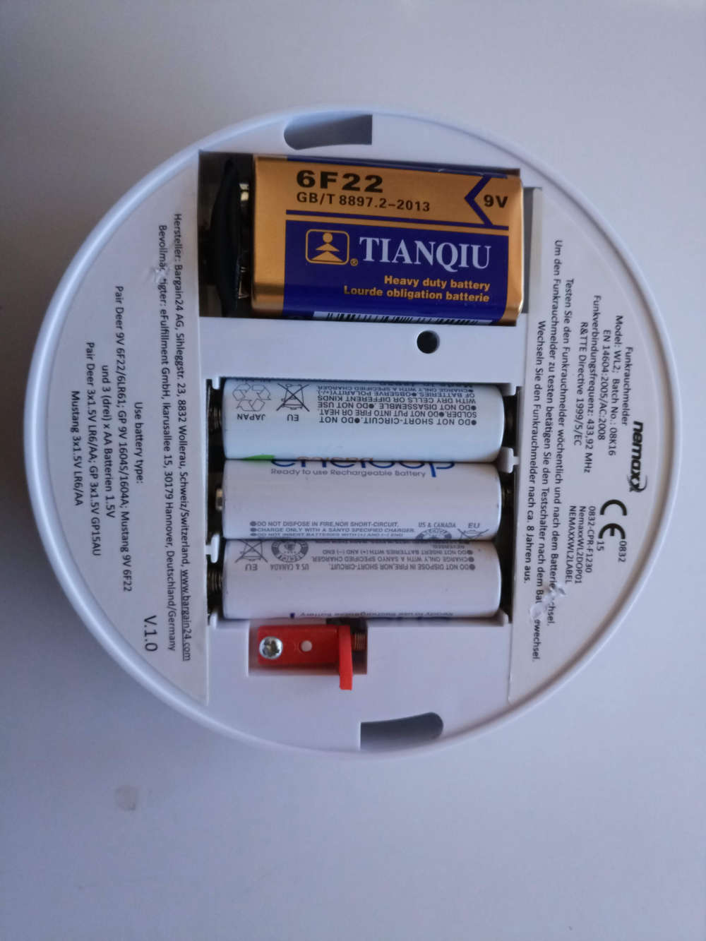
      I bought 5 of them for ~40 EUR a year ago from amazon.de . They use a 9V battery + 3x 1.5V AA batteries. They are able to network over 433Mhz; if 1 alarm is triggered, they will all sound alarm. Amazon link is below:
      https://www.amazon.de/Nemaxx-Funkrauchmelder-Rauchmelder-Brandmelder-koppelbar/dp/B00EZCMFPC/ref=sr_1_2?ie=UTF8&qid=1529688708&sr=8-2&keywords=nemaxx%2Bwl2&th=1

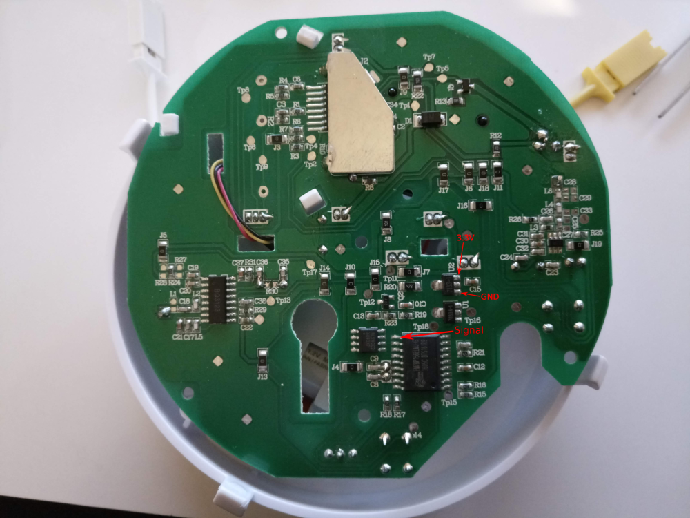
      I did a quick analysis of the PCB and here are the findings:

      • 9V battery powers the smoke detector and piezzo alarm part.
      • 3x 1.5V AA batteries powers a seperate MCU + flash memory through a 3.3V LDO regulator.
      • The MCU seems responsible for user interface (buttons and leds) and communications. It integrates with the smoke detector part.
      • MCU chip is em78p156el
      • When the alarm is activated, pin P64 is pulled low for the duration of the alarm.

      This makes it pretty easy to turn into a MySensors device. There is already a power source + LDO regulator with 3.3V output. Detecting the alarm activating / deactivating is very straightforward using the P64 pin.

      I'm only hesitating if I should use the LDO regulator outputs directly or rather add my own.

      1_1529692669044_pins.png
      0_1529692669044_IMG_20180622_191743.jpg

      posted in My Project
      freynder
      freynder
    • RE: STM32?

      @freynder said in STM32?:

      @freynder said in STM32?:

      stm32 sensor is unable to connect to gateway:

      After further testing, this seems to work now. I'm not exactly sure why unfortunately. I'm now using the new RFM69 library. I noticed that communication seems to fail after uploading the sketch over stlink, even when clicking the reset button. When disconnecting/reconnecting the usb power all works well. Maybe that was the issue previously as well.

      Just following up on this as I finally found out why this is happening. I was using encryption and using serial upload (using stm32flash), the simulated eeprom would get overwritten by the flash erase. Not sure if this happens for dfu or stlink as well. Uploading using the black magic probe (which uses dbg) does not have this problem. I hope this may help someone struggling with the same issue.

      Edit: not sure about dfu or stlink.

      posted in General Discussion
      freynder
      freynder
    • RE: Is the 32-bit ATSAML10 the ATMEGA328P killer that we've been waiting for?

      @nagelc That would be interesting. Remember also that MySensors currently only supports STM32F1 without sleep mode. I'm running a modified version with sleep support, but since I could not make it generic enough, I never submitted it as an enhancement (can be found here: github, 2.2.0 only)

      I still have a few prototype boards available but don't have enough time to progress much in the near future. If you would like a few boards (PCB only, not fully assembled) for experimenting and testing I can send you a few provided shipping costs permit it. I would love to see them better supported. Drop me a PM if interested.

      posted in Hardware
      freynder
      freynder
    • RE: Is the 32-bit ATSAML10 the ATMEGA328P killer that we've been waiting for?

      @neverdie said in Is the 32-bit ATSAML10 the ATMEGA328P killer that we've been waiting for?:

      You can even put a USB bootloader onto them.

      plus debug using Black Magic Probe or stlink + OpenOCD

      posted in Hardware
      freynder
      freynder
    • RE: Is the 32-bit ATSAML10 the ATMEGA328P killer that we've been waiting for?

      @yveaux and @scalz

      Thanks for confirming. So only Clark's core is supported at the moment.

      It would be interesting to support the official STM32 core as they provide low power functions. I will do some experiments.

      posted in Hardware
      freynder
      freynder