Navigation

    • Register
    • Login
    • OpenHardware.io
    • Categories
    • Recent
    • Tags
    • Popular
    1. Home
    2. hard-shovel
    3. Best
    • Profile
    • Following
    • Followers
    • Topics
    • Posts
    • Best
    • Groups

    Best posts made by hard-shovel

    • RE: Trouble wiring a Dalla 18B20 to Arduino D1 Mini

      @sirzlimz It may be stating the obvious but the photo shown is not a arduino processor but a ESP8266.
      Therefore the I/O pins listed in the sketch refer to the GPIO pin number on the ESP8266.
      So if PIN 2 is listed in the Sketch it refers to GPIO2 which is the pin marked D4 on the D1 mini module..

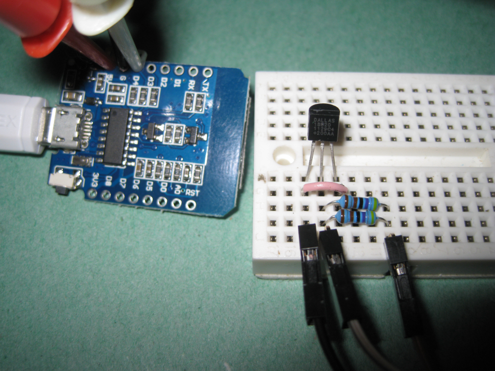
      The photo shows the Data jumper connected to D2, So trying moving this to D4 with the original sketch.

      posted in Hardware
      hard-shovel
      hard-shovel
    • RE: Trouble wiring a Dalla 18B20 to Arduino D1 Mini

      @sirzlimz I have just tried this circuit out myself on a D1 module and the using the library listed from milesburton it does not work on the ESP8266 in parasitic mode.
      If you move the jumper over for powered mode it will work fine.

      Trying on an Arduino nano with the same device and breadboard it works fine in both modes.

      So testing again and reading the data sheet on the DS18B20 and the section on "Powering the DS18B20" page 7 some insight can be obtained.

      Anyway a quick fix is to put another 4.7K resistor in parallel with the first and the system should work with one sensor,

      so two possible ways of connection are shown

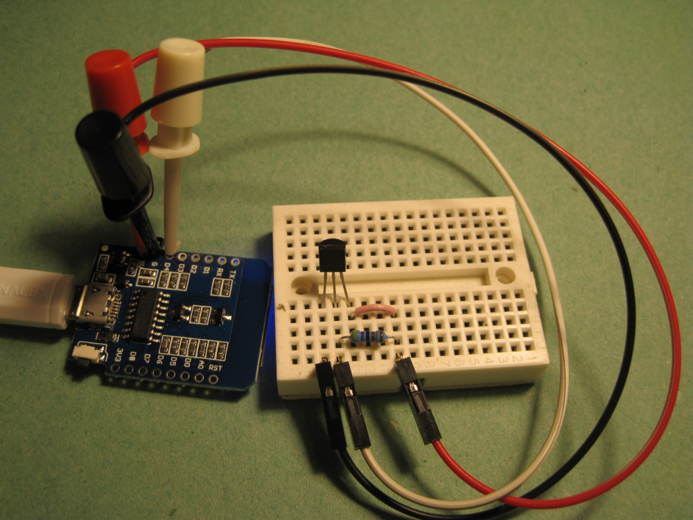
      Powered Mode with the Jumper to 5V, Recommended method, I always power my DS18B20's
      This works with multiple devices, (I have just tried with 10 devices on the D1 [with multiple device sketch])
      0_1520624348000_IMG_3652.JPG

      Parasitic Mode with two 4.7K resistors (this trick only works with one device on the bus)
      0_1520624437698_IMG_3653.JPG

      posted in Hardware
      hard-shovel
      hard-shovel
    • RE: Trouble wiring a Dalla 18B20 to Arduino D1 Mini

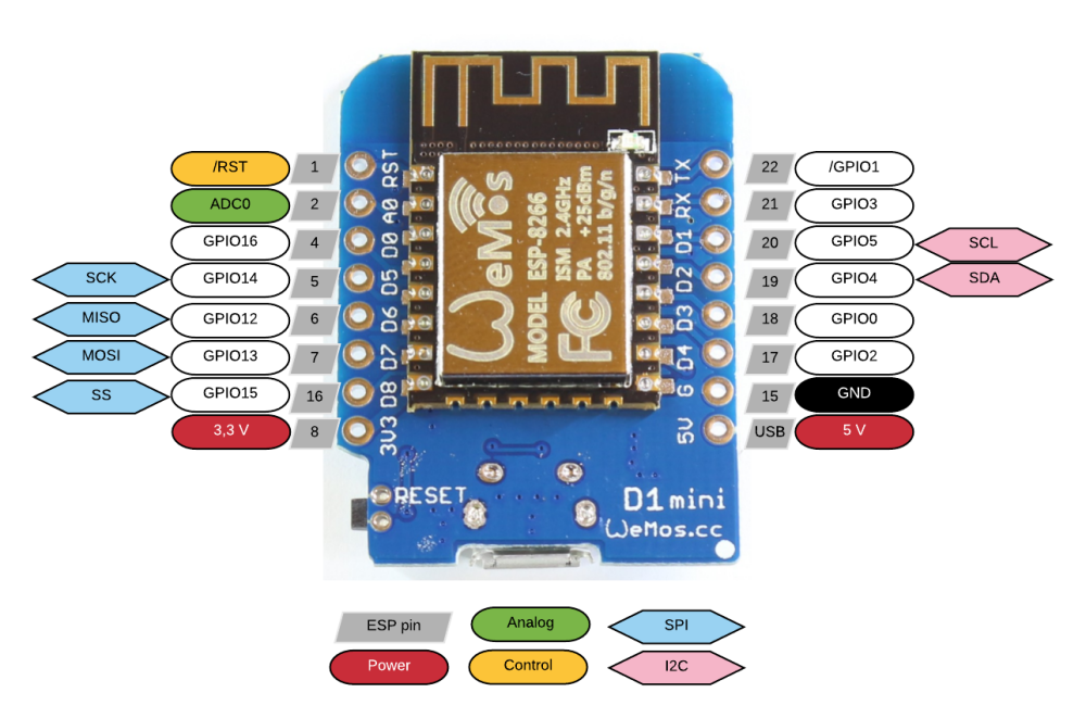
      @sirzlimz There are lots of pinout diagrams on the web like below.

      For the the arduino use the GPIO number as the pin number

      ie
      GPIO5 --- marked D1 in Arduino IDE use 5
      GPIO13-marked D7

      0_1520633752967_esp8266-wemos-d1-mini-pinout.png

      posted in Hardware
      hard-shovel
      hard-shovel
    • RE: Is it really required to remove the voltage regulator to save power?

      @benhub Short answers, No, Yes, Yes

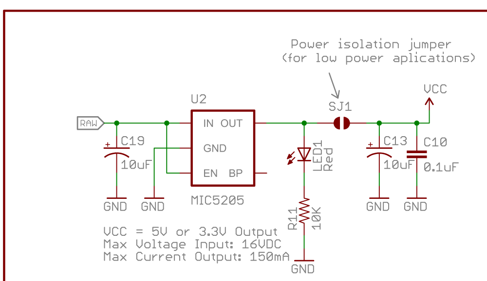
      The regulator will use power if connected.
      If your circuit is power hungry then removing the regulator will have limited effect.
      The sparkfun schematic on the article that you listed notes to disconnect the regulator for low power, so the advice is consistent.
      Unless you are using the genuine sparkfun versions of the pro-mini where the jumper can be cut then physically removing the regulator is recommended.
      0_1542936362010_Arduino-Pro-Mini-v14 regulator part.png

      posted in Hardware
      hard-shovel
      hard-shovel
    • RE: 💬 PogoPins

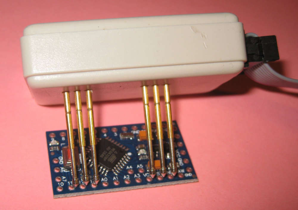
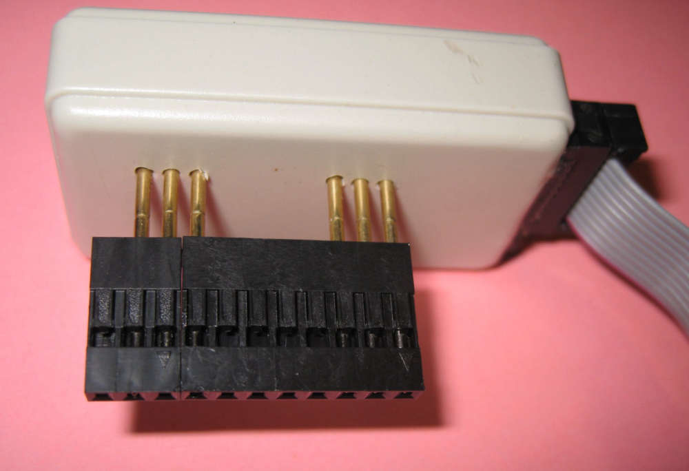
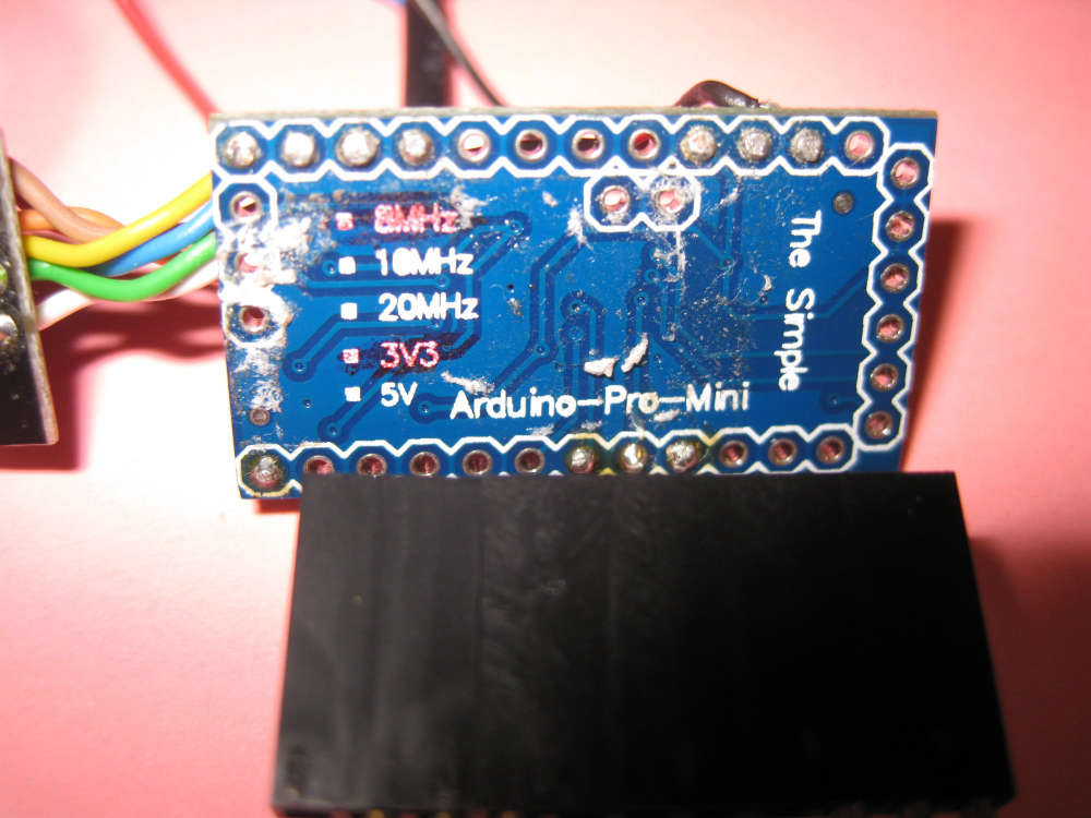
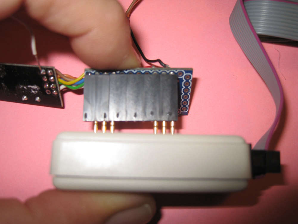
      I made a simple adapter for Pro Minis, Used on it own for new boards with connection holes
      0_1539605590332_Img_4455y.jpg

      If you slide on some dupont cable covers as a guide it makes it easy to program a soldered board
      0_1539605765924_Img_4456y.jpg

      0_1539605916766_Img_4462y.jpg

      0_1539606003550_Img_4457y.jpg

      posted in OpenHardware.io
      hard-shovel
      hard-shovel
    • RE: Water Sensor

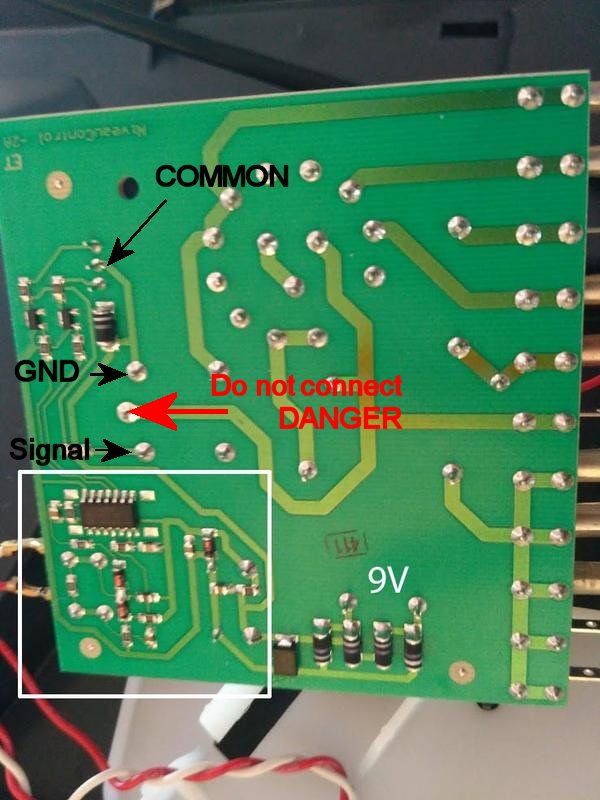
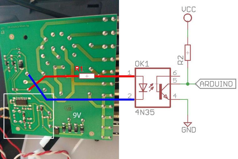
      The Led is not actualy runing on AC. Part of the IC generates an low voltage AC signal (Nothing to do Mains Power) then other parts of the IC detect changes to this signal via the pair of diodes at the bottom, and then generate the two signals for the red and green leds.

      The bicolor color led has a common terminal in the center and the two outer pins control the two outer pins power the red and green leds.

      Utilizing a optocoupler has a safety advantage, as it isolates the power on the sensed unit from the mysensor node. It also allows systems using different control signal voltages to be interconnected.

      If you have the arduino analogue pin connected to Pin3, where do you have the arduino GND connected?

      As there is a relay that is connected in parallel to the the Upper LED drive transistor,
      I recommend using a optocoupler and resistor connected to the relay terminals shown, as these connections are easy to solder wires to.
      The resistor will need to be sized to match the voltage on the relay to limit current through the optocoupler led. 0_1516034196873_Electrolux Control Board 213.jpg

      posted in Hardware
      hard-shovel
      hard-shovel
    • RE: Water Sensor

      The TLP222A are opto-Mosfet devices so ideal for powering LEDs and small Relays etc as they have a 500mA rating, and the price listed is good value.

      However for your application, use the 4N35 that you already have.
      Your diagram is reversed as you need to drive the led in the optocoupler from the relay coil connections.

      Use the existing 10K as a pullup resistor at the input to the arduino,
      On the relay side use a series resistor R1 of about 1Kohm for 12Vdc (expected from a 9Vac supply).0_1516275929555_Water Sensor 213-B.jpg

      posted in Hardware
      hard-shovel
      hard-shovel
    • RE: With MySensors PC cold start!

      The pins on the sketch and the schematic do not match,
      You need to be more careful on matching the items as it will make troubleshooting more difficult.

      This sketch is a quick and dirty method, that does basically to work for me using OpenHAB as a controller. (only tested using LED outputs not with an actual computer).
      If i was actually going to implement this, I would monitor the POWER LED on the computer for feedback and control of the pulses. ie for shutdown, try short pulse first for controlled shutdown and if not shutdown within expected time span, then preform a hard shutdown.

      /*
       * PC Power On/Off & Reset Sketch
       *  Power Pin Pulse         = PC Starts if Already Off,     *** PC Shutsdown if already on   ## this is the operation of my Computer ##
       *  Power Pin 5 Seconds Low = PC Forced Shutdown
       *  Reset Pin Pulse Low     = PC Reset (if already on)
       *  
       *  Using three child IDs 
       *  1 = Power On/Off
       *  2 = Forced OFF
       *  3 = Reset
       *  
       *  Version 1.0 2018-01-19
       */
      
      /**
       * The MySensors Arduino library handles the wireless radio link and protocol
       * between your home built sensors/actuators and HA controller of choice.
       * The sensors forms a self healing radio network with optional repeaters. Each
       * repeater and gateway builds a routing tables in EEPROM which keeps track of the
       * network topology allowing messages to be routed to nodes.
       *
       * Created by Henrik Ekblad <henrik.ekblad@mysensors.org>
       * Copyright (C) 2013-2015 Sensnology AB
       * Full contributor list: https://github.com/mysensors/Arduino/graphs/contributors
       *
       * Documentation: http://www.mysensors.org
       * Support Forum: http://forum.mysensors.org
       *
       * This program is free software; you can redistribute it and/or
       * modify it under the terms of the GNU General Public License
       * version 2 as published by the Free Software Foundation.
       *
       *******************************
       *
       * REVISION HISTORY
       * Version 1.0 - Henrik Ekblad
       *
       * DESCRIPTION
       * Example sketch showing how to control physical relays.
       * This example will remember relay state after power failure.
       * http://www.mysensors.org/build/relay
       */
      
      
      // Enable debug prints to serial monitor
      #define MY_DEBUG
      
      //#define MY_NODE_ID AUTO
      #define MY_NODE_ID 155            // my test Node ID,  Comment out for Auto ID
      
      // Enable and select radio type attached
      #define MY_RADIO_NRF24
      //#define MY_RADIO_NRF5_ESB
      //#define MY_RADIO_RFM69
      //#define MY_RADIO_RFM95
      
      // Enable repeater functionality for this node
      #define MY_REPEATER_FEATURE   // if you need the repeater function uncomment
      
      #include <MySensors.h>
      
      // Wait times
      #define LONG_WAIT 500
      #define SHORT_WAIT 50
      #define PULSE_TIME 500UL      // half a second
      #define FORCED_TIME 5000UL    // 5 seconds
      boolean goPulse;
      unsigned long pulseStartTime;
      
      #define POWER_PIN   4         // Arduino Digital I/O pin number for PC Power control
      #define RESET_PIN   5         // Arduino Digital I/O pin number for PC Reset control
      
      #define RELAY_ON    1         // GPIO value to write to turn on attached relay
      #define RELAY_OFF   0         // GPIO value to write to turn off attached relay
      #define CHILD_ID_POWER       143        // these ID used for my test machine.   change to suit ie 1
      #define CHILD_ID_FORCEDOFF   144        // change to suit ie 2
      #define CHILD_ID_RESET       145        // change to suit ie 3
      boolean Status_Power      =  0;
      boolean Status_Forcedoff  =  0;
      boolean Status_Reset      =  0;
      boolean is_Power          =  0;
      boolean is_ForcedOff      =  0;
      boolean is_Reset          =  0;
      
      // Setup Messages
      MyMessage msg(CHILD_ID_POWER,V_STATUS);
      
      void before() {
        //  Set the pins to output mode
          pinMode(POWER_PIN, OUTPUT);
          pinMode(RESET_PIN, OUTPUT);
        //  Set the Pin states to known state
          digitalWrite(POWER_PIN, RELAY_OFF);
          digitalWrite(RESET_PIN, RELAY_OFF);
      }
      
      void setup() {
      
      }
      
      void presentation() {
          // Send the sketch version information to the gateway and Controller
          sendSketchInfo("Relay", "1.0");
          wait(LONG_WAIT);        // Give gateway time to Process
      // Present child ids to conroller
          present(CHILD_ID_POWER, S_BINARY, "PC Power on-off");
          wait(SHORT_WAIT);        // Give gateway time to Process
          present(CHILD_ID_FORCEDOFF, S_BINARY, "PC Forced off");
          wait(SHORT_WAIT);        // Give gateway time to Process
          present(CHILD_ID_RESET, S_BINARY, "PC Reset");
          wait(SHORT_WAIT);        // Give gateway time to Process  
      }
      
      
      void loop() {
      Serial.println();  
      Serial.print ("loop start ");
      
      
      send(msg.setSensor(CHILD_ID_POWER).set( Status_Power));
      send(msg.setSensor(CHILD_ID_FORCEDOFF).set( Status_Forcedoff));
      send(msg.setSensor(CHILD_ID_RESET).set( Status_Reset));
      wait(100000);        // wait for testing 
      }
      
      void receive(const MyMessage &message)
      {
          // We only expect one type of message from controller. But we better check anyway.
          if (message.type==V_STATUS) 
          switch (message.sensor) {
          case CHILD_ID_POWER:
            is_Power = message.getBool();
            Serial.print("incoming change for Power:");
            Serial.print(message.sensor);
            Serial.print(", New status: ");
            Serial.println((is_Power ? "On":"Off"));
            powercmd();        // process pulses etc in subroutine
            break;
          case CHILD_ID_FORCEDOFF:
            is_ForcedOff = message.getBool();
            Serial.print("incoming change for FORCED Power OFF:");
            Serial.print(message.sensor);
            Serial.print(", New status: ");
            Serial.println((is_ForcedOff ? "On":"Off"));
            forcedcmd();
            break;   
          case CHILD_ID_RESET :
            is_Reset = message.getBool();
            Serial.print("incoming change for Reset:");
            Serial.print(message.sensor);
            Serial.print(", New status: ");
            Serial.println((is_Reset ? "On":"Off"));
            resetcmd();
            break;
      
          default:
            Serial.print("Unknown/UnImplemented message type: ");
            Serial.println(message.type);
        }
      
      }


      void powercmd() {
        // process power pin 
        if (is_Power != Status_Power) {
          digitalWrite(POWER_PIN, RELAY_ON);
          delay(PULSE_TIME);          // delay used as pulse time is short & multiple processes are not expected
          digitalWrite(POWER_PIN, RELAY_OFF);
          Status_Power = is_Power;
        }
      }
      
      void forcedcmd() {
        // process forced power off command
          if (is_ForcedOff = 1 ) {
          digitalWrite(POWER_PIN, RELAY_ON);
          delay(FORCED_TIME);          // delay used as multiple processes are not expected, quick and dirty
          digitalWrite(POWER_PIN, RELAY_OFF);
          Status_Forcedoff = 0;          // reset status for next time
          Status_Power =  0;          // power status also reset if power shutoff
          }
      }
      
      void resetcmd() {
        // process reset command
        if (is_Reset != 1 ) {
          digitalWrite(RESET_PIN, RELAY_ON);
          delay(PULSE_TIME);          // delay used as multiple processes are not expected, quick and dirty
          digitalWrite(RESET_PIN, RELAY_OFF);
          Status_Reset = 0;
        }
      }
      
      
      posted in My Project
      hard-shovel
      hard-shovel
    • RE: Only a hard reset works.

      @robert the NUMBER_OF_RELAYS is already defined in your sketch, just use as pasted.

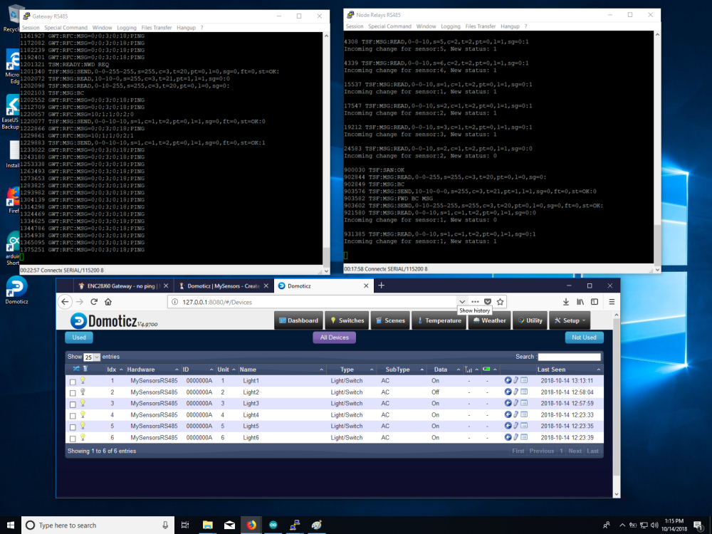
      I use OpenHAB so i just tried to install Dormotiz and was supreised that it took less than a an hour to install and get working with the relays. (Most of that time was trying to get them to shown up on the dashboard)

      Dormotiz is communication fine with my node and i can switch on and off the relays from the Dashboard

      0_1539548686702_Domoricz RS485 3.png

      In the sort time i have checked i do see that the Last Seen time only changes when i change the state of the relay.

      So your program that you posted works for me with both my normal OpenHAB and the new test Domoticz.

      I think that i may be miss understanding your actual problem.

      posted in General Discussion
      hard-shovel
      hard-shovel
    • RE: Combining DS18B20 and relay..

      @mela You are presenting the devices as Relay Child 1, and Temperature sensors as Child Ids 5 and 6.

      But when sending you are sending the temperatures as Child Ids 0 and 1

      Change the following send line

            // Send in the new temperature
            send(msg.setSensor(i).set(temperature,1));
      

      to

            // Send in the new temperature
            send(msg.setSensor(i+5).set(temperature,1));
      

      so the send function matches the presentation values.

      posted in Troubleshooting
      hard-shovel
      hard-shovel
    • RE: Water Sensor

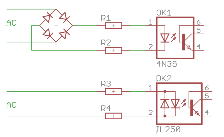
      To sense the 220V without a bridge rectifer use an ac version of the opto-isolator, The optocoupler will still need the rest of the components ie resistors and/or capacitors.
      typical types are H11AA1 or LTV814 etc

      0_1516572230867_Opto-Couplers.png

      link text

      posted in Hardware
      hard-shovel
      hard-shovel
    • RE: Sensors error

      @ek-wik you are describing sensor repeatability,

      posted in General Discussion
      hard-shovel
      hard-shovel
    • RE: Multiple Dallas Temperatuur sensors at one sensor node

      @dzjr you have the define

      #define TEMPERATURE_PRECISION 12
      

      In the github code this is not utilized, so the sensors are operating in 9 bit resolution.

      You need to add the following in the before or setup

      sensors.setResolution(TEMPERATURE_PRECISION);
      
      posted in Troubleshooting
      hard-shovel
      hard-shovel
    • RE: ENC28J60 Gateway - no ping

      @daniele-frigo
      I have just tried your code with the separate module type ENC28J60 and get the following Debug output, and pinging is successful.

      0 MCO:BGN:INIT GW,CP=R-NGA---,VER=2.3.1-alpha
      54 GWT:TIN:IP=192.168.1.22
      1056 MCO:BGN:STP
      1058 MCO:REG:NOT NEEDED
      1060 MCO:BGN:INIT OK,TSP=NA
      

      I only have the following connected
      +5V, GND, SO-12, SCK-13, SI-11, CS-10 (INT-2, RESET-RESET)

      Have you tried unplugging the nano from the ENC28J60 Shield and just using the above jumpers?

      My module also has CLK and WOL that are unconnected, Could it be that your module has these connected somehow?

      posted in Hardware
      hard-shovel
      hard-shovel
    • RE: How to read frequency and SWP output from watermark sensor

      Hi
      Well i think that 48Hz is good for a very dry sensor or disconnected unit.
      If you do not wish to get the sensor wet, you could try connecting various resistors to the input to simulate the sensor and vary the frequency signal.

      I tested the following program using a signal generator to input the frequency signal to test the conversions as the SMX datasheet,

      There are the three main functions:
      Input Pin to Frequency
      Frequency to Resistance (using a lookup table as per page 6)
      Resistance to kPa (using a lookup table as per page 7 with Fahrenheit temperature compensation)
      Alternative Resistance to kPA (using the calculation on page 9 with Celsius temperature compensation)

      I have not included any temperature conversions from Fahrenheit to Celsius so each function uses the temperature as per the data sheet.

      My code is just quick and simple just to get started.

      // test program to test Watermark Sensor using the SMX interface using frequency mode.
      // see https://forum.mysensors.org/topic/9384/how-to-read-frequency-output-from-watermark-sensor
      // see http://emesystems.com/pdfs/SMX.pdf for data sheet
      
      
      // global var
      int signal_input_pin = 4;  // Sensor pulse pin
      float TsoilF = 75;         // Soil temperature in  Fahrenheit
      float TsoilC = 24;         // Soil temperature in  Centrigrade
      
      long RESISTORarray[76] = {
      // Watermark Sensor SMX interface Hz to Resistance lookup table per SMX.pdf page 6. 
      48,  10000000,
      76,  262144,
      85,  196608,
      103, 131072,
      122, 98304,
      157, 65536,
      194, 49152,
      264, 32768,
      335, 24567,
      476, 16384,
      612, 12288,
      874, 8192,
      1135,  6144,
      1623,  4096,
      2071,  3072,
      2862,  2048,
      3557,  1536,
      4697,  1024,
      5596,  768,
      6932,  512,
      7878,  384,
      9104,  256,
      9882,  192,
      10802, 128,
      11312, 96,
      11893, 64,
      12200, 48,
      12526, 32,
      12708, 24,
      12871, 16,
      12962, 12,
      13047, 8,
      13092, 6,
      13139, 4,
      13162, 3,
      13186, 2,
      13209, 1,
      13233, 0,
      };
      
      long SWPkPAarray[18]{
      // Watermark Sensor SMX interface Resistance to SWP kPa lookup table per SMX.pdf page 7. 
      // this table is valid at temperature of 75F, 24C  
       550,  0,
      1000,  9,
      1100,  10,
      2000,  15,
      6000,  35,
      9200,  55,
      12200, 75,
      15575, 100,
      28075, 200,
      };
      
      
      void setup() {
          // initialize the serial communications:
        Serial.begin(115200);
        Serial.println("Watermark Fequency Display");
        pinMode (INPUT, signal_input_pin);
      }
      
      
      void loop() {
        // put your main code here, to run repeatedly:
        float Signal_Freqency = freqencyMeasure(signal_input_pin);
        Serial.print(" Frequency H+L; = ");
        Serial.print(Signal_Freqency);
        Serial.print("   ");
        
        float Signal_Resistance = resistanceCalc(Signal_Freqency);
        Serial.print(" Resistance; = ");
        Serial.print(Signal_Resistance);
        Serial.print("   ");
        
        float Signal_kPa = kPaCalc(Signal_Resistance, TsoilF);     // input using Fahrenheit temperature
        Serial.print(" kPA ; = ");
        Serial.print(Signal_kPa);
        Serial.print("   ");
        
        float Signal_kPa2 = kPaCalc2(Signal_Resistance, TsoilC);   // input using Celcius temperature
        Serial.print(" kPA Version 2; = ");
        Serial.print(Signal_kPa2);
        Serial.print("   ");
          
        //float Signal_Freqency2 = freqencyMeasure2(signal_input_pin);
        //Serial.print(" Frequency H*2; = ");
        //Serial.println(Signal_Freqency2);
        //Serial.print("   ");
      
       
        Serial.print(" Perentage; = ");
        Serial.println(map(Signal_kPa, 0,200,0,100));
        Serial.print("   ");
        
        delay(500);
      }
      
      //---------------------------------------------------------------
      long resistanceCalc(float frequencyInput){
        // Convert from freqency to Resistance measurement
        // From SMX.pdf datasheet, page 6
        // 48 Hz    = 10,000,000 Ohms
        // 76 Hz    =    262,144 Ohms
        // 13233 Hz =          0 ohms 
        // using lookup table held in the array  RESISTORarray   
      
        //frequencyInput = constrain(frequencyInput,50, 13233);
        float newVal;
        if (frequencyInput <= RESISTORarray[0]) {     // Minimum value
          newVal = RESISTORarray[0+1];
        }
        if (frequencyInput >= RESISTORarray[74]) {     // Maximum value
          newVal = RESISTORarray[74+1];
        }  
        for (int i=0; i<74; i=i+2) {
          if ((frequencyInput >= RESISTORarray[i]) && (frequencyInput <= RESISTORarray[i+2])) {
            newVal = RESISTORarray[i+1] - ((RESISTORarray[i+1]-RESISTORarray[i+3]) * ((frequencyInput-RESISTORarray[i]) / (RESISTORarray[i+2]-RESISTORarray[i])));
            break;
          }
        }
        return newVal;
      }
      
      //---------------------------------------------------------------
      long kPaCalc(float ResistanceInput, float FTemperatureInput){
        // Convert from Resistance to SWP kPa measurement
        // From SMX.pdf datasheet, page 7
        //   550 Ohms =  0 SWP kPa
        //  6000 Ohms = 35 SWP kPa
        // 28075 Ohms =200 SWP kPa
        // using lookup table held in the array  SWPkPAarray   
        // table valid for temperature of 75F, 24C
        // for increase of 1°F increase resistance by 1%.
        // ** this function accepts temperature in Fahrenheit units **
        float newVal;
      
        // Adjust compensate resistance for temperature.
        // per page 8 of SMX.pdf 
        float ResistanceCompensated = ResistanceInput;
        
          if (ResistanceCompensated <= SWPkPAarray[0]) {     // Minimum value
          newVal = SWPkPAarray[0+1];
        }
        if (ResistanceCompensated >= SWPkPAarray[74]) {     // Maximum value
          newVal = SWPkPAarray[16+1];
        }  
        //for (int i=0; i<SWPkPAarray.length-2; i=i+2) {
        for (int i=0; i<16; i=i+2) {
          if ((ResistanceCompensated >= SWPkPAarray[i]) && (ResistanceCompensated <= SWPkPAarray[i+2])) {
            newVal = SWPkPAarray[i+1] - ((SWPkPAarray[i+1]-SWPkPAarray[i+3]) * ((ResistanceInput-SWPkPAarray[i]) / (SWPkPAarray[i+2]-SWPkPAarray[i])));
            break;
          }
        }
        return newVal;
      }
      
      
      //---------------------------------------------------------------
      long kPaCalc2(float ResistanceInput, float CTemperatureInput){
        // Second Method of conversion
        // Convert from Resistance to SWP kPa measurement
        // From SMX.pdf datasheet, page 9
        // kPa = (3.213 * kohms + 4.093) / {1 - 0.009733 * kohms - 0.01205 * Celsius)
        // ** this function accepts temperature in Celsius units **
        
        ResistanceInput = ResistanceInput/1000;     // ohms to Kohms
        float newVal = (3.213 * ResistanceInput + 4.093) / (1 - 0.009733 * ResistanceInput - 0.01205 * CTemperatureInput);
        return newVal;
      }
      
      
      //---------------------------------------------------------------
      long freqencyMeasure(int input_pin) {
        // if mark-space ratio is equal then only one measurement High time or low time and double it is required.
        int HighInput;      // Store high time of wave in microseconds
        int LowInput;       // store Low time of wave in microseconds
        float TotalInput;   // Temp store of total time of duration for one cycle of high and low pulse
        float frequency;    // calculated freqency   1/total time of one cycle.
        HighInput = pulseIn(input_pin,HIGH);
        LowInput  = pulseIn(input_pin,LOW);
        TotalInput = HighInput + LowInput;
        frequency = 1000000L / TotalInput;
        /*
        Serial.print(" HighInput; = ");
        Serial.print(HighInput);
        Serial.print("   ");
        Serial.print(" Low Input; = ");
        Serial.print(LowInput);
        Serial.print("   ");
        */
        if (HighInput >0 && LowInput>0) return frequency;   // reading valid
        return 0;
       } 
      
      //---------------------------------------------------------------
       long freqencyMeasure2(int input_pin) {
        // if mark-space ratio is equal then only one measurement High time or low time and double it is required.
        int HighInput;      // Store high time of wave in microseconds
        int LowInput;       // store Low time of wave in microseconds
        float TotalInput;   // Temp store of total time of duration for one cycle of high and low pulse
        float frequency;    // calculated freqency   1/total time of one cycle.
        HighInput = pulseIn(input_pin,HIGH);
        //LowInput  = pulseIn(input_pin,LOW);
        TotalInput = HighInput *2;
        frequency = 1000000L / TotalInput;
        if (HighInput >0) return frequency;   // reading valid
        return 0;
       } 
      

      I hope this helps.

      posted in Development
      hard-shovel
      hard-shovel
    • RE: ESP8266Wifi Gateway won't connect

      @OldSurferDude have you set the MQTT user and MQTT passwords in the sketch and uncommented them as well?

      // Enable these if your MQTT broker requires usenrame/password
      //#define MY_MQTT_USER "username"
      //#define MY_MQTT_PASSWORD "password"
      
      // Enable these if your MQTT broker requires usenrame/password
      #define MY_MQTT_USER "MQTTusername2022"
      #define MY_MQTT_PASSWORD "MQTTpassword2022"
      

      what does your debug log look like?
      This sample is not connected correctly to the MQTT Broker

      10:33:26.151 -> dhcp client start...
      10:33:26.151 -> 341 TSM:INIT:GW MODE
      10:33:26.199 -> 364 TSM:READY:ID=0,PAR=0,DIS=0
      10:33:26.199 -> 396 MCO:REG:NOT NEEDED
      10:33:26.339 -> 505 GWT:TPC:CONNECTING...
      10:33:27.365 -> 1533 MCO:BGN:STP
      10:33:27.365 -> 1551 MCO:BGN:INIT OK,TSP=1
      10:33:27.412 -> 1579 TSM:READY:NWD REQ
      10:33:27.412 -> 1606 ?TSF:MSG:SEND,0-0-255-255,s=255,c=3,t=20,pt=0,l=0,sg=0,ft=0,st=OK:
      10:33:28.671 -> scandone
      10:33:35.993 -> pm open,type:2 0
      10:33:44.664 -> 18861 TSF:MSG:READ,254-254-255,s=255,c=3,t=7,pt=0,l=0,sg=0:
      10:33:44.758 -> 18924 TSF:MSG:BC
      10:33:44.758 -> 18942 TSF:MSG:FPAR REQ,ID=254
      10:33:44.804 -> 18973 TSF:PNG:SEND,TO=0
      10:33:44.804 -> 18998 TSF:CKU:OK
      10:33:44.851 -> 19016 TSF:MSG:GWL OK
      10:33:45.459 -> 19646 TSF:MSG:SEND,0-0-254-254,s=255,c=3,t=8,pt=1,l=1,sg=0,ft=0,st=OK:0
      10:33:46.671 -> 20876 TSF:MSG:READ,254-254-0,s=255,c=3,t=24,pt=1,l=1,sg=0:1
      10:33:46.766 -> 20939 TSF:MSG:PINGED,ID=254,HP=1
      10:33:46.813 -> 20980 TSF:MSG:SEND,0-0-254-254,s=255,c=3,t=25,pt=1,l=1,sg=0,ft=0,st=OK:1
      10:33:46.860 -> 21057 TSF:MSG:READ,254-254-0,s=255,c=3,t=15,pt=6,l=2,sg=0:0100
      

      This is working correctly

      10:36:34.908 -> dhcp client start...
      10:36:37.655 -> ip:192.168.1.202,mask:255.255.255.0,gw:192.168.1.254
      10:36:37.702 -> 7014 GWT:TPC:IP=192.168.1.202
      10:36:37.702 -> 7100 GWT:RMQ:CONNECTING...
      10:36:37.749 -> 7144 GWT:RMQ:OK
      10:36:37.795 -> 7161 GWT:TPS:TOPIC=mygateway4-out/0/255/0/0/18,MSG SENT
      10:36:44.792 -> pm open,type:2 0
      10:38:56.629 -> 146027 TSF:MSG:READ,254-254-255,s=255,c=3,t=7,pt=0,l=0,sg=0:
      10:38:56.723 -> 146091 TSF:MSG:BC
      10:38:56.723 -> 146109 TSF:MSG:FPAR REQ,ID=254
      10:38:56.770 -> 146142 TSF:PNG:SEND,TO=0
      10:38:56.770 -> 146168 TSF:CKU:OK
      10:38:56.816 -> 146187 TSF:MSG:GWL OK
      10:38:57.655 -> 147013 TSF:MSG:SEND,0-0-254-254,s=255,c=3,t=8,pt=1,l=1,sg=0,ft=0,st=OK:0
      10:38:58.683 -> 148042 TSF:MSG:READ,254-254-0,s=255,c=3,t=24,pt=1,l=1,sg=0:1
      10:38:58.730 -> 148105 TSF:MSG:PINGED,ID=254,HP=1
      10:38:58.776 -> 148148 TSF:MSG:SEND,0-0-254-254,s=255,c=3,t=25,pt=1,l=1,sg=0,ft=0,st=OK:1
      10:38:58.869 -> 148226 TSF:MSG:READ,254-254-0,s=255,c=3,t=15,pt=6,l=2,sg=0:0100
      10:38:58.916 -> 148294 TSF:MSG:SEND,0-0-254-254,s=255,c=3,t=15,pt=6,l=2,sg=0,ft=0,st=OK:0100
      10:38:59.010 -> 148375 TSF:MSG:READ,254-254-0,s=255,c=0,t=17,pt=0,l=11,sg=0:2.4.0-alpha
      10:38:59.058 -> 148450 GWT:TPS:TOPIC=mygateway4-out/254/255/0/0/17,MSG SENT
      10:38:59.151 -> 148515 TSF:MSG:READ,254-254-0,s=255,c=3,t=6,pt=1,l=1,sg=0:0
      10:38:59.197 -> 148578 GWT:TPS:TOPIC=mygateway4-out/254/255/3/0/6,MSG SENT
      10:39:00.923 -> 150319 TSF:MSG:READ,254-254-0,s=255,c=3,t=11,pt=0,l=14,sg=0:MockMySensors 
      10:39:01.017 -> 150398 GWT:TPS:TOPIC=mygateway4-out/254/255/3/0/11,MSG SENT
      10:39:01.064 -> 150462 TSF:MSG:READ,254-254-0,s=255,c=3,t=12,pt=0,l=4,sg=0:v0.5
      10:39:01.157 -> 150529 GWT:TPS:TOPIC=mygateway4-out/254/255/3/0/12,MSG SENT
      10:39:01.949 -> 151337 TSF:MSG:READ,254-254-0,s=1,c=0,t=0,pt=0,l=12,sg=0:Outside Door
      10:39:02.044 -> 151410 GWT:TPS:TOPIC=mygateway4-out/254/1/0/0/0,MSG SENT
      10:39:02.091 -> 151471 TSF:MSG:READ,254-254-0,s=255,c=3,t=26,pt=1,l=1,sg=0:2
      10:39:02.184 -> 151542 TSF:MSG:SEND,0-0-254-254,s=255,c=3,t=27,pt=1,l=1,sg=0,ft=0,st=OK:1
      10:39:02.699 -> 152055 TSF:MSG:READ,254-254-0,s=255,c=3,t=0,pt=1,l=1,sg=0:83
      
      posted in Troubleshooting
      hard-shovel
      hard-shovel
    • RE: ENC28J60 Gateway - no ping

      @daniele-frigo I have just tried my setup again using Mysensor 2.3.0 and I still get the same debug and ping response.

      I also get the same five lines of debug output even if the ENC28J60 is not connected. So i wonder why your output is only one line with the same code above!

      If I power my ENC28J60 with only +5V and GND and no other connections
      I get the Power LED on and then with a network cable connected the Green Link LED solid ON at the network connector and random blinking of the Yellow traffic LED

      So you could have a problem with the Power or Regulator on your board.

      posted in Hardware
      hard-shovel
      hard-shovel
    • RE: Problem with dimmable LED actuator with encoder

      @vladimir
      To deal with the encoder giving two pulses per indent change the following two lines in checkRotaryEncoder:

      //-------------------------------------------------------
      void checkRotaryEncoder() {
        long encoderValue = knob.read()>>1 ;      //### Divide by 2 (using shift right) 
      
        if (encoderValue > 100) {   
          encoderValue = 100;       
          knob.write(200);                        //### max value now 200 due to divide by 2
        } else if (encoderValue < 0) {
          encoderValue = 0;
          knob.write(0);
        }
      
        if (encoderValue != fadeTo) {    
          fadeTo = encoderValue;                   
          changedByKnob = true;
          startFade();
        }
      }
      

      and the receive function change one line

       if (!changedByKnob) 
          knob.write(fadeTo<<1);             //### need to multiply by two (using Shift left)
      

      If you use a different encoder you may have to change back these settings to the original

      For the switch Pushbutton problem change the two lines in the receive function section

        if (message.type == V_STATUS) {  //## change from V_LIGHT
      
      
         } else if (message.type == V_PERCENTAGE) {    //## change from V_DIMMER
      
      posted in Development
      hard-shovel
      hard-shovel
    • RE: ESP8266Wifi Gateway won't connect

      @OldSurferDude You are getting regular GWT:TSA:ETH OK message which i do not and you have no
      MSG SENT lines

      Which MQTT broker are you using?

      my test setup which i hope matches yours is:
      MySensors 2.3.2 & ESP8266 core 2.7.4
      ESP8266 Node MCU with sketch GatewayESP8266MQTTClient
      MY_BAUD_RATE 9600
      MY_MQTT_USER & MQTT_PASSWORD commented out
      MY_CONTROLLER_IP_ADDRESS 192, 168, 1, 195 address of the MQTT broker
      MY_CONTROLLER_URL_ADDRESS "MQTT-TEST-W10" commented out Use IP or URL not Both
      MY_PORT 1883

      MQTT Broker
      Mosquitto 2.0.15 running as a service on a windows 10 machine
      listener 1883 anonymous access
      URL MQTT-TEST-W10

      When connected to the MQTT Broker and receiving messages from a node the gateway shows

      09:48:18.962 -> 718935 TSF:MSG:READ,254-254-0,s=1,c=1,t=16,pt=2,l=2,sg=0:0
      09:48:19.010 -> 718997 GWT:TPS:TOPIC=mygateway5-out/254/1/1/0/16,MSG SENT
      
      09:48:19.104 -> 719059 TSF:MSG:READ,254-254-0,s=1,c=1,t=15,pt=1,l=1,sg=0:1
      09:48:19.149 -> 719121 GWT:TPS:TOPIC=mygateway5-out/254/1/1/0/15,MSG SENT
      
      09:48:19.198 -> 719182 TSF:MSG:READ,254-254-0,s=255,c=3,t=0,pt=1,l=1,sg=0:83
      09:48:19.292 -> 719246 GWT:TPS:TOPIC=mygateway5-out/254/255/3/0/0,MSG SENT
      

      if a message is sent to the broker the gateway shows

      10:03:54.285 -> 1654209 GWT:IMQ:TOPIC=mygateway5-in/254/255/1/0/15, MSG RECEIVED
      10:03:54.331 -> 1654279 TSF:MSG:SEND,0-0-254-254,s=255,c=1,t=15,pt=0,l=1,sg=0,ft=0,st=OK:1
      10:03:54.423 -> 1654358 TSF:MSG:READ,254-254-0,s=1,c=1,t=16,pt=2,l=2,sg=0:1
      10:03:54.471 -> 1654421 GWT:TPS:TOPIC=mygateway5-out/254/1/1/0/16,MSG SENT
      10:03:54.565 -> 1654483 TSF:MSG:READ,254-254-0,s=1,c=1,t=15,pt=1,l=1,sg=0:1
      10:03:54.611 -> 1654546 GWT:TPS:TOPIC=mygateway5-out/254/1/1/0/15,MSG SENT
      
      posted in Troubleshooting
      hard-shovel
      hard-shovel
    • RE: 💬 Dimmable LED Actuator

      @mateos78
      Attached is a sketch that i have just tried with domoticz (running on a windows test machine) It works fine when used as a node with a gateway. Encoder/ Switch and webpage slider/switch operating.

      However when set up as a single gateway node as your sketch, only the encoder function works, you can vary the lamp level from the slider or the encoder, but the domaticz on/off or the button does not operate correctly. it seems to be the way the messages are acknowledged

      I also find that when i change the led dimmer from the encoder the led changes quickly, but it take about ten seconds before the dormoticz web page updates to show each new slider position.

      The following Sketch needs the #define OPENHAB2 defined for use with openhab and undefined for Dormoticz

      /**
       * The MySensors Arduino library handles the wireless radio link and protocol
       * between your home built sensors/actuators and HA controller of choice.
       * The sensors forms a self healing radio network with optional repeaters. Each
       * repeater and gateway builds a routing tables in EEPROM which keeps track of the
       * network topology allowing messages to be routed to nodes.
       *
       * Created by Henrik Ekblad <henrik.ekblad@mysensors.org>
       * Copyright (C) 2013-2015 Sensnology AB
       * Full contributor list: https://github.com/mysensors/Arduino/graphs/contributors
       *
       * Documentation: http://www.mysensors.org
       * Support Forum: http://forum.mysensors.org
       *
       * This program is free software; you can redistribute it and/or
       * modify it under the terms of the GNU General Public License
       * version 2 as published by the Free Software Foundation.
       *
       *******************************
       * DESCRIPTION
       * This sketch provides an example how to implement a dimmable led light node with a rotary 
       * encoder connected for adjusting light level. 
       * The encoder has a click button which turns on/off the light (and remembers last dim-level) 
       * The sketch fades the light (non-blocking) to the desired level. 
       *
       * Default MOSFET pin is 3
       * 
       *  Arduino      Encoder module
       *  ---------------------------
       *  5V           5V (+)  
       *  GND          GND (-)
       *  4            CLK (or putput 1)
       *  5            DT  (or output 1) 
       *  6            SW (Switch/Click)  
       *
       *  For OpenHAB2  enable @define OPENHAB2
       *  
       *  NOTE
       *  PROBLEM: 
       *  Using as a Gateway Node With Dormoticz the SWITCH ON/OFF DOES not work correcly either from the controller or by the Encoder 
       *  Using as a normal node all functions operate correctly.
       *  
        */
       /
      
       
      // Enable debug prints
      //#define MY_DEBUG


      // --- Enable Serial Gateway Transport
      #define MY_GATEWAY_SERIAL
      //#define MY_INCLUSION_MODE_FEATURE
      //#define MY_INCLUSION_BUTTON_FEATURE
      //#define MY_INCLUSION_MODE_DURATION 60
      //#define MY_INCLUSION_MODE_BUTTON_PIN 8
      
      
      // --- Enable RS485 transport layer
      //#define MY_RS485
      // Define this to enables DE-pin management on defined pin
      //#define MY_RS485_DE_PIN 12
      // Set RS485 baud rate to use
      //#define MY_RS485_BAUD_RATE 9600


      // Enable and select radio type attached
      //#define MY_RADIO_NRF24
      //#define MY_RADIO_RFM69
      
      #include <SPI.h>
      #include <MySensors.h>  
      #include <Bounce2.h>
      #include <Encoder.h>
      
      #define LED_PIN 3           // Arduino pin attached to MOSFET Gate pin
      #define KNOB_ENC_PIN_1 4    // Rotary encoder input pin 1
      #define KNOB_ENC_PIN_2 5    // Rotary encoder input pin 2
      #define KNOB_BUTTON_PIN 6   // Rotary encoder button pin 
      #define FADE_DELAY 10       // Delay in ms for each percentage fade up/down (10ms = 1s full-range dim)
      #define SEND_THROTTLE_DELAY 400 // Number of milliseconds before sending after user stops turning knob
      #define SN "DimmableLED /w button"
      #define SV "1.3a"
      
      #define CHILD_ID_LIGHT 1
      
      #define EEPROM_DIM_LEVEL_LAST 1
      #define EEPROM_DIM_LEVEL_SAVE 2
      // #define OPENHAB2                      // Use Define if using OPENHAB2 
      
      #define LIGHT_OFF 0
      #define LIGHT_ON 1
      
      int dimValue;
      int fadeTo;
      int fadeDelta;
      byte oldButtonVal;
      bool changedByKnob=false;
      bool sendDimValue=false;
      unsigned long lastFadeStep;
      unsigned long sendDimTimeout;
      char convBuffer[10];
      
      MyMessage dimmerMsg(CHILD_ID_LIGHT, V_DIMMER);
      MyMessage statusMsg(CHILD_ID_LIGHT, V_STATUS);    // Addition for Status update to OpenHAB Controller
      Encoder knob(KNOB_ENC_PIN_1, KNOB_ENC_PIN_2);  
      Bounce debouncer = Bounce(); 
      
      void setup()  
      { 
        // Set knob button pin as input (with debounce)
        pinMode(KNOB_BUTTON_PIN, INPUT);
        digitalWrite(KNOB_BUTTON_PIN, HIGH);
        debouncer.attach(KNOB_BUTTON_PIN);
        debouncer.interval(5);
        oldButtonVal = debouncer.read();
      
        // Set analog led pin to off
        analogWrite( LED_PIN, 0);
      
        // Retreive our last dim levels from the eprom
        fadeTo = dimValue = 0;
        byte oldLevel = loadLevelState(EEPROM_DIM_LEVEL_LAST);
        Serial.print("Sending in last known light level to controller: ");
        Serial.println(oldLevel);  
        send(dimmerMsg.set(oldLevel), true);
        Serial.println("Ready to receive messages...");  
      }
      
      void presentation() {
        // Send the Sketch Version Information to the Gateway
        present(CHILD_ID_LIGHT, S_DIMMER);
        sendSketchInfo(SN, SV);
      }
      
      void loop()      
      {
        // Check if someone turned the rotary encode
        checkRotaryEncoder();
        
        // Check if someone has pressed the knob button
        checkButtonClick();
        
        // Fade light to new dim value
        fadeStep();
      }
      
      void receive(const MyMessage &message)
      {
          #ifdef MY_DEBUG
          // This is called when a message is received 
          Serial.print("Message: "); Serial.print(message.sensor); Serial.print(", type: "); Serial.print(message.type); Serial.print(", Message: ");
          #endif
          
        if (message.type == V_STATUS) {
          // Incoming on/off command sent from controller ("1" or "0")
          int lightState = message.getString()[0] == '1';
          int newLevel = 0;
          if (lightState==LIGHT_ON) {
            // Pick up last saved dimmer level from the eeprom
            newLevel = loadLevelState(EEPROM_DIM_LEVEL_SAVE);
          } else {
            
          }
          // Send dimmer level back to controller with ack enabled
          send(dimmerMsg.set(newLevel), true);
          // We do not change any levels here until ack comes back from gateway 
          return;
        } else if (message.type == V_PERCENTAGE) {
          // Incoming dim-level command sent from controller (or ack message)
          fadeTo = atoi(message.getString(convBuffer));
          // Save received dim value to eeprom (unless turned off). Will be
          // retreived when a on command comes in
          if (fadeTo != 0)
            saveLevelState(EEPROM_DIM_LEVEL_SAVE, fadeTo);
        }
        saveLevelState(EEPROM_DIM_LEVEL_LAST, fadeTo);
        #ifdef MY_DEBUG
        Serial.print("New light level received: ");
        Serial.println(fadeTo);
        #endif
        
        if (!changedByKnob) 
          knob.write(fadeTo<<1);             //### need to multiply by two (using Shift left)
          
        // Cancel send if user turns knob while message comes in
        changedByKnob = false;
        sendDimValue = false;
      
        // Stard fading to new light level
        startFade();
      }


      void checkRotaryEncoder() {
        long encoderValue = knob.read()>>1 ;      //### Divide by 2 (using shift right) 
      
        if (encoderValue > 100) {   
          encoderValue = 100;       
          knob.write(200);                        //### max value now 200 due to divide by 2
        } else if (encoderValue < 0) {
          encoderValue = 0;
          knob.write(0);
        }
      
        if (encoderValue != fadeTo) {    
          fadeTo = encoderValue;                   
          changedByKnob = true;
          startFade();
        }
      }
      
      void checkButtonClick() {
        debouncer.update();
        byte buttonVal = debouncer.read();
        byte newLevel = 0;
        if (buttonVal != oldButtonVal && buttonVal == LOW) {
          if (dimValue==0) {
            // Turn on light. Set the level to last saved dim value
            int saved = loadLevelState(EEPROM_DIM_LEVEL_SAVE);
            newLevel = saved > 1 ? saved : 100;           // newLevel = saved > 0 ? saved : 100;     
          } 
          send(dimmerMsg.set(newLevel),true);
          #ifdef OPENHAB2
          send(statusMsg.set(newLevel>0 ? "1" : "0")); // Addition for Status update to OpenHAB Controller,   No Echo
          #endif
        }
        oldButtonVal = buttonVal;
      }
      
      void startFade() {
        fadeDelta = ( fadeTo - dimValue ) < 0 ? -1 : 1;
        lastFadeStep = millis();
      }
      
      // This method provides a graceful none-blocking fade up/down effect
      void fadeStep() {
        unsigned long currentTime  = millis();
      
        if ( dimValue != fadeTo && currentTime > lastFadeStep + FADE_DELAY) {
          dimValue += fadeDelta;
          analogWrite( LED_PIN, (int)(dimValue / 100. * 255) );
          lastFadeStep = currentTime;
          #ifdef MY_DEBUG
          Serial.print("Fading level: ");
          Serial.println(dimValue);
          #endif
          
          if (fadeTo == dimValue && changedByKnob) {
            sendDimValue = true;
            sendDimTimeout = currentTime;
          }
        } 
        // Wait a few millisecs before sending in new value (if user still turns the knob)
        if (sendDimValue && currentTime > sendDimTimeout + SEND_THROTTLE_DELAY)  {
           // We're done fading.. send in new dim-value to controller.
           // Send in new dim value with ack (will be picked up in incomingMessage) 
          send(dimmerMsg.set(dimValue), true); // Send new dimmer value and request ack back
          sendDimValue = false;
        }
      }
      
      // Make sure only to store/fetch values in the range 0-100 from eeprom
      int loadLevelState(byte pos) {
        return min(max(loadState(pos),0),100);
      }
      void saveLevelState(byte pos, byte data) {
        saveState(pos,min(max(data,0),100));
      }
      

      I maybe overlooking something obvious as i only have a couple of hours experience with domoticz.

      posted in Announcements
      hard-shovel
      hard-shovel
    • RE: [SOLVED] Gateway RS485

      @philippe-57 I cannot see the schematic for the two boards so:
      1 is the the Max485 RE and DE connections jumpered together at the PCB or on the module? without this jumper you will have no communication.
      2 Do the RJ45s have A, B and a common?
      3 The gateway board has the footprint for the W5100 ethernet module, but the log file does not list an ip address like the ver 2.3.1 below, are you using a serial gateway?

      0 MCO:BGN:INIT GW,CP=RSNGA---,VER=2.3.1-alpha
      4 TSM:INIT
      4 TSF:WUR:MS=0
      6 TSM:INIT:TSP OK
      7 TSM:INIT:GW MODE
      9 TSM:READY:ID=0,PAR=0,DIS=0
      12 MCO:REG:NOT NEEDED
      314 GWT:TIN:IP=192.168.1.152
      1316 MCO:BGN:STP
      1318 MCO:BGN:INIT OK,TSP=1
      1320 TSM:READY:NWD REQ
      1347 TSF:MSG:SEND,0-0-255-255,s=255,c=3,t=20,pt=0,l=0,sg=0,ft=0,st=OK:
      

      The GatewaySerialRS485.ino sketch and the demo MotionSensorRS485/MotionSensorRS485.ino sketch do definitely work at least for a few hours that i tested today.

      posted in Bug Reports
      hard-shovel
      hard-shovel
    • RE: Array in send message command

      @yourry for an example of array usage see Temperature Sensors build page.

      MyMessage msgInA(0, V_WATT);     // only one message required
      #define NSENSORS   6
      
      //Read values and send to gateway
      for (int i=0; i<NSENSORS; i++)
      {
      	watt[i] = (emon[i].calcIrms(1480))*230*0.9;
      	send(msgInA.setSensor(i).set(watt[i], 1));        //setSensor(i) is the magic
             
      }
      
      posted in Development
      hard-shovel
      hard-shovel