Navigation

    • Register
    • Login
    • OpenHardware.io
    • Categories
    • Recent
    • Tags
    • Popular
    1. Home
    2. hard-shovel
    3. Posts
    • Profile
    • Following
    • Followers
    • Topics
    • Posts
    • Best
    • Groups

    Posts made by hard-shovel

    • RE: ESP8266Wifi Gateway won't connect

      @OldSurferDude You are getting regular GWT:TSA:ETH OK message which i do not and you have no
      MSG SENT lines

      Which MQTT broker are you using?

      my test setup which i hope matches yours is:
      MySensors 2.3.2 & ESP8266 core 2.7.4
      ESP8266 Node MCU with sketch GatewayESP8266MQTTClient
      MY_BAUD_RATE 9600
      MY_MQTT_USER & MQTT_PASSWORD commented out
      MY_CONTROLLER_IP_ADDRESS 192, 168, 1, 195 address of the MQTT broker
      MY_CONTROLLER_URL_ADDRESS "MQTT-TEST-W10" commented out Use IP or URL not Both
      MY_PORT 1883

      MQTT Broker
      Mosquitto 2.0.15 running as a service on a windows 10 machine
      listener 1883 anonymous access
      URL MQTT-TEST-W10

      When connected to the MQTT Broker and receiving messages from a node the gateway shows

      09:48:18.962 -> 718935 TSF:MSG:READ,254-254-0,s=1,c=1,t=16,pt=2,l=2,sg=0:0
      09:48:19.010 -> 718997 GWT:TPS:TOPIC=mygateway5-out/254/1/1/0/16,MSG SENT
      
      09:48:19.104 -> 719059 TSF:MSG:READ,254-254-0,s=1,c=1,t=15,pt=1,l=1,sg=0:1
      09:48:19.149 -> 719121 GWT:TPS:TOPIC=mygateway5-out/254/1/1/0/15,MSG SENT
      
      09:48:19.198 -> 719182 TSF:MSG:READ,254-254-0,s=255,c=3,t=0,pt=1,l=1,sg=0:83
      09:48:19.292 -> 719246 GWT:TPS:TOPIC=mygateway5-out/254/255/3/0/0,MSG SENT
      

      if a message is sent to the broker the gateway shows

      10:03:54.285 -> 1654209 GWT:IMQ:TOPIC=mygateway5-in/254/255/1/0/15, MSG RECEIVED
      10:03:54.331 -> 1654279 TSF:MSG:SEND,0-0-254-254,s=255,c=1,t=15,pt=0,l=1,sg=0,ft=0,st=OK:1
      10:03:54.423 -> 1654358 TSF:MSG:READ,254-254-0,s=1,c=1,t=16,pt=2,l=2,sg=0:1
      10:03:54.471 -> 1654421 GWT:TPS:TOPIC=mygateway5-out/254/1/1/0/16,MSG SENT
      10:03:54.565 -> 1654483 TSF:MSG:READ,254-254-0,s=1,c=1,t=15,pt=1,l=1,sg=0:1
      10:03:54.611 -> 1654546 GWT:TPS:TOPIC=mygateway5-out/254/1/1/0/15,MSG SENT
      
      posted in Troubleshooting
      hard-shovel
      hard-shovel
    • RE: ESP8266Wifi Gateway won't connect

      @OldSurferDude You should leave them commented if not required.

      I have just tested with a new install on windows of mosquitto with config file for anonymous access and it is working fine with them commented out.

      what do your gateway debug logs look like?

      posted in Troubleshooting
      hard-shovel
      hard-shovel
    • RE: Array in send message command

      @yourry for an example of array usage see Temperature Sensors build page.

      MyMessage msgInA(0, V_WATT);     // only one message required
      #define NSENSORS   6
      
      //Read values and send to gateway
      for (int i=0; i<NSENSORS; i++)
      {
      	watt[i] = (emon[i].calcIrms(1480))*230*0.9;
      	send(msgInA.setSensor(i).set(watt[i], 1));        //setSensor(i) is the magic
             
      }
      
      posted in Development
      hard-shovel
      hard-shovel
    • RE: ESP8266Wifi Gateway won't connect

      @OldSurferDude have you set the MQTT user and MQTT passwords in the sketch and uncommented them as well?

      // Enable these if your MQTT broker requires usenrame/password
      //#define MY_MQTT_USER "username"
      //#define MY_MQTT_PASSWORD "password"
      
      // Enable these if your MQTT broker requires usenrame/password
      #define MY_MQTT_USER "MQTTusername2022"
      #define MY_MQTT_PASSWORD "MQTTpassword2022"
      

      what does your debug log look like?
      This sample is not connected correctly to the MQTT Broker

      10:33:26.151 -> dhcp client start...
      10:33:26.151 -> 341 TSM:INIT:GW MODE
      10:33:26.199 -> 364 TSM:READY:ID=0,PAR=0,DIS=0
      10:33:26.199 -> 396 MCO:REG:NOT NEEDED
      10:33:26.339 -> 505 GWT:TPC:CONNECTING...
      10:33:27.365 -> 1533 MCO:BGN:STP
      10:33:27.365 -> 1551 MCO:BGN:INIT OK,TSP=1
      10:33:27.412 -> 1579 TSM:READY:NWD REQ
      10:33:27.412 -> 1606 ?TSF:MSG:SEND,0-0-255-255,s=255,c=3,t=20,pt=0,l=0,sg=0,ft=0,st=OK:
      10:33:28.671 -> scandone
      10:33:35.993 -> pm open,type:2 0
      10:33:44.664 -> 18861 TSF:MSG:READ,254-254-255,s=255,c=3,t=7,pt=0,l=0,sg=0:
      10:33:44.758 -> 18924 TSF:MSG:BC
      10:33:44.758 -> 18942 TSF:MSG:FPAR REQ,ID=254
      10:33:44.804 -> 18973 TSF:PNG:SEND,TO=0
      10:33:44.804 -> 18998 TSF:CKU:OK
      10:33:44.851 -> 19016 TSF:MSG:GWL OK
      10:33:45.459 -> 19646 TSF:MSG:SEND,0-0-254-254,s=255,c=3,t=8,pt=1,l=1,sg=0,ft=0,st=OK:0
      10:33:46.671 -> 20876 TSF:MSG:READ,254-254-0,s=255,c=3,t=24,pt=1,l=1,sg=0:1
      10:33:46.766 -> 20939 TSF:MSG:PINGED,ID=254,HP=1
      10:33:46.813 -> 20980 TSF:MSG:SEND,0-0-254-254,s=255,c=3,t=25,pt=1,l=1,sg=0,ft=0,st=OK:1
      10:33:46.860 -> 21057 TSF:MSG:READ,254-254-0,s=255,c=3,t=15,pt=6,l=2,sg=0:0100
      

      This is working correctly

      10:36:34.908 -> dhcp client start...
      10:36:37.655 -> ip:192.168.1.202,mask:255.255.255.0,gw:192.168.1.254
      10:36:37.702 -> 7014 GWT:TPC:IP=192.168.1.202
      10:36:37.702 -> 7100 GWT:RMQ:CONNECTING...
      10:36:37.749 -> 7144 GWT:RMQ:OK
      10:36:37.795 -> 7161 GWT:TPS:TOPIC=mygateway4-out/0/255/0/0/18,MSG SENT
      10:36:44.792 -> pm open,type:2 0
      10:38:56.629 -> 146027 TSF:MSG:READ,254-254-255,s=255,c=3,t=7,pt=0,l=0,sg=0:
      10:38:56.723 -> 146091 TSF:MSG:BC
      10:38:56.723 -> 146109 TSF:MSG:FPAR REQ,ID=254
      10:38:56.770 -> 146142 TSF:PNG:SEND,TO=0
      10:38:56.770 -> 146168 TSF:CKU:OK
      10:38:56.816 -> 146187 TSF:MSG:GWL OK
      10:38:57.655 -> 147013 TSF:MSG:SEND,0-0-254-254,s=255,c=3,t=8,pt=1,l=1,sg=0,ft=0,st=OK:0
      10:38:58.683 -> 148042 TSF:MSG:READ,254-254-0,s=255,c=3,t=24,pt=1,l=1,sg=0:1
      10:38:58.730 -> 148105 TSF:MSG:PINGED,ID=254,HP=1
      10:38:58.776 -> 148148 TSF:MSG:SEND,0-0-254-254,s=255,c=3,t=25,pt=1,l=1,sg=0,ft=0,st=OK:1
      10:38:58.869 -> 148226 TSF:MSG:READ,254-254-0,s=255,c=3,t=15,pt=6,l=2,sg=0:0100
      10:38:58.916 -> 148294 TSF:MSG:SEND,0-0-254-254,s=255,c=3,t=15,pt=6,l=2,sg=0,ft=0,st=OK:0100
      10:38:59.010 -> 148375 TSF:MSG:READ,254-254-0,s=255,c=0,t=17,pt=0,l=11,sg=0:2.4.0-alpha
      10:38:59.058 -> 148450 GWT:TPS:TOPIC=mygateway4-out/254/255/0/0/17,MSG SENT
      10:38:59.151 -> 148515 TSF:MSG:READ,254-254-0,s=255,c=3,t=6,pt=1,l=1,sg=0:0
      10:38:59.197 -> 148578 GWT:TPS:TOPIC=mygateway4-out/254/255/3/0/6,MSG SENT
      10:39:00.923 -> 150319 TSF:MSG:READ,254-254-0,s=255,c=3,t=11,pt=0,l=14,sg=0:MockMySensors 
      10:39:01.017 -> 150398 GWT:TPS:TOPIC=mygateway4-out/254/255/3/0/11,MSG SENT
      10:39:01.064 -> 150462 TSF:MSG:READ,254-254-0,s=255,c=3,t=12,pt=0,l=4,sg=0:v0.5
      10:39:01.157 -> 150529 GWT:TPS:TOPIC=mygateway4-out/254/255/3/0/12,MSG SENT
      10:39:01.949 -> 151337 TSF:MSG:READ,254-254-0,s=1,c=0,t=0,pt=0,l=12,sg=0:Outside Door
      10:39:02.044 -> 151410 GWT:TPS:TOPIC=mygateway4-out/254/1/0/0/0,MSG SENT
      10:39:02.091 -> 151471 TSF:MSG:READ,254-254-0,s=255,c=3,t=26,pt=1,l=1,sg=0:2
      10:39:02.184 -> 151542 TSF:MSG:SEND,0-0-254-254,s=255,c=3,t=27,pt=1,l=1,sg=0,ft=0,st=OK:1
      10:39:02.699 -> 152055 TSF:MSG:READ,254-254-0,s=255,c=3,t=0,pt=1,l=1,sg=0:83
      
      posted in Troubleshooting
      hard-shovel
      hard-shovel
    • RE: ESP8266Wifi Gateway won't connect

      @OldSurferDude If connecting to a MQTT Broker i would have expected you to use the GatewayESP8266MQTTClient sketch.
      as this is already setup with correct Port 1883 for MQTT and the publishing and subscription topics.

      I did a quick test of a GatewayESP8266MQTTClient sketch with mosquitto and it works fine for me.

      posted in Troubleshooting
      hard-shovel
      hard-shovel
    • RE: ESP8266Wifi Gateway won't connect

      @OldSurferDude @dpcons Hi all,
      The sample sketch could also be found using (File -> Examples -> MySensors -> Esp8266Gateway

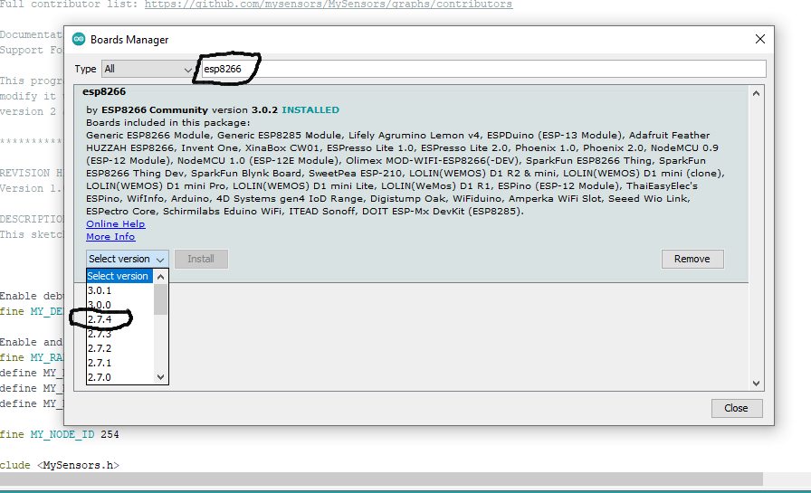
      As MySensors version 2.3.2 and ESP8266 core 3.0.2 combination does not work you need to change one or the other versions.

      The simplest is to roll back the ESP8266 Core version to 2.7.4 and keep the MySensors 2.3.2 version
      (Tools -> Board -> Board Manager)
      Enter ESP8266 in search bar, then click within the ESP8266 data info box, click the select version pulldown.
      Select 2.7.4 and then click Install.

      311c31b0-d056-436f-a3b0-d95cf3099b13-image.png

      Other option is to update the MySensors library to the development version 2.4.0-Alpha but that has to be done manually.

      posted in Troubleshooting
      hard-shovel
      hard-shovel
    • RE: ESP8266Wifi Gateway won't connect

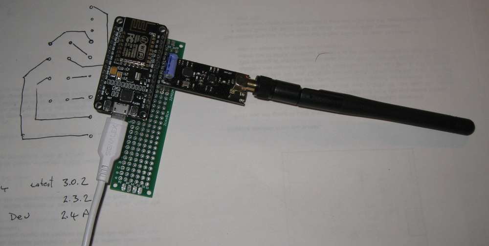
      @dpcons I assembled a board copied from yours for testing.
      Img_9930x.jpg

      I could replicate the problem. It is with the ESP core version and the MySensor Version
      MySensors version 2.3.2 and ESP8266 core 3.0.2 does not work,

      MySensors version 2.3.2 and ESP8266 core 2.7.4 works

      Mysensors development version 2.4.0-Alpha and newest ESP8266 core 3.0.2 also works

      So you can either update the esp core to older version 2.7.4, or install the development version of MySensors 2.4.0-Alpha

      posted in Troubleshooting
      hard-shovel
      hard-shovel
    • RE: ESP8266Wifi Gateway won't connect

      @dpcons As you are seeing no serial debug data. Have you checked that your serial data monitor is set for the same baud rate as set in the sketch (9600 on MySensors GatewayESP8266 sketch) as other sketches use default 115200

      posted in Troubleshooting
      hard-shovel
      hard-shovel
    • RE: Reading INPUTS from arduino in domoticz

      @Mati_Smart

      What troubleshooting steps have you all ready taken?

      I have loaded your sketch onto a mega2560 and looked at the serial output.
      the binary switch child's 20 and 21 are switching.

      0;20;1;0;16;1
      0;21;1;0;16;1
      0;21;1;0;16;0
      0;20;1;0;16;0
      0;21;1;0;16;1
      0;20;1;0;16;1
      0;21;1;0;16;0
      0;21;1;0;16;1
      0;21;1;0;16;0
      0;21;1;0;16;1
      0;20;1;0;16;0
      0;20;1;0;16;1
      

      have you checked this?

      also why do you have all MY_INCLUSION defines active when there is no radio attached?

      // Enable inclusion mode
      #define MY_INCLUSION_MODE_FEATURE
      // Enable Inclusion mode button on gateway
      #define MY_INCLUSION_BUTTON_FEATURE
      
      // Inverses behavior of inclusion button (if using external pullup)
      //#define MY_INCLUSION_BUTTON_EXTERNAL_PULLUP
      
      // Set inclusion mode duration (in seconds)
      #define MY_INCLUSION_MODE_DURATION 60 
      // Digital pin used for inclusion mode button
      #define MY_INCLUSION_MODE_BUTTON_PIN  3 
      

      and you have the repeater function enabled

      // Enable repeater functionality for this node
      #define MY_REPEATER_FEATURE
      

      this is sloppy programming and can cause problems.

      Have you checked the basic things like the connections to the inputs?
      You have the internal PULLUP enabled so the input signal should switch to ground.

      posted in Hardware
      hard-shovel
      hard-shovel
    • RE: Modifying A0 value to Percentage

      @mrhutchinsonmn

      try changing

       moistureLevels[i] = map(moistureLevel,0,650,0,99); // The maximum voltage output of the capacitive sensor is 3V, so since we're measuring 0-5v about 614 is the theoretical highest value we'll ever get.
      

      to

       moistureLevels[i] = map(moistureLevel,325,650,99,0); // The maximum voltage output of the capacitive sensor is 3V, so since we're measuring 0-5v about 614 is the theoretical highest value we'll ever get.
      
      posted in General Discussion
      hard-shovel
      hard-shovel
    • RE: Is V_RGB Supported in OpenHAB?

      Hi

      Openhab and the MySensors binding use the HSTtype format (hue, saturation, brightness) for color information.
      The binding automatically converts the HSBtype to the MySensors format of RRGGBB.
      So you need to use the HSBType fromRGB(int R, int G, int B) function

      items

      Color   Mock_RGB_LED     "Mock RGB LED (HSB)     "  (test254) { channel = "mysensors:rgbLight:gatewayWIFI3:Mock_RGB_LED:rgb" } 
      String  test_RGB_HexString "Test Color RGB hexS [0x%s]" (test254) 
      Number  test_RGB_Red	" Test Colour Red    [%s]"  (test254)
      Number  test_RGB_Green  " Test Colour Green  [%s]"  (test254)
      Number  test_RGB_Blue   " Test Colour Blue   [%s]"  (test254)
      

      Rules

      val String filename = "rgb-light.rules"
      
      rule "System startup"
              when
                      System started
              then
      /*Initial value of colors*/
          if (test_RGB_Red.state == NULL) test_RGB_Red.postUpdate(0)
      	if (test_RGB_Green.state == NULL) test_RGB_Green.postUpdate(0)
          if (test_RGB_Blue.state == NULL) test_RGB_Blue.postUpdate(0)
      end
      rule "Test Colour Channels RGB to Mysensors"
      when
      	Item test_RGB_Red   changed or
      	Item test_RGB_Green changed or
      	Item test_RGB_Blue  changed
      then
          val int r = (test_RGB_Red.state as Number).intValue
          val int g = (test_RGB_Green.state as Number).intValue
          val int b = (test_RGB_Blue.state as Number).intValue
          logInfo(filename, "Input Conversion: r:" + r + " g:" + g + " b:" + b)
         var HSBType hsb = HSBType.fromRGB(r, g, b)
          logInfo(filename, "Input Conversion: hsb" + hsb)	
          Mock_RGB_LED.sendCommand(hsb)
      end
      
      
      rule "RGB Hex -> HSB"
      when
          Item test_RGB_HexString received update
      then
          var rgb = test_RGB_HexString.state.toString
      
          var r = Integer::parseInt(rgb.substring(0, 2), 16)
          var g = Integer::parseInt(rgb.substring(2, 4), 16)
          var b = Integer::parseInt(rgb.substring(4, 6), 16)
      
          logInfo(filename, "Input Conversion: r" + r + " g" + g + " b" + b)
          var HSBType hsb = HSBType.fromRGB(r, g, b)
          logInfo(filename, "Input Conversion: hsb" + hsb)
          
          Mock_RGB_LED.sendCommand(hsb)	
      end
      
      /* I find this most useful for testing the node the Node */
      rule "Test Colour Channels RGB to Mysensors"
      when
          Item test_RGB_Red   changed or
          Item test_RGB_Green changed or
          Item test_RGB_Blue  changed
      then
          var int r = (test_RGB_Red.state as Number).intValue
          var int g = (test_RGB_Green.state as Number).intValue
          var int b = (test_RGB_Blue.state as Number).intValue
          logInfo(filename, "Input Conversion: r:" + r + " g:" + g + " b:" + b)
          var HSBType hsb = HSBType.fromRGB(r, g, b)
          logInfo(filename, "Input Conversion: hsb" + hsb)	
          Mock_RGB_LED.sendCommand(hsb)
      end	


      posted in OpenHAB
      hard-shovel
      hard-shovel
    • RE: OpenHAB MySensors binding 2.5: V_VAR1 and String values

      I have tried this on my test system and i get the same results as you using the VAR1 -- VAR5 with the cover (RollerShutter) thing.

      However if you add CustomSensor thing to your node then using the VAR1-VAR5 work as expected with the mapping. With numbers to and from the node.

      things

      cover    Mock_Cover        [nodeId=254, childId=6 ]
      text     Mock_info         [nodeId=254, childId=7 ]
      

      Items

      Rollershutter	Mock_Cover_State       "Mock Cover State       [%s]"   <rollershutter>     (test254) { channel = "mysensors:cover:gatewayWIFI3:Mock_Cover:cover" } 
      
      Number  Mock_Info_Var1			"Mock Info Variable 1 (number) [%s]"                        (test254) { channel = "mysensors:text:gatewayWIFI3:Mock_Info:var1" }
      String  Mock_Info_Var1s			"Mock Info Variable 1 (string) [%s]"                        (test254) { channel = "mysensors:text:gatewayWIFI3:Mock_Info:var1" }
      Number  Mock_Info_Var1m			"Mock Info Variable 1 (number) [MAP(curtains.map):%s]"      (test254) { channel = "mysensors:text:gatewayWIFI3:Mock_Info:var1" }
      String  Mock_Info_Var1sm        "Mock Info Variable 1 (string map) [%s]" (test254) { channel="mysensors:text:gatewayWIFI3:Mock_Info:var1" [profile="transform:MAP", function="curtains.map"]  } 
      Number  Mock_Info_Var2			"Mock Info Variable 2 (number) [%s]"                        (test254) { channel = "mysensors:text:gatewayWIFI3:Mock_Info:var2" }
      Number  Mock_Info_Var3			"Mock Info Variable 3 (number) [%s]"                        (test254) { channel = "mysensors:text:gatewayWIFI3:Mock_Info:var3" }
      Number  Mock_Info_Var4			"Mock Info Variable 4 (number) [%s]"                        (test254) { channel = "mysensors:text:gatewayWIFI3:Mock_Info:var4" }
      Number  Mock_Info_Var5			"Mock Info Variable 5 (number) [%s]"                        (test254) { channel = "mysensors:text:gatewayWIFI3:Mock_Info:var5" }
      

      Node

      #define CHILD_ID_COVER 6
      #define CHILD_ID_CUSTOM 7
      
      present(CHILD_ID_COVER, S_COVER, "Roller Shutters");
      present(CHILD_ID_CUSTOM, S_CUSTOM, "Reasons");
      

      Or you if you want to send strings you could use

      String  Mock_Info_Text			"Mock Info text sting [%s] "                                (test254) { channel = "mysensors:text:gatewayWIFI3:Mock_Info:text" }
      
      posted in OpenHAB
      hard-shovel
      hard-shovel
    • RE: OpenHAB MySensors binding 2.5: V_VAR1 and String values

      Just use the V_Var1-5 to send a number to the node ( saves bandwidth) and back then use the MAP transform function to shown the human readable strings.

      Make sure you have the Map Transformation installed in Transformations add-ons

      The add a mapping file in the transformation folder

      example file blinds.map

      NULL=unknown Reason
      -=unknown Reason
      0=initial
      1=Closed for Sunset
      2=Closed for Sun Protection
      3=Closed for Sleeping
      4=Closed for Alexa Command
      5=Closed for User Command
      6=Closed for Security
      7=Closed for Privacy
      8=Closed for Migraine
      9=Closed due to schedule
      10 = Closed due to riots
      
      33=Open for Sunrise
      34=Open Ended Sun Protection
      35=Open for Wakeup
      36=Open for Alexa Command
      37=Open for User Command
      38=Open for Security
      39=Open for No Privacy
      40=Open for end of Migraine 
      41=Open due to schedule
      
      initial = 0
      Closed for Sunset =1
      Closed for Sun Protection = 2
      Closed for Sleeping = 3
      Closed for Alexa Command = 4
      Closed for User Command = 5
      Closed for Securitry = 6
      Closed for Privacy = 7
      Closed for Migraine = 8
      Closed due to schedule = 9
      
      Open for Sunrise = 33
      Open Sun Protection Ended = 34
      Open for Wakeup = 35
      Open for Alexa Command = 36
      Open for User Command = 37
      Open for Securitry = 38
      Open for No Privacy = 39
      open end of Migraine = 40 
      open due to schedule = 41


      add the map transformation to item

      Sample Items

      // Blind Nodes 234,235,236
      Number Blinds1_Reason	 "Bedroom 1 Blinds  [MAP(blinds.map):%s]"  (blinds, test1)  { channel = "mysensors:customSensor:gatewayWIFI2:Blinds234:var1" }
      Number Blinds2_Reason	 "Bedroom 2 Blinds  [MAP(blinds.map):%s]"  (blinds, test1)  { channel = "mysensors:customSensor:gatewayWIFI2:Blinds235:var1" }
      Number Blinds3_Reason	 "Bedroom 3 Blinds  [MAP(blinds.map):%s]"  (blinds, test1)  { channel = "mysensors:customSensor:gatewayW5100:Blinds236:var1" }
      

      see https://www.openhab.org/addons/transformations/map/ for full details.

      posted in OpenHAB
      hard-shovel
      hard-shovel
    • RE: Sensor required to detect PVC insulated COPPER wire

      @yemesvee
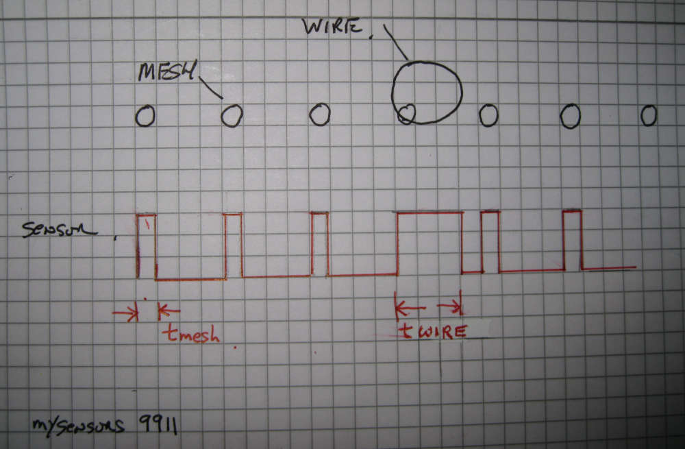
      If using a digital sensor mounted as per Kimot diagram you will receive a pulse stream, check the width of the pulsed to find if mesh or cable.

      0_1546463575890_Img_4675x.jpg

      use the function pulseIn to determine the pulse width.


      The simple example of the time duration of a pulse
      
      int SensorPin = 3;
      unsigned long duration = 0;
      unsigned long CableDuration = 100;     // Set to suitable value
      unsigned long CableCount = 0;
      
      void setup()
      {
        pinMode(SensorPin , INPUT);
      }
      
      void loop()
      {
      
        duration = pulseIn(SensorPin , HIGH);
        Serial.print("Duration  : ");
        Serial.println(duration);
        if (duration >= CableDuration) {
          ++ CableCount;
          Serial.print("Cable detection  :");
          Serial.println(CableCount);
        }
      }


      posted in My Project
      hard-shovel
      hard-shovel
    • RE: Sensors error

      @ek-wik you are describing sensor repeatability,

      posted in General Discussion
      hard-shovel
      hard-shovel
    • RE: Multiple Dallas Temperatuur sensors at one sensor node

      @dzjr To get the extra resolution sent to the controller try using

        send(msg.setSensor(i+21).set(temperature,2));
      posted in Troubleshooting
      hard-shovel
      hard-shovel
    • RE: Sensor required to detect PVC insulated COPPER wire

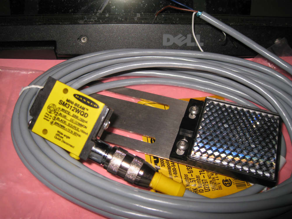
      If the mesh moves at constant speed, How about a simple optical IR Sensor (break beam or Reflective), then checking pulse width of signal to detect mesh vs cable. Otherwise synchronize pulse width detection ratio in correlation to mesh speed.

      Similar to this
      0_1543047362376_IMG_4549.JPG

      posted in My Project
      hard-shovel
      hard-shovel
    • RE: Is it really required to remove the voltage regulator to save power?

      @benhub Short answers, No, Yes, Yes

      The regulator will use power if connected.
      If your circuit is power hungry then removing the regulator will have limited effect.
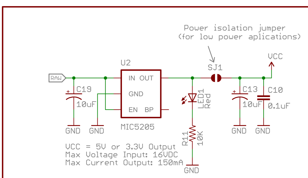
      The sparkfun schematic on the article that you listed notes to disconnect the regulator for low power, so the advice is consistent.
      Unless you are using the genuine sparkfun versions of the pro-mini where the jumper can be cut then physically removing the regulator is recommended.
      0_1542936362010_Arduino-Pro-Mini-v14 regulator part.png

      posted in Hardware
      hard-shovel
      hard-shovel
    • RE: Multiple Dallas Temperatuur sensors at one sensor node

      @dzjr you have the define

      #define TEMPERATURE_PRECISION 12
      

      In the github code this is not utilized, so the sensors are operating in 9 bit resolution.

      You need to add the following in the before or setup

      sensors.setResolution(TEMPERATURE_PRECISION);
      
      posted in Troubleshooting
      hard-shovel
      hard-shovel
    • RE: Driving an moving coil meter whit a PWM output

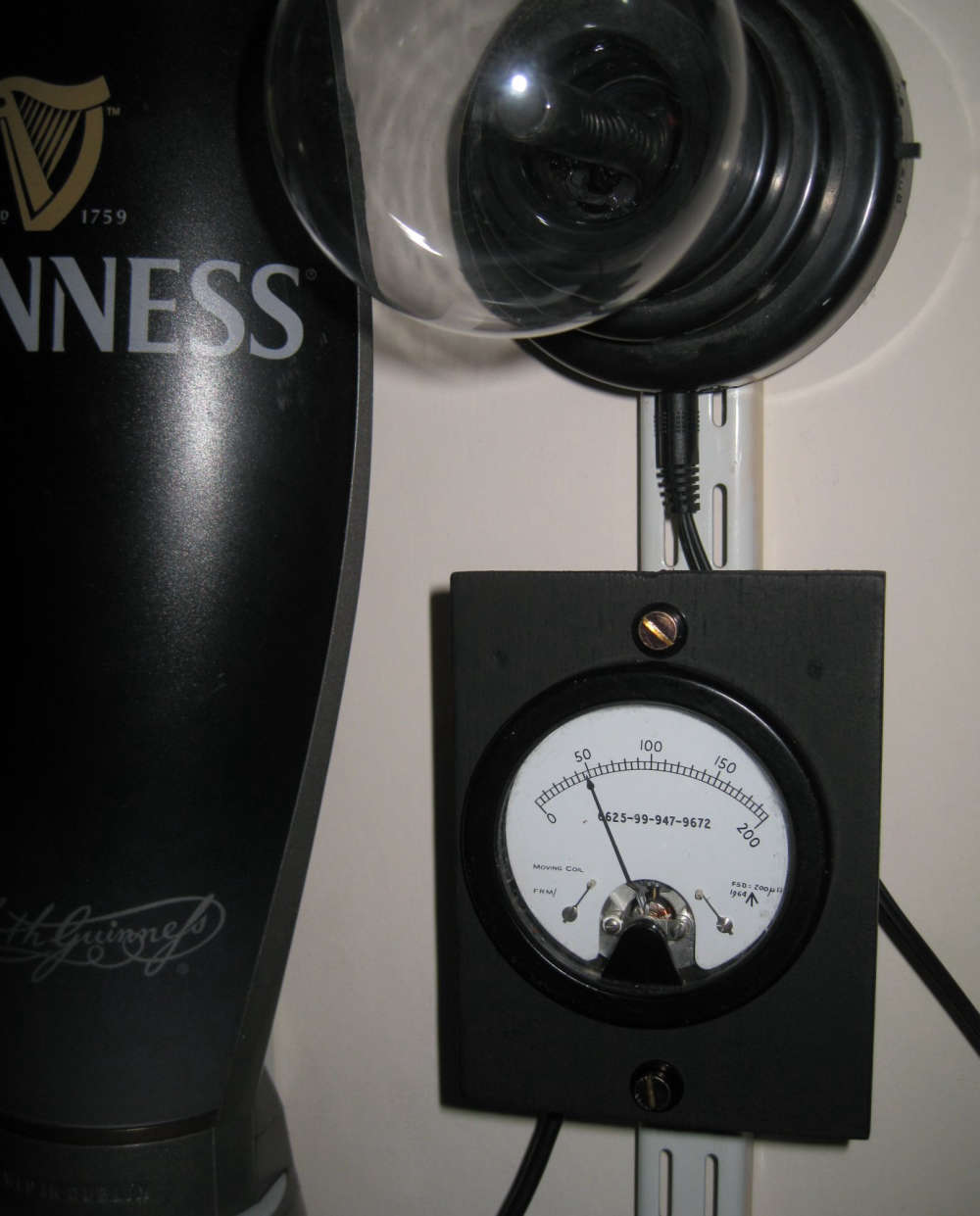
      @dzjr I also have various old meters, Some have a sealed movement so unable to change the scales.

      Below is my meter showing time since last coffee.
      0_1539880962040_Img_4463x.jpg

      posted in Hardware
      hard-shovel
      hard-shovel
    • RE: 💬 Dimmable LED Actuator

      @mateos78
      Attached is a sketch that i have just tried with domoticz (running on a windows test machine) It works fine when used as a node with a gateway. Encoder/ Switch and webpage slider/switch operating.

      However when set up as a single gateway node as your sketch, only the encoder function works, you can vary the lamp level from the slider or the encoder, but the domaticz on/off or the button does not operate correctly. it seems to be the way the messages are acknowledged

      I also find that when i change the led dimmer from the encoder the led changes quickly, but it take about ten seconds before the dormoticz web page updates to show each new slider position.

      The following Sketch needs the #define OPENHAB2 defined for use with openhab and undefined for Dormoticz

      /**
       * The MySensors Arduino library handles the wireless radio link and protocol
       * between your home built sensors/actuators and HA controller of choice.
       * The sensors forms a self healing radio network with optional repeaters. Each
       * repeater and gateway builds a routing tables in EEPROM which keeps track of the
       * network topology allowing messages to be routed to nodes.
       *
       * Created by Henrik Ekblad <henrik.ekblad@mysensors.org>
       * Copyright (C) 2013-2015 Sensnology AB
       * Full contributor list: https://github.com/mysensors/Arduino/graphs/contributors
       *
       * Documentation: http://www.mysensors.org
       * Support Forum: http://forum.mysensors.org
       *
       * This program is free software; you can redistribute it and/or
       * modify it under the terms of the GNU General Public License
       * version 2 as published by the Free Software Foundation.
       *
       *******************************
       * DESCRIPTION
       * This sketch provides an example how to implement a dimmable led light node with a rotary 
       * encoder connected for adjusting light level. 
       * The encoder has a click button which turns on/off the light (and remembers last dim-level) 
       * The sketch fades the light (non-blocking) to the desired level. 
       *
       * Default MOSFET pin is 3
       * 
       *  Arduino      Encoder module
       *  ---------------------------
       *  5V           5V (+)  
       *  GND          GND (-)
       *  4            CLK (or putput 1)
       *  5            DT  (or output 1) 
       *  6            SW (Switch/Click)  
       *
       *  For OpenHAB2  enable @define OPENHAB2
       *  
       *  NOTE
       *  PROBLEM: 
       *  Using as a Gateway Node With Dormoticz the SWITCH ON/OFF DOES not work correcly either from the controller or by the Encoder 
       *  Using as a normal node all functions operate correctly.
       *  
        */
       /
      
       
      // Enable debug prints
      //#define MY_DEBUG


      // --- Enable Serial Gateway Transport
      #define MY_GATEWAY_SERIAL
      //#define MY_INCLUSION_MODE_FEATURE
      //#define MY_INCLUSION_BUTTON_FEATURE
      //#define MY_INCLUSION_MODE_DURATION 60
      //#define MY_INCLUSION_MODE_BUTTON_PIN 8
      
      
      // --- Enable RS485 transport layer
      //#define MY_RS485
      // Define this to enables DE-pin management on defined pin
      //#define MY_RS485_DE_PIN 12
      // Set RS485 baud rate to use
      //#define MY_RS485_BAUD_RATE 9600


      // Enable and select radio type attached
      //#define MY_RADIO_NRF24
      //#define MY_RADIO_RFM69
      
      #include <SPI.h>
      #include <MySensors.h>  
      #include <Bounce2.h>
      #include <Encoder.h>
      
      #define LED_PIN 3           // Arduino pin attached to MOSFET Gate pin
      #define KNOB_ENC_PIN_1 4    // Rotary encoder input pin 1
      #define KNOB_ENC_PIN_2 5    // Rotary encoder input pin 2
      #define KNOB_BUTTON_PIN 6   // Rotary encoder button pin 
      #define FADE_DELAY 10       // Delay in ms for each percentage fade up/down (10ms = 1s full-range dim)
      #define SEND_THROTTLE_DELAY 400 // Number of milliseconds before sending after user stops turning knob
      #define SN "DimmableLED /w button"
      #define SV "1.3a"
      
      #define CHILD_ID_LIGHT 1
      
      #define EEPROM_DIM_LEVEL_LAST 1
      #define EEPROM_DIM_LEVEL_SAVE 2
      // #define OPENHAB2                      // Use Define if using OPENHAB2 
      
      #define LIGHT_OFF 0
      #define LIGHT_ON 1
      
      int dimValue;
      int fadeTo;
      int fadeDelta;
      byte oldButtonVal;
      bool changedByKnob=false;
      bool sendDimValue=false;
      unsigned long lastFadeStep;
      unsigned long sendDimTimeout;
      char convBuffer[10];
      
      MyMessage dimmerMsg(CHILD_ID_LIGHT, V_DIMMER);
      MyMessage statusMsg(CHILD_ID_LIGHT, V_STATUS);    // Addition for Status update to OpenHAB Controller
      Encoder knob(KNOB_ENC_PIN_1, KNOB_ENC_PIN_2);  
      Bounce debouncer = Bounce(); 
      
      void setup()  
      { 
        // Set knob button pin as input (with debounce)
        pinMode(KNOB_BUTTON_PIN, INPUT);
        digitalWrite(KNOB_BUTTON_PIN, HIGH);
        debouncer.attach(KNOB_BUTTON_PIN);
        debouncer.interval(5);
        oldButtonVal = debouncer.read();
      
        // Set analog led pin to off
        analogWrite( LED_PIN, 0);
      
        // Retreive our last dim levels from the eprom
        fadeTo = dimValue = 0;
        byte oldLevel = loadLevelState(EEPROM_DIM_LEVEL_LAST);
        Serial.print("Sending in last known light level to controller: ");
        Serial.println(oldLevel);  
        send(dimmerMsg.set(oldLevel), true);
        Serial.println("Ready to receive messages...");  
      }
      
      void presentation() {
        // Send the Sketch Version Information to the Gateway
        present(CHILD_ID_LIGHT, S_DIMMER);
        sendSketchInfo(SN, SV);
      }
      
      void loop()      
      {
        // Check if someone turned the rotary encode
        checkRotaryEncoder();
        
        // Check if someone has pressed the knob button
        checkButtonClick();
        
        // Fade light to new dim value
        fadeStep();
      }
      
      void receive(const MyMessage &message)
      {
          #ifdef MY_DEBUG
          // This is called when a message is received 
          Serial.print("Message: "); Serial.print(message.sensor); Serial.print(", type: "); Serial.print(message.type); Serial.print(", Message: ");
          #endif
          
        if (message.type == V_STATUS) {
          // Incoming on/off command sent from controller ("1" or "0")
          int lightState = message.getString()[0] == '1';
          int newLevel = 0;
          if (lightState==LIGHT_ON) {
            // Pick up last saved dimmer level from the eeprom
            newLevel = loadLevelState(EEPROM_DIM_LEVEL_SAVE);
          } else {
            
          }
          // Send dimmer level back to controller with ack enabled
          send(dimmerMsg.set(newLevel), true);
          // We do not change any levels here until ack comes back from gateway 
          return;
        } else if (message.type == V_PERCENTAGE) {
          // Incoming dim-level command sent from controller (or ack message)
          fadeTo = atoi(message.getString(convBuffer));
          // Save received dim value to eeprom (unless turned off). Will be
          // retreived when a on command comes in
          if (fadeTo != 0)
            saveLevelState(EEPROM_DIM_LEVEL_SAVE, fadeTo);
        }
        saveLevelState(EEPROM_DIM_LEVEL_LAST, fadeTo);
        #ifdef MY_DEBUG
        Serial.print("New light level received: ");
        Serial.println(fadeTo);
        #endif
        
        if (!changedByKnob) 
          knob.write(fadeTo<<1);             //### need to multiply by two (using Shift left)
          
        // Cancel send if user turns knob while message comes in
        changedByKnob = false;
        sendDimValue = false;
      
        // Stard fading to new light level
        startFade();
      }


      void checkRotaryEncoder() {
        long encoderValue = knob.read()>>1 ;      //### Divide by 2 (using shift right) 
      
        if (encoderValue > 100) {   
          encoderValue = 100;       
          knob.write(200);                        //### max value now 200 due to divide by 2
        } else if (encoderValue < 0) {
          encoderValue = 0;
          knob.write(0);
        }
      
        if (encoderValue != fadeTo) {    
          fadeTo = encoderValue;                   
          changedByKnob = true;
          startFade();
        }
      }
      
      void checkButtonClick() {
        debouncer.update();
        byte buttonVal = debouncer.read();
        byte newLevel = 0;
        if (buttonVal != oldButtonVal && buttonVal == LOW) {
          if (dimValue==0) {
            // Turn on light. Set the level to last saved dim value
            int saved = loadLevelState(EEPROM_DIM_LEVEL_SAVE);
            newLevel = saved > 1 ? saved : 100;           // newLevel = saved > 0 ? saved : 100;     
          } 
          send(dimmerMsg.set(newLevel),true);
          #ifdef OPENHAB2
          send(statusMsg.set(newLevel>0 ? "1" : "0")); // Addition for Status update to OpenHAB Controller,   No Echo
          #endif
        }
        oldButtonVal = buttonVal;
      }
      
      void startFade() {
        fadeDelta = ( fadeTo - dimValue ) < 0 ? -1 : 1;
        lastFadeStep = millis();
      }
      
      // This method provides a graceful none-blocking fade up/down effect
      void fadeStep() {
        unsigned long currentTime  = millis();
      
        if ( dimValue != fadeTo && currentTime > lastFadeStep + FADE_DELAY) {
          dimValue += fadeDelta;
          analogWrite( LED_PIN, (int)(dimValue / 100. * 255) );
          lastFadeStep = currentTime;
          #ifdef MY_DEBUG
          Serial.print("Fading level: ");
          Serial.println(dimValue);
          #endif
          
          if (fadeTo == dimValue && changedByKnob) {
            sendDimValue = true;
            sendDimTimeout = currentTime;
          }
        } 
        // Wait a few millisecs before sending in new value (if user still turns the knob)
        if (sendDimValue && currentTime > sendDimTimeout + SEND_THROTTLE_DELAY)  {
           // We're done fading.. send in new dim-value to controller.
           // Send in new dim value with ack (will be picked up in incomingMessage) 
          send(dimmerMsg.set(dimValue), true); // Send new dimmer value and request ack back
          sendDimValue = false;
        }
      }
      
      // Make sure only to store/fetch values in the range 0-100 from eeprom
      int loadLevelState(byte pos) {
        return min(max(loadState(pos),0),100);
      }
      void saveLevelState(byte pos, byte data) {
        saveState(pos,min(max(data,0),100));
      }
      

      I maybe overlooking something obvious as i only have a couple of hours experience with domoticz.

      posted in Announcements
      hard-shovel
      hard-shovel
    • RE: 💬 Dimmable LED Actuator

      @mateos78 See https://forum.mysensors.org/topic/9670/problem-with-dimmable-led-actuator-with-encoder/11

      posted in Announcements
      hard-shovel
      hard-shovel
    • RE: 💬 PogoPins

      I made a simple adapter for Pro Minis, Used on it own for new boards with connection holes
      0_1539605590332_Img_4455y.jpg

      If you slide on some dupont cable covers as a guide it makes it easy to program a soldered board
      0_1539605765924_Img_4456y.jpg

      0_1539605916766_Img_4462y.jpg

      0_1539606003550_Img_4457y.jpg

      posted in OpenHardware.io
      hard-shovel
      hard-shovel
    • RE: Only a hard reset works.

      @robert the NUMBER_OF_RELAYS is already defined in your sketch, just use as pasted.

      I use OpenHAB so i just tried to install Dormotiz and was supreised that it took less than a an hour to install and get working with the relays. (Most of that time was trying to get them to shown up on the dashboard)

      Dormotiz is communication fine with my node and i can switch on and off the relays from the Dashboard

      0_1539548686702_Domoricz RS485 3.png

      In the sort time i have checked i do see that the Last Seen time only changes when i change the state of the relay.

      So your program that you posted works for me with both my normal OpenHAB and the new test Domoticz.

      I think that i may be miss understanding your actual problem.

      posted in General Discussion
      hard-shovel
      hard-shovel
    • RE: ENC28J60 Gateway - no ping

      @daniele-frigo

      I have tried the stable and development versions of my sensors, the standard UIPEthernet.h and the Mysensors version of UIPEthernet.h, and several versions of Arduino IDE and still cannot replicate your log result of getting only one line of debug data using your program.

      This should generate five lines of debug code regardless if the ENC module is connected.
      With the module connected you should be able to ping the arduino on 192.168.1.22 if your computer is on the same subnet.

      So several questions & things to consider
      1 Are you actually testing using the code you posted above and getting only the one line of debug
      If so, then I think you need to check your software versions,
      1a Are you using Arduino IDE or some other environment like PlatformIO what versions?
      1b Is the correct UIPEthernet.h being used during compiling?
      1c Are there any error messages during compiling, what is the memory usage?
      1d what bootloader are you using? the Old nano Bootloader, New nano type or some other?

      2 Is the network address suitable for your network and you have no other item using that ip address and no arduino device using the same MAC address
      for pinging Is your computer on the same subnet ie 192.168.1.xxx

      3 My ENC modules are power hungry they take about 150mA with only a nano attached. Is you power supply sufficient and smooth?

      4 Are you plugging the board to the nano or using jumpers?
      If using jumpers try and jumper from the Nano pin 10(CS) to pin 8 on the board it is possible the board has the cs connection on pin 8.

      5 You could try loading the UIPEthernet example EchoServer and see if you can then get echo back from your computer if you use telnet on your computer.
      When doing this use a suitable MAC, IP address and port number on the arduino for your computer network.
      This example uses the same connections as the gateway so no wiring changes.
      You should then be able to connect and then get text sent from the computer echoed back from the arduino using telnet.

      6 Failed Parts!
      Original Nano
      If you were powering the original nano from the USB port then i suspect the input diode has partially failed, so will supply very limited power to the board from the USB connector, If you were powering the nano via the RAW pin then the voltage regulator is suspect.

      ENC28J60 Board
      If the Link and Data LEDs are lighting up then the ENC28J60 is working to some extent as these LEDs are controlled by the chip.

      So I suspect the programing and then power / connections.

      Of course even if you get this working this chip is second rate compared to the W5100 or W5500 in both memory consumption and speed.

      posted in Hardware
      hard-shovel
      hard-shovel
    • RE: Combining DS18B20 and relay..

      @mela You are presenting the devices as Relay Child 1, and Temperature sensors as Child Ids 5 and 6.

      But when sending you are sending the temperatures as Child Ids 0 and 1

      Change the following send line

            // Send in the new temperature
            send(msg.setSensor(i).set(temperature,1));
      

      to

            // Send in the new temperature
            send(msg.setSensor(i+5).set(temperature,1));
      

      so the send function matches the presentation values.

      posted in Troubleshooting
      hard-shovel
      hard-shovel
    • RE: ENC28J60 Gateway - no ping

      @daniele-frigo I have just tried my setup again using Mysensor 2.3.0 and I still get the same debug and ping response.

      I also get the same five lines of debug output even if the ENC28J60 is not connected. So i wonder why your output is only one line with the same code above!

      If I power my ENC28J60 with only +5V and GND and no other connections
      I get the Power LED on and then with a network cable connected the Green Link LED solid ON at the network connector and random blinking of the Yellow traffic LED

      So you could have a problem with the Power or Regulator on your board.

      posted in Hardware
      hard-shovel
      hard-shovel
    • RE: Longer text in V_TEXT, any workarounds?

      @dakipro I whould send a line number for each part of the text and some sort of EOL character to indicate the end.

      [CS] this is some 24 message th
      [02] at is being split over multipl
      [03] e messages [EOL]

      So if message [03] arrived without [02] you could request a resend.

      posted in Development
      hard-shovel
      hard-shovel
    • RE: Driving an moving coil meter whit a PWM output

      @dzjr I have several meters for quick indications.

      Normally i utilize a message type of V_VAR1 to 5 as these are available for all sensor types, If it just being an information sensor then I use the S_INFO device.

      I send the information to be displayed as direct units
      For example for temperature I would send V_VAR1 = 26.1 as 26.1°C or -5.5
      and then let the node set the display range.

      if you want only a linear display the following code will work,

      // Enable debug prints to serial monitor
      #define MY_DEBUG
      
      // Enable and select radio type attached
      #define MY_RADIO_NRF24
      
      #include <MySensors.h>
      
      #define SKETCH_NAME "MySensors Meter"
      #define SKETCH_VERSION "v1.0"
      
      // Meter Vars
      #define METER_PIN     5
      #define METER_ID      20    // whater childId your using
      #define METER_MIN      0    // meter Minimum value
      #define METER_MAX     30    
      MyMessage msg_S_INFO_VAR1(ID_S_INFO,V_VAR1);
      float info_Var1 = 00.0;
      
      void before()
      {
      }
      
      void setup() {
        // put your setup code here, to run once:
      
      }
      
      void loop() {
        // put your main code here, to run repeatedly:
      
      }
      
      void receive(const MyMessage &message)
      { 
        if (message.type == V.VAR1) {
            info_Var1=message.getFloat();
          Serial.print("Incoming value for ID_S_INFO:");
          Serial.print(message.sensor);
          Serial.print(", V_VAR1: ");
          Serial.print(", New status: ");
          Serial.println(info_Var1,1);
          updateMeter0(info_Var1);
        }
      }
      
      
      void updateMeter0(float meterInput=0){
      // Meter 0   this uses the input value and simple maping
      // Note The map() function uses integer math so will not generate fractions, so can be helpful to multiply input values
      // ie using input temperature value 0 to 30°C  So multiply by 10 to get 0-to 300
      int16_t max_Output=   255;   // maximum PWM Value, 255 for Arduino Uno,  1023 for ESP8266
      meterInput = meterInput *10;
      analogWrite(meter_pin, map(meterInput,meter_MIN, meter_MAX, 0, max_Output )) ;  // map to Max PWM Level        
      }


      However i like to have arbitrary scales so normally use a look-up array for the pwm values. as used in the meters shown.

      0_1538783259128_IMG_4446.JPG

      posted in Hardware
      hard-shovel
      hard-shovel
    • RE: ENC28J60 Gateway - no ping

      @daniele-frigo
      I have just tried your code with the separate module type ENC28J60 and get the following Debug output, and pinging is successful.

      0 MCO:BGN:INIT GW,CP=R-NGA---,VER=2.3.1-alpha
      54 GWT:TIN:IP=192.168.1.22
      1056 MCO:BGN:STP
      1058 MCO:REG:NOT NEEDED
      1060 MCO:BGN:INIT OK,TSP=NA
      

      I only have the following connected
      +5V, GND, SO-12, SCK-13, SI-11, CS-10 (INT-2, RESET-RESET)

      Have you tried unplugging the nano from the ENC28J60 Shield and just using the above jumpers?

      My module also has CLK and WOL that are unconnected, Could it be that your module has these connected somehow?

      posted in Hardware
      hard-shovel
      hard-shovel
    • RE: Only a hard reset works.

      @robert I have tried your Node sketch and it works fine with my gateway, I am using development branch 2.3.1-alpha.

      Your listing is the same as my unit, gateway stats and the node presents data to the gateway.

      If you are expecting anything else then the controller will have to send some command. Your log file shows no commands from the controller.
      I am using openHAB and it works as expected switching the relay outputs.

      Are you sure your domoticz is sending switching information?

      my Gateway Log, of Gateway startup and Node Presentation

      0 MCO:BGN:INIT GW,CP=RSNGA---,VER=2.3.1-alpha
      4 TSM:INIT
      5 TSF:WUR:MS=0
      6 TSM:INIT:TSP OK
      7 TSM:INIT:GW MODE
      9 TSM:READY:ID=0,PAR=0,DIS=0
      12 MCO:REG:NOT NEEDED
      314 GWT:TIN:IP=192.168.1.152
      1316 MCO:BGN:STP
      1318 MCO:BGN:INIT OK,TSP=1
      1320 TSM:READY:NWD REQ
      1340 TSF:MSG:SEND,0-0-255-255,s=255,c=3,t=20,pt=0,l=0,sg=0,ft=0,st=OK:
      1723 TSF:MSG:READ,10-10-0,s=255,c=3,t=21,pt=1,l=1,sg=0:0
      1748 TSF:MSG:READ,0-10-255,s=255,c=3,t=20,pt=0,l=0,sg=0:
      1754 TSF:MSG:BC
      12392 TSF:MSG:READ,10-10-255,s=255,c=3,t=7,pt=0,l=0,sg=0:
      12397 TSF:MSG:BC
      12399 TSF:MSG:FPAR REQ,ID=10
      12401 TSF:PNG:SEND,TO=0
      12404 TSF:CKU:OK
      12405 TSF:MSG:GWL OK
      12552 TSF:MSG:SEND,0-0-10-10,s=255,c=3,t=8,pt=1,l=1,sg=0,ft=0,st=OK:0
      14423 TSF:MSG:READ,10-10-0,s=255,c=3,t=24,pt=1,l=1,sg=0:1
      14428 TSF:MSG:PINGED,ID=10,HP=1
      14457 TSF:MSG:SEND,0-0-10-10,s=255,c=3,t=25,pt=1,l=1,sg=0,ft=0,st=OK:1
      14488 TSF:MSG:READ,10-10-0,s=255,c=3,t=15,pt=6,l=2,sg=0:0100
      14514 TSF:MSG:SEND,0-0-10-10,s=255,c=3,t=15,pt=6,l=2,sg=0,ft=0,st=OK:0100
      14547 TSF:MSG:READ,10-10-0,s=255,c=0,t=18,pt=0,l=11,sg=0:2.3.1-alpha
      14572 TSF:MSG:READ,10-10-0,s=255,c=3,t=6,pt=1,l=1,sg=0:0
      16600 TSF:MSG:READ,10-10-0,s=255,c=3,t=11,pt=0,l=5,sg=0:Relay
      16626 TSF:MSG:READ,10-10-0,s=255,c=3,t=12,pt=0,l=3,sg=0:1.0
      16650 TSF:MSG:READ,10-10-0,s=1,c=0,t=3,pt=0,l=0,sg=0:
      16672 TSF:MSG:READ,10-10-0,s=2,c=0,t=3,pt=0,l=0,sg=0:
      16695 TSF:MSG:READ,10-10-0,s=3,c=0,t=3,pt=0,l=0,sg=0:
      16717 TSF:MSG:READ,10-10-0,s=4,c=0,t=3,pt=0,l=0,sg=0:
      16740 TSF:MSG:READ,10-10-0,s=5,c=0,t=3,pt=0,l=0,sg=0:
      16762 TSF:MSG:READ,10-10-0,s=6,c=0,t=3,pt=0,l=0,sg=0:
      16788 TSF:MSG:READ,10-10-0,s=255,c=3,t=26,pt=1,l=1,sg=0:2
      16825 TSF:MSG:SEND,0-0-10-10,s=255,c=3,t=27,pt=1,l=1,sg=0,ft=0,st=OK:1
      

      Gateway and node then wait for data from controller then the gateway forwards the information to the node for the relays to operate

      21545 GWT:TSA:ETH OK
      21553 GWT:RFC:MSG=0;0;3;0;2;
      21558 GWT:RFC:MSG=
      38531 GWT:RFC:MSG=10;1;1;0;2;1
      38551 TSF:MSG:SEND,0-0-10-10,s=1,c=1,t=2,pt=0,l=1,sg=0,ft=0,st=OK:1
      38558 GWT:RFC:MSG=
      40156 GWT:RFC:MSG=10;1;1;0;2;0
      40177 TSF:MSG:SEND,0-0-10-10,s=1,c=1,t=2,pt=0,l=1,sg=0,ft=0,st=OK:0
      40183 GWT:RFC:MSG=
      41359 GWT:RFC:MSG=10;1;1;0;2;1
      41379 TSF:MSG:SEND,0-0-10-10,s=1,c=1,t=2,pt=0,l=1,sg=0,ft=0,st=OK:1
      41385 GWT:RFC:MSG=
      42444 GWT:RFC:MSG=10;1;1;0;2;0
      42465 TSF:MSG:SEND,0-0-10-10,s=1,c=1,t=2,pt=0,l=1,sg=0,ft=0,st=OK:0
      42472 GWT:RFC:MSG=
      43549 GWT:RFC:MSG=10;1;1;0;2;1
      43570 TSF:MSG:SEND,0-0-10-10,s=1,c=1,t=2,pt=0,l=1,sg=0,ft=0,st=OK:1
      43576 GWT:RFC:MSG=
      44527 GWT:RFC:MSG=10;1;1;0;2;0
      44548 TSF:MSG:SEND,0-0-10-10,s=1,c=1,t=2,pt=0,l=1,sg=0,ft=0,st=OK:0
      44555 GWT:RFC:MSG=
      45376 GWT:RFC:MSG=10;1;1;0;2;1
      45396 TSF:MSG:SEND,0-0-10-10,s=1,c=1,t=2,pt=0,l=1,sg=0,ft=0,st=OK:1
      45404 GWT:RFC:MSG=
      46257 GWT:RFC:MSG=10;1;1;0;2;0
      46278 TSF:MSG:SEND,0-0-10-10,s=1,c=1,t=2,pt=0,l=1,sg=0,ft=0,st=OK:0
      46284 GWT:RFC:MSG=
      47184 GWT:RFC:MSG=10;1;1;0;2;1
      47205 TSF:MSG:SEND,0-0-10-10,s=1,c=1,t=2,pt=0,l=1,sg=0,ft=0,st=OK:1
      47211 GWT:RFC:MSG=
      48029 GWT:RFC:MSG=10;1;1;0;2;0
      48050 TSF:MSG:SEND,0-0-10-10,s=1,c=1,t=2,pt=0,l=1,sg=0,ft=0,st=OK:0
      48057 GWT:RFC:MSG=
      50527 GWT:RFC:MSG=10;2;1;0;2;1
      50547 TSF:MSG:SEND,0-0-10-10,s=2,c=1,t=2,pt=0,l=1,sg=0,ft=0,st=OK:1
      50554 GWT:RFC:MSG=
      51294 GWT:RFC:MSG=10;2;1;0;2;0
      51314 TSF:MSG:SEND,0-0-10-10,s=2,c=1,t=2,pt=0,l=1,sg=0,ft=0,st=OK:0
      51320 GWT:RFC:MSG=
      

      Node Debug Log

      7 MCO:BGN:INIT REPEATER,CP=RSNRA---,VER=2.3.1-alpha
      27 MCO:BGN:BFR
      28 TSM:INIT
      29 TSF:WUR:MS=0
      30 TSM:INIT:TSP OK
      32 TSM:INIT:STATID=10
      34 TSF:SID:OK,ID=10
      36 TSM:FPAR
      54 TSF:MSG:SEND,10-10-255-255,s=255,c=3,t=7,pt=0,l=0,sg=0,ft=0,st=OK:
      214 TSF:MSG:READ,0-0-10,s=255,c=3,t=8,pt=1,l=1,sg=0:0
      219 TSF:MSG:FPAR OK,ID=0,D=1
      2062 TSM:FPAR:OK
      2063 TSM:ID
      2064 TSM:ID:OK
      2066 TSM:UPL
      2084 TSF:MSG:SEND,10-10-0-0,s=255,c=3,t=24,pt=1,l=1,sg=0,ft=0,st=OK:1
      2119 TSF:MSG:READ,0-0-10,s=255,c=3,t=25,pt=1,l=1,sg=0:1
      2124 TSF:MSG:PONG RECV,HP=1
      2127 TSM:UPL:OK
      2128 TSM:READY:ID=10,PAR=0,DIS=1
      2151 TSF:MSG:SEND,10-10-0-0,s=255,c=3,t=15,pt=6,l=2,sg=0,ft=0,st=OK:0100
      2176 TSF:MSG:READ,0-0-10,s=255,c=3,t=15,pt=6,l=2,sg=0:0100
      2209 TSF:MSG:SEND,10-10-0-0,s=255,c=0,t=18,pt=0,l=11,sg=0,ft=0,st=OK:2.3.1-alpha
      2235 TSF:MSG:SEND,10-10-0-0,s=255,c=3,t=6,pt=1,l=1,sg=0,ft=0,st=OK:0
      4262 TSF:MSG:SEND,10-10-0-0,s=255,c=3,t=11,pt=0,l=5,sg=0,ft=0,st=OK:Relay
      4289 TSF:MSG:SEND,10-10-0-0,s=255,c=3,t=12,pt=0,l=3,sg=0,ft=0,st=OK:1.0
      4312 TSF:MSG:SEND,10-10-0-0,s=1,c=0,t=3,pt=0,l=0,sg=0,ft=0,st=OK:
      4335 TSF:MSG:SEND,10-10-0-0,s=2,c=0,t=3,pt=0,l=0,sg=0,ft=0,st=OK:
      4358 TSF:MSG:SEND,10-10-0-0,s=3,c=0,t=3,pt=0,l=0,sg=0,ft=0,st=OK:
      4380 TSF:MSG:SEND,10-10-0-0,s=4,c=0,t=3,pt=0,l=0,sg=0,ft=0,st=OK:
      4403 TSF:MSG:SEND,10-10-0-0,s=5,c=0,t=3,pt=0,l=0,sg=0,ft=0,st=OK:
      4425 TSF:MSG:SEND,10-10-0-0,s=6,c=0,t=3,pt=0,l=0,sg=0,ft=0,st=OK:
      4431 MCO:REG:REQ
      4451 TSF:MSG:SEND,10-10-0-0,s=255,c=3,t=26,pt=1,l=1,sg=0,ft=0,st=OK:2
      4488 TSF:MSG:READ,0-0-10,s=255,c=3,t=27,pt=1,l=1,sg=0:1
      4493 MCO:PIM:NODE REG=1
      4495 MCO:BGN:STP
      4497 MCO:BGN:INIT OK,TSP=1
      26218 TSF:MSG:READ,0-0-10,s=1,c=1,t=2,pt=0,l=1,sg=0:1
      Incoming change for sensor:1, New status: 1
      27844 TSF:MSG:READ,0-0-10,s=1,c=1,t=2,pt=0,l=1,sg=0:0
      Incoming change for sensor:1, New status: 0
      29046 TSF:MSG:READ,0-0-10,s=1,c=1,t=2,pt=0,l=1,sg=0:1
      Incoming change for sensor:1, New status: 1
      30133 TSF:MSG:READ,0-0-10,s=1,c=1,t=2,pt=0,l=1,sg=0:0
      Incoming change for sensor:1, New status: 0
      31237 TSF:MSG:READ,0-0-10,s=1,c=1,t=2,pt=0,l=1,sg=0:1
      Incoming change for sensor:1, New status: 1
      32216 TSF:MSG:READ,0-0-10,s=1,c=1,t=2,pt=0,l=1,sg=0:0
      Incoming change for sensor:1, New status: 0
      33064 TSF:MSG:READ,0-0-10,s=1,c=1,t=2,pt=0,l=1,sg=0:1
      Incoming change for sensor:1, New status: 1
      33946 TSF:MSG:READ,0-0-10,s=1,c=1,t=2,pt=0,l=1,sg=0:0
      

      you could try to change the setup to request the status of the relays from the controller.

      void setup()
      {
       wdt_enable(WDTO_4S);
         for (int sensor=1; sensor<=NUMBER_OF_RELAYS; sensor++) {
        request(sensor,V_STATUS);
         }
      }
      
      posted in General Discussion
      hard-shovel
      hard-shovel
    • RE: Trouble wiring a Dalla 18B20 to Arduino D1 Mini

      @prakhar-birla Please explain how the DS18B20 will not be parasitic mode when it only has GND connected on pins 1 and 3 and data (with pull-up) on pin 2?

      posted in Hardware
      hard-shovel
      hard-shovel
    • RE: How to read frequency and SWP output from watermark sensor

      @pierrot10
      Hi pierrot10 thank you for letting me know how it is working. I am glad to be of some help.
      I have no experience of using the water sensors, I only looked at the data you posted and made a mock up of the converter module for testing.
      My gardening is limited to two small potted plants that live on a window sill and have a capacitance sensor in each pot.
      Best Regards

      posted in Development
      hard-shovel
      hard-shovel
    • RE: How to read frequency and SWP output from watermark sensor

      @pierrot10 I meant the violet line should be a smooth similar to the yellow line.

      posted in Development
      hard-shovel
      hard-shovel
    • RE: How to read frequency and SWP output from watermark sensor

      @pierrot10 the red violet line on the chart is showing an error in the processing as it should not jump in stages.

      The error has appeared as you changed the original code from using float for ResistanceInput to Integer, however there was also a error in the orginal code that did not show up when using the float inputs.

      You only need to change this line and verify results

          //  swp = SWPkPAarray[i+1] - ((SWPkPAarray[i+1]-SWPkPAarray[i+3]) * ((ResistanceInput-SWPkPAarray[i]) / (SWPkPAarray[i+2]-SWPkPAarray[i])));
      

      to use ResistanceCompensated which is in float format.

            swp = SWPkPAarray[i+1] - ((SWPkPAarray[i+1]-SWPkPAarray[i+3]) * ((ResistanceCompensated -SWPkPAarray[i]) / (SWPkPAarray[i+2]-SWPkPAarray[i])));
      

      Please test with values between 100 and 200 swp,
      my results were
      input Swp output
      500Hz = 100swp
      480hz = 105swp
      435hz = 125swp
      382Hz = 150swp
      331Hz = 175swp
      304Hz = 200swp

      posted in Development
      hard-shovel
      hard-shovel
    • RE: Rule for dimmer and LED strip

      @vladimir
      Are you looking for something similar to the following:

      rule  "Rule Dimmer to Color Item Brightness"
      // TestDimmer121 is the item name of the dimmer value
      // Mock_RGB_Color_x is the Item name of the color strip
      // Openhab sends color data as Hue, Saturation, Brightness Data
      
      when
      	Item TestDimmer121 changed
      then
      
      	logInfo("rules","Dimmer to Color conversion Received " +TestDimmer121.state )
      	var PercentType BrightnessfromDimmer= TestDimmer121.state
      	var HSBType currentState = Mock_RGB_Color_x.state as HSBType
      	var DecimalType CurrentHue = currentState.hue 
      	var PercentType CurrentSaturation = currentState.saturation
      	var PercentType CurrentBrightness = currentState.brightness
      
      	logInfo("rules","HSBtype " + currentState) 
      	Mock_RGB_Color_x.sendCommand(new HSBType(CurrentHue,CurrentSaturation,BrightnessfromDimmer))
      	logInfo("rules","HSBtype NEW " +Mock_RGB_Color_x.state.toString) 
      end
      

      You did not post your item names, so you need to change to suit.
      I do not have a HSB lamp node to physicaly test on, so i have only been checking the openhab logs.

      posted in OpenHAB
      hard-shovel
      hard-shovel
    • RE: Sensor reporting after External Interrupt

      @electrik
      Your on the right track however the function setReportIntervalSeconds only accepts int

      for longer time periods the function should be setReportIntervalMinutes or setReportIntervalHours, or even setReportIntervalDays

      If the Sleep and report times are the same then you get the BME and the Contact sensor event. if the Sleep time and report time is different then you will get the contact event separately.

      posted in NodeManager
      hard-shovel
      hard-shovel
    • RE: Problem with dimmable LED actuator with encoder

      @vladimir
      I am unsure what you problems is from the video clips.
      However i do see that you have several NAKS due to radio problems.

      try this code snippet

      //-------------------------------------------------------
      void checkButtonClick() {
        debouncer.update();
        byte buttonVal = debouncer.read();
        byte newLevel = 0;
        if (buttonVal != oldButtonVal && buttonVal == LOW) {
          if (dimValue==0) {
            // Turn on light. Set the level to last saved dim value
            int saved = loadLevelState(EEPROM_DIM_LEVEL_SAVE);
            newLevel = saved > 1 ? saved : 100;           // newLevel = saved > 0 ? saved : 100;     
          } 
          send(dimmerMsg.set(newLevel),true);
          send(statusMsg.set(newLevel>0 ? "1" : "0")); // Addition for Status update to OpenHAB Controller,   No Echo
        }
        oldButtonVal = buttonVal;
      }
      
      posted in Development
      hard-shovel
      hard-shovel
    • RE: Problem with dimmable LED actuator with encoder

      @vladimir
      Sorry about that it should be the following in the setup function

        send(statusMsg.set(oldLevel>0 ? "1" : "0"),true); // Addition for Status update to OpenHAB Controller
      

      This sends the status of the lamp ON or OFF on startup biased on the dimmer value stored in the eeprom, if you do not want this then just delete this line, or fix the value 1 or 0.

      posted in Development
      hard-shovel
      hard-shovel
    • RE: Problem with dimmable LED actuator with encoder

      @vladimir
      I see the problem now
      When operating from Node, if you switch on or off the Switch indicator (Status) does not update.

      Try this method:
      Add the additional message line

      MyMessage statusMsg(CHILD_ID_LIGHT, V_STATUS);    // Addition for Status update to OpenHAB Controller
      

      and this in the check button function

          send(statusMsg.set(newLevel>0 ? "1" : "0"),true); // Addition for Status update to OpenHAB Controller
      

      so complete code:

       * The sketch fades the light (non-blocking) to the desired level. 
       *
       * Default MOSFET pin is 3
       * 
       *  Arduino      Encoder module
       *  ---------------------------
       *  5V           5V (+)  
       *  GND          GND (-)
       *  4            CLK (or putput 1)
       *  5            DT  (or output 1) 
       *  6            SW (Switch/Click)  
       */
      
       
      // Enable debug prints
      #define MY_DEBUG
      
      // Enable and select radio type attached
      #define MY_RADIO_NRF24
      //#define MY_RADIO_RFM69
      
      #include <SPI.h>
      #include <MySensors.h>  
      #include <Bounce2.h>
      #include <Encoder.h>
      
      #define LED_PIN 3           // Arduino pin attached to MOSFET Gate pin
      #define KNOB_ENC_PIN_1 4    // Rotary encoder input pin 1
      #define KNOB_ENC_PIN_2 5    // Rotary encoder input pin 2
      #define KNOB_BUTTON_PIN 6   // Rotary encoder button pin 
      #define FADE_DELAY 10       // Delay in ms for each percentage fade up/down (10ms = 1s full-range dim)
      #define SEND_THROTTLE_DELAY 400 // Number of milliseconds before sending after user stops turning knob
      #define SN "DimmableLED /w button"
      #define SV "1.2"
      
      #define CHILD_ID_LIGHT 1
      
      #define EEPROM_DIM_LEVEL_LAST 1
      #define EEPROM_DIM_LEVEL_SAVE 2
      
      #define LIGHT_OFF 0
      #define LIGHT_ON 1
      
      int dimValue;
      int fadeTo;
      int fadeDelta;
      byte oldButtonVal;
      bool changedByKnob=false;
      bool sendDimValue=false;
      unsigned long lastFadeStep;
      unsigned long sendDimTimeout;
      char convBuffer[10];
      
      MyMessage dimmerMsg(CHILD_ID_LIGHT, V_DIMMER);
      MyMessage statusMsg(CHILD_ID_LIGHT, V_STATUS);    // Addition for Status update to OpenHAB Controller
      Encoder knob(KNOB_ENC_PIN_1, KNOB_ENC_PIN_2);  
      Bounce debouncer = Bounce(); 
      
      void setup()  
      { 
        // Set knob button pin as input (with debounce)
        pinMode(KNOB_BUTTON_PIN, INPUT);
        digitalWrite(KNOB_BUTTON_PIN, HIGH);
        debouncer.attach(KNOB_BUTTON_PIN);
        debouncer.interval(5);
        oldButtonVal = debouncer.read();
      
        // Set analog led pin to off
        analogWrite( LED_PIN, 0);
      
        // Retreive our last dim levels from the eprom
        fadeTo = dimValue = 0;
        byte oldLevel = loadLevelState(EEPROM_DIM_LEVEL_LAST);
        Serial.print("Sending in last known light level to controller: ");
        Serial.println(oldLevel);  
        send(dimmerMsg.set(oldLevel), true);   
        send(statusMsg.set(newLevel>0 ? "1" : "0"),true); // Addition for Status update to OpenHAB Controller
        Serial.println("Ready to receive messages...");  
      }
      
      void presentation() {
        // Send the Sketch Version Information to the Gateway
        present(CHILD_ID_LIGHT, S_DIMMER);
        sendSketchInfo(SN, SV);
      }
      
      void loop()      
      {
        // Check if someone turned the rotary encode
        checkRotaryEncoder();
        
        // Check if someone has pressed the knob button
        checkButtonClick();
        
        // Fade light to new dim value
        fadeStep();
      }
      
      void receive(const MyMessage &message)
      {
        if (message.type == V_STATUS) {
          // Incoming on/off command sent from controller ("1" or "0")
          int lightState = message.getString()[0] == '1';
          int newLevel = 0;
          if (lightState==LIGHT_ON) {
            // Pick up last saved dimmer level from the eeprom
            newLevel = loadLevelState(EEPROM_DIM_LEVEL_SAVE);
          } 
          // Send dimmer level back to controller with ack enabled
          send(dimmerMsg.set(newLevel), true);
          // We do not change any levels here until ack comes back from gateway 
          return;
        } else if (message.type == V_PERCENTAGE) {
          // Incoming dim-level command sent from controller (or ack message)
          fadeTo = atoi(message.getString(convBuffer));
          // Save received dim value to eeprom (unless turned off). Will be
          // retreived when a on command comes in
          if (fadeTo != 0)
            saveLevelState(EEPROM_DIM_LEVEL_SAVE, fadeTo);
        }
        saveLevelState(EEPROM_DIM_LEVEL_LAST, fadeTo);
        
        Serial.print("New light level received: ");
        Serial.println(fadeTo);
      
        if (!changedByKnob) 
          knob.write(fadeTo<<1);             //### need to multiply by two (using Shift left)
          
        // Cancel send if user turns knob while message comes in
        changedByKnob = false;
        sendDimValue = false;
      
        // Stard fading to new light level
        startFade();
      }


      void checkRotaryEncoder() {
        long encoderValue = knob.read()>>1 ;      //### Divide by 2 (using shift right) 
      
        if (encoderValue > 100) {   
          encoderValue = 100;       
          knob.write(200);                        //### max value now 200 due to divide by 2
        } else if (encoderValue < 0) {
          encoderValue = 0;
          knob.write(0);
        }
      
        if (encoderValue != fadeTo) {    
          fadeTo = encoderValue;                   
          changedByKnob = true;
          startFade();
        }
      }
      
      void checkButtonClick() {
        debouncer.update();
        byte buttonVal = debouncer.read();
        byte newLevel = 0;
        if (buttonVal != oldButtonVal && buttonVal == LOW) {
          if (dimValue==0) {
            // Turn on light. Set the level to last saved dim value
            int saved = loadLevelState(EEPROM_DIM_LEVEL_SAVE);
            newLevel = saved > 0 ? saved : 100;
          }
          send(dimmerMsg.set(newLevel),true);
          send(statusMsg.set(newLevel>0 ? "1" : "0"),true); // Addition for Status update to OpenHAB Controller
        }
        oldButtonVal = buttonVal;
      }
      
      void startFade() {
        fadeDelta = ( fadeTo - dimValue ) < 0 ? -1 : 1;
        lastFadeStep = millis();
      }
      
      // This method provides a graceful none-blocking fade up/down effect
      void fadeStep() {
        unsigned long currentTime  = millis();
        if ( dimValue != fadeTo && currentTime > lastFadeStep + FADE_DELAY) {
          dimValue += fadeDelta;
          analogWrite( LED_PIN, (int)(dimValue / 100. * 255) );
          lastFadeStep = currentTime;
          
          Serial.print("Fading level: ");
          Serial.println(dimValue);
      
          if (fadeTo == dimValue && changedByKnob) {
            sendDimValue = true;
            sendDimTimeout = currentTime;
          }
        } 
        // Wait a few millisecs before sending in new value (if user still turns the knob)
        if (sendDimValue && currentTime > sendDimTimeout + SEND_THROTTLE_DELAY)  {
           // We're done fading.. send in new dim-value to controller.
           // Send in new dim value with ack (will be picked up in incomingMessage) 
          send(dimmerMsg.set(dimValue), true); // Send new dimmer value and request ack back
          sendDimValue = false;
        }
      }
      
      // Make sure only to store/fetch values in the range 0-100 from eeprom
      int loadLevelState(byte pos) {
        return min(max(loadState(pos),0),100);
      }
      void saveLevelState(byte pos, byte data) {
        saveState(pos,min(max(data,0),100));
      }
      
      posted in Development
      hard-shovel
      hard-shovel
    • RE: Problem with dimmable LED actuator with encoder

      @vladimir
      To deal with the encoder giving two pulses per indent change the following two lines in checkRotaryEncoder:

      //-------------------------------------------------------
      void checkRotaryEncoder() {
        long encoderValue = knob.read()>>1 ;      //### Divide by 2 (using shift right) 
      
        if (encoderValue > 100) {   
          encoderValue = 100;       
          knob.write(200);                        //### max value now 200 due to divide by 2
        } else if (encoderValue < 0) {
          encoderValue = 0;
          knob.write(0);
        }
      
        if (encoderValue != fadeTo) {    
          fadeTo = encoderValue;                   
          changedByKnob = true;
          startFade();
        }
      }
      

      and the receive function change one line

       if (!changedByKnob) 
          knob.write(fadeTo<<1);             //### need to multiply by two (using Shift left)
      

      If you use a different encoder you may have to change back these settings to the original

      For the switch Pushbutton problem change the two lines in the receive function section

        if (message.type == V_STATUS) {  //## change from V_LIGHT
      
      
         } else if (message.type == V_PERCENTAGE) {    //## change from V_DIMMER
      
      posted in Development
      hard-shovel
      hard-shovel
    • RE: [SOLVED] Gateway RS485

      @philippe-57
      If you have a spare board you could connect it to the rs485 bus and monitor the data traffic between the boards , or if no spares then check that the gateway or node is actually sending data.
      Load the modified sketch biased on your slave version to see if there is any data on the rs485 bus. It does not format the data but it will indicate the traffic.

      #include <SoftwareSerial.h>
      
      int MAX485_Receiver_Output_PIN = 8;
      int MAX485_Driver_Input_PIN = 9;
      int MAX485_Driver_Output_Enable_PIN = 2;
      
      int debug_led_PIN = 13; 
      int items = 0;
      
      SoftwareSerial software_serial (MAX485_Receiver_Output_PIN, MAX485_Driver_Input_PIN); // RX, TX
      
      void setup()
      {
        
        Serial.begin(115200); // begin hardware serial
        software_serial.begin(9600); // begin software serial
        
        pinMode(MAX485_Driver_Output_Enable_PIN, OUTPUT);
        digitalWrite(MAX485_Driver_Output_Enable_PIN, LOW);
        
        pinMode(debug_led_PIN, OUTPUT);
        
      }
      
      void loop() // run over and over
      {
        byte k;
      
        if (software_serial.available() > 0) // make sure there is something to read
        { 
          k = software_serial.read();// read in a single byte from the serial port 
          //Serial.println(k);   
          Serial.print(k);
          Serial.print(" ");   
          digitalWrite(debug_led_PIN, k); 
          items++;
          if (items>8) {
            Serial.println();
            items=0;
          }
        }
      }
      
      posted in Bug Reports
      hard-shovel
      hard-shovel
    • RE: [SOLVED] Gateway RS485

      @philippe-57

      The gateway debug log looks ok to me as it is starting and then not getting any node data to process.

      How are the boards connected together, are you using the RJ11 sockets, if so is the cable actually connected A-A B-B & Common?
      Or are you using the screw terminals on the boards, if so do you also have a common connection between the two grounds?

      Have you tried the previous suggestion by "kimot" to connect the two boards together with the max485 removed,
      Ie gateway Pin 8 to Node Pin 9, Gateway Pin 9 to Node Pin 8, and GND to GND on both boards.

      You may also want to try and fix the Node ID on the other board.

      #define MY_NODE_ID 155    // setting a known ID may help with establishing communication
      

      if you want to see more response from the gate when it working then could try to use ack.

      // Change folllowing line  
      //send(msg.set(tripped?"1":"0"));  // Send tripped value to gw
      
        if (send(msg.set(tripped?"1":"0"),true)) {    // Send tripped value to gw and request ack
        Serial.println("Transmission Link Ok");
        } else {
          Serial.println("Message Fail");
        }
      

      this will make the gateway send ack back to the node however:
      NOTE
      The Node will always show OK even if there is no response from the gateway when using RS485 transport layer.

      On the updated board you have the +5V connected to the Vin on the Nano. Is this deliberate to use the Nano's regulator, rather than feed in to the 5V connection?

      posted in Bug Reports
      hard-shovel
      hard-shovel
    • RE: [SOLVED] Gateway RS485

      @philippe-57 I cannot see the schematic for the two boards so:
      1 is the the Max485 RE and DE connections jumpered together at the PCB or on the module? without this jumper you will have no communication.
      2 Do the RJ45s have A, B and a common?
      3 The gateway board has the footprint for the W5100 ethernet module, but the log file does not list an ip address like the ver 2.3.1 below, are you using a serial gateway?

      0 MCO:BGN:INIT GW,CP=RSNGA---,VER=2.3.1-alpha
      4 TSM:INIT
      4 TSF:WUR:MS=0
      6 TSM:INIT:TSP OK
      7 TSM:INIT:GW MODE
      9 TSM:READY:ID=0,PAR=0,DIS=0
      12 MCO:REG:NOT NEEDED
      314 GWT:TIN:IP=192.168.1.152
      1316 MCO:BGN:STP
      1318 MCO:BGN:INIT OK,TSP=1
      1320 TSM:READY:NWD REQ
      1347 TSF:MSG:SEND,0-0-255-255,s=255,c=3,t=20,pt=0,l=0,sg=0,ft=0,st=OK:
      

      The GatewaySerialRS485.ino sketch and the demo MotionSensorRS485/MotionSensorRS485.ino sketch do definitely work at least for a few hours that i tested today.

      posted in Bug Reports
      hard-shovel
      hard-shovel
    • RE: RGBW controller design issues

      @jim-de-groot
      Have you actually tested your code prior to making the board?

      Decoupling capacitor to the reset line helps with noise. I also would add connections or pads for ICSP so the chip can be reprogrammed, it also be nice to have the serial line pads available as well.
      I guessing you were trying to make this board as small as possible

      i also think you need to redo the 3.3V regulator as the supply to the NRF24L01 has to be perfect and you do not show any input or output capacitors for the regulator only the smoothing capacitor for the radio.

      posted in Troubleshooting
      hard-shovel
      hard-shovel
    • RE: RGBW controller design issues

      @jim-de-groot I have not tried reprograming with the reset disabled. Maybe with power on reset and then program. Otherwise a high voltage programmer will be required.

      On your schematic i do not see any programing pins (ie ICSP connector) are you using pogo pins or some other connector to upload?

      I am also confused as you say you have a atmega328 p pu-ph chip (DIP) and the schematic shows a atmega328P-AU (SMD). The pin numbering of the two chips is different.

      posted in Troubleshooting
      hard-shovel
      hard-shovel
    • RE: RGBW controller design issues

      @jim-de-groot You have no pullup on the PC6/RESET have you disabled RESET with the fuse settings?

      posted in Troubleshooting
      hard-shovel
      hard-shovel
    • RE: 💬 Insulated Whole House Fan

      @lis610 I have found with a 499K resistor the range is reduced to about 1.2m in a ABS box.
      With a 1Mohm it was about 3m, I do not have many high value SMD resistors to experiment with but the lower the value the lower the range.

      0_1533564303458_Img_4277x.jpg

      Just tried with a 333K and it operates about 0.8m in free air.

      posted in OpenHardware.io
      hard-shovel
      hard-shovel
    • RE: Mega 2560 Pro + W5100 + NRF24 Gateway

      @itbeyond Good news that it working and the Reconnect problem solved, intermittent connections can be nightmare to locate.
      You should have fun with OpenHab getting used to its quirks and fables.

      posted in Troubleshooting
      hard-shovel
      hard-shovel
    • RE: Arduino Mega 2560 Ethernet Gateway - Cant get it going.

      @dbagioni did you have a reason to change the CE and CSN pins?

      Look at the link text message that was tested earlier today for connections with example sketches included with MySensors library.

      Try with standard connections and then change to your new pin numbers.

      posted in Troubleshooting
      hard-shovel
      hard-shovel
    • RE: Mega 2560 Pro + W5100 + NRF24 Gateway

      @itbeyond You did not indicate if you are using a W5100 module or a W5100 Ethernet Shield.

      Normally i use standard Mysensors gateways and use MQTT for other devices.
      However i have just tried using the example sketch GatewayW5100MQTTClient.ino from the mySensors Library.

      Plugging in a Ethernet Shield (That uses the ICSP connector) to a mega board.
      Connecting the NRF24L01 :
      5 NRF module SOFT SPI CE Orange
      6 NRF module SOFT SPI CS Yellow
      14 NRF module SOFT SPI SCK Green
      15 NRF module SOFT SPI MOSI Blue
      16 NRF module SOFT SPI MISO Purple

      and entering my MQTT details it connected immediately.

      Testing a W5100 module connected to
      52 Ethernet SCK
      51 Ethernet MOSI
      50 Ethernet MiSO
      10 Ethernet SS/CS
      also works

      It should be noted that digital pin 14 is the Same as A0 on a Uno/ Mini Pro but a separate pin on the Mega
      likewise digital pin 15 = A1, and digital pin 16 = A2, but on only on Uno's etc

      If you are planing on using the gateway as a sensor as well then i should move the NRF connections to other digital pins to allow the pins 14-16 to be available for hardware serial communication.

      posted in Troubleshooting
      hard-shovel
      hard-shovel
    • RE: Receiving Hex codes.....will this work?

      @skywatch the Arduino is using the code in the unsigned long format, you can view the code value in decimal or Hex format to check the value.

       receive(const MyMessage &message){        
         if (message.type == V_IR_SEND)
         {
          unsigned long code = strtoul(message.getString(),NULL,0);
        Serial.print("Received Code - Decimal: ");
        Serial.println(code);
        Serial.print("Received Code - Hex: ");
        Serial.println(code, HEX);
      // or to show it in format you whould use to enter hex numbers
        Serial.print("Received Code - Hex:  0x");
        Serial.println(code, HEX);
           irsend.sendNEC(code, 32);
         }
      

      For the volume settings i do not quite understand you usage requirement, are you trying for example to set volume at 50% on the controller and then having to send the require number of volume up / down commands to get to that value so have to track the current volume setting?

      Or is just adjustment up or down, operated from some other signal into the controller, ie pushbutton, can you not just send the command again to the node if the pushbutton is still held down after a timed delay.

      What does the debug output show on the node, from that you should see if your controller is sending multiple commands or just a single instance.

      posted in General Discussion
      hard-shovel
      hard-shovel
    • RE: Receiving Hex codes.....will this work?

      @skywatch The MySensor message is in a string format and the the irsend.sendNEC is expecting a number.
      Try the following:

       receive(const MyMessage &message){        
         if (message.type == V_IR_SEND)
         {
          unsigned long code = strtoul(message.getString(),NULL,0);
           irsend.sendNEC(code, 32);
         }
      
      posted in General Discussion
      hard-shovel
      hard-shovel
    • RE: 💬 Insulated Whole House Fan

      @lis610 I find that at 3.3 some of my DHT22s are unreliable and at 3.2V it just gets worse..
      The data sheet shows the minimum voltage as being 3.3V, and i suspect my Chinese supplied items are not within specification.
      while you are using a 3.3V pro mini do you have a 5V supply for the DHT22?
      You will find they are much more reliable at the higher voltage.

      posted in OpenHardware.io
      hard-shovel
      hard-shovel
    • RE: Power One Aurora Inverter RS485

      Have you looked at this project
      https://github.com/jrbenito/ABBAurora

      I think i whould try out included sample sketch to see if the protocol works on your inverter as most of the heavy work seems to have been done and then adapt for MySensors use.
      This should be a quick and easy test only a RS485 module is required and the cable to the inverter.

      You will need to know or set the address of the inverter so the sketch matches.

      Remember if you merge the sample sketch to mysensors you need to change the serial connections from 10 and 11 which are used by the radio to some other spare pins.

      posted in Domoticz
      hard-shovel
      hard-shovel
    • RE: Pressure sensor board.

      @yveaux
      You are correct checking the data sheet the output format of the two chips is in a similar format.

      If the HX711 libraries are used then the using HX711 options
      HX711 Channel A gain 128 selected === HX710B Differential reading of sensor at 10Hz speed

      HX711 Channel B gain 32 selected ==== HX710B Digital Voltage-Analog Voltage Reading

      HX711 Channel A gain 64 selected ==== HX710B Differential reading of sensor at 40Hz speed

      posted in Hardware
      hard-shovel
      hard-shovel
    • RE: 💬 Insulated Whole House Fan

      @lis610 It seems you have two problems.
      1 The radio is not connecting reliably with the gateway and may blocking the display from starting.
      There are lots of other messages on troubleshooting radio problems.

      2 The Graphic Display is not operating correctly.

      For Item one, You eventually need to resolve the radio problem, However as pete stated in his message if you add the following define it will allow the sketch to run, I can confirm this as i have just tested with just a arduino and just a graphics display.

      #define MY_TRANSPORT_WAIT_READY_MS 4000 //This will allow the sensor to function if it can't find the gateway when it first starts up
      

      So if you add this and the display still does not display then you need to test the display connections.

      You stated

      "Display is working with Adafruit graphicstest example pins:
      #define TFT_CS 10 #define TFT_RST 9 #define TFT_DC 8# define TFT_SCLK 13 #define TFT_MOSI 11
      I did try the same pins in FAN sketch -nothing on display
      Tryed pin# from FAN sketch on Adafruit graphicstest- nothing on display."

      So with standard connections the display is working.
      So you need to test and get the display working with the adafruit test program using the correct pins required for the house fan program.

      Add the following info the adafruit test sketch as option 3 and comment out the options 1 and 2. Wire the graphic display as per the house fan requirements and it should work.

      // Option 3: testing pins used in Whole House Fan Node
      #define TFT_CS     3
      #define TFT_DC     6
      #define TFT_MOSI   7
      #define TFT_SCLK   8
      #define TFT_RST    0  // you can also connect this to the Arduino reset
                            // in which case, set this #define pin to 0
      
      Adafruit_ST7735 tft = Adafruit_ST7735(TFT_CS, TFT_DC, TFT_MOSI, TFT_SCLK, TFT_RST);
      

      If it does not work the same as when connected to the standard connections , then your wiring is in error and need to be changed to make it work before proceeding to the other sketch.

      posted in OpenHardware.io
      hard-shovel
      hard-shovel
    • RE: cannot save water meter in arduino EEPROM

      @mickecarlsson
      I do not think the actual problem is with writing the EEPROM, as the EEPROM.put function is used and this will Write any data type or object to the EEPROM.

          EEPROM.put(1,totalMilliLitres);
      

      as the totalMilliLitres is already an unsigned variable that should be good for up to ten digits.

      unsigned long totalMilliLitres;      // unsigned long  max 4,294,967,294 on UNO/Mega
      

      The only problem area i can see is the use of

      volatile byte pulseCount;
      

      which severely limits the pulse counts to 255 and whould be better as

      volatile unsigned int pulseCount;      // volatile byte pulseCount;  byte max 255
      

      More clarification of the actual problem is needed.

      posted in Troubleshooting
      hard-shovel
      hard-shovel
    • RE: cannot save water meter in arduino EEPROM

      @ahmedhodhod Sorry about that. When i tried the code above it was with a used board and the eprom already had data stored so worked fine.

      I have just tried with a brand new sealed mega board and had the same problem as you.

      The eprom test location and the save locations need to be the same, We were testing location 0 but saving to location 1.

      Change line 55 to the following

        if (EEPROM.read(1) == 0xFF){            // #### was if (EEPROM.read(0) != 0xFF) needs to the location as the save position


      if all is ok you should get an output on reboot like this..

      Startup EPROM Value  :
      Output Liquid Quantity: 0
      Flow rate: 0L/min	Output Liquid Quantity: 0mL	0L
      Flow rate: 2L/min	Output Liquid Quantity: 48mL	0L
      Flow rate: 39L/min	Output Liquid Quantity: 714mL	0L
      Flow rate: 29L/min	Output Liquid Quantity: 1209mL	1L
      Flow rate: 27L/min	Output Liquid Quantity: 1667mL	1L
      Flow rate: 27L/min	Output Liquid Quantity: 2133mL	2L
      Startup EPROM Value  :
      Output Liquid Quantity: 2133
      Flow rate: 1L/min	Output Liquid Quantity: 2162mL	2L
      Flow rate: 0L/min	Output Liquid Quantity: 2162mL	2L
      Flow rate: 18L/min	Output Liquid Quantity: 2469mL	2L
      Flow rate: 25L/min	Output Liquid Quantity: 2894mL	2L
      Startup EPROM Value  :
      Output Liquid Quantity: 2894
      Flow rate: 19L/min	Output Liquid Quantity: 3223mL	3L
      Flow rate: 17L/min	Output Liquid Quantity: 3511mL	3L
      Flow rate: 19L/min	Output Liquid Quantity: 3836mL	3L
      Flow rate: 4L/min	Output Liquid Quantity: 3917mL	3L
      Flow rate: 0L/min	Output Liquid Quantity: 3917mL	3L
      Flow rate: 32L/min	Output Liquid Quantity: 4453mL	4L
      Startup EPROM Value  :
      Output Liquid Quantity: 4453
      Flow rate: 0L/min	Output Liquid Quantity: 4460mL	4L
      Flow rate: 0L/min	Output Liquid Quantity: 4460mL	4L
      Flow rate: 0L/min	Output Liquid Quantity: 4460mL	4L
      
      
      posted in Troubleshooting
      hard-shovel
      hard-shovel
    • RE: RFID Card reader - Wiegand

      @ross-shirer Thanks for bring this topic alive as I had not seen this before and it was just what i was looking for the basis of another project.

      I have thrown together a quick test node and it is working all fine with openHAB.

      The instructions for use are included within the program Summary block.

      
      	1. A local database with Card id's is kept in the node. Card id 0 is the "master master" card. With the master card you can:
      	- Open the door lock (just present it)
      	- Include other cards (present it twice and present the new card)
      	- Delete cards (present it three times, present the card to be deleted and confirm with master card)
      	- Browse the cards (present it four times), the display shows the card indexes with their status.


      So the MasterCard is needed to enable the other cards. Swipe the master card twice and then swipe the new card.

      Remember to comment the eprom clear command after first run otherwise the non MasterCard data will be lost on reboot. As i did not do that at first, so caused a few minutes delay.

      	//cardDB.initDB();		// ONLY in the first run to clear the EEPROM store (comment later)
      

      Working fine for me with nine cards, tenth card unlocks ok but report status is incorrect.
      More than ten are not accepted by the program due to EPROM size limits. (time to add serial memory)

      posted in My Project
      hard-shovel
      hard-shovel
    • RE: cannot save water meter in arduino EEPROM

      @ahmedhodhod For controller I meant automation controller ie OpenHAB, Domoticz, etc

      I made an error in the start up section with the not equals test.

      // ############################################
      // ############################################
      // Initiaize the value of totalMilliLiters 
        if (EEPROM.read(0) == 0xFF){            // #### was if (EEPROM.read(0) != 0xFF)
            EEPROM.put(1,totalMilliLitres);  
      } else {
            EEPROM.get(1,totalMilliLitres);
      }
          Serial.println("Startup EPROM Value  :");
          Serial.print("Output Liquid Quantity: ");        
          Serial.println(totalMilliLitres);
      // ############################################
      

      Try this complete code, It works for me

      /*
      Liquid flow rate sensor -DIYhacking.com Arvind Sanjeev
      
      Measure the liquid/water flow rate using this code. 
      Connect Vcc and Gnd of sensor to arduino, and the 
      signal line to arduino digital pin 2.
       
       */
      #include <EEPROM.h>
      byte statusLed    = 13;
      
      byte sensorInterrupt = 0;  // 0 = digital pin 2
      byte sensorPin       = 2;
      
      // The hall-effect flow sensor outputs approximately 4.5 pulses per second per
      // litre/minute of flow.
      float calibrationFactor = 4.5;
      
      volatile byte pulseCount;  
      
      float flowRate;
      unsigned int flowMilliLitres;
      unsigned long totalMilliLitres;
      
      unsigned long oldTime;
      
      void setup()
      {
        
        // Initialize a serial connection for reporting values to the host
        Serial.begin(9600);
         
        // Set up the status LED line as an output
        pinMode(statusLed, OUTPUT);
        digitalWrite(statusLed, HIGH);  // We have an active-low LED attached
        
        pinMode(sensorPin, INPUT);
        digitalWrite(sensorPin, HIGH);
      
        pulseCount        = 0;
        flowRate          = 0.0;
        flowMilliLitres   = 0;
        totalMilliLitres  = 0;
        oldTime           = 0;
      
        // The Hall-effect sensor is connected to pin 2 which uses interrupt 0.
        // Configured to trigger on a FALLING state change (transition from HIGH
        // state to LOW state)
        attachInterrupt(sensorInterrupt, pulseCounter, FALLING);
      
      
      // ############################################
      // ############################################
      // Initiaize the value of totalMilliLiters 
        if (EEPROM.read(0) == 0xFF){            // #### was if (EEPROM.read(0) != 0xFF)
            EEPROM.put(1,totalMilliLitres);  
      } else {
            EEPROM.get(1,totalMilliLitres);
      }
          Serial.println("Startup EPROM Value  :");
          Serial.print("Output Liquid Quantity: ");        
          Serial.println(totalMilliLitres);
      // ############################################
      }
      /**
       * Main program loop
       */
      void loop()
      {
         
         if((millis() - oldTime) > 1000)    // Only process counters once per second
        { 
          // Disable the interrupt while calculating flow rate and sending the value to
          // the host
          detachInterrupt(sensorInterrupt);
              
          // Because this loop may not complete in exactly 1 second intervals we calculate
          // the number of milliseconds that have passed since the last execution and use
          // that to scale the output. We also apply the calibrationFactor to scale the output
          // based on the number of pulses per second per units of measure (litres/minute in
          // this case) coming from the sensor.
          flowRate = ((1000.0 / (millis() - oldTime)) * pulseCount) / calibrationFactor;
          
          // Note the time this processing pass was executed. Note that because we've
          // disabled interrupts the millis() function won't actually be incrementing right
          // at this point, but it will still return the value it was set to just before
          // interrupts went away.
          oldTime = millis();
          
          // Divide the flow rate in litres/minute by 60 to determine how many litres have
          // passed through the sensor in this 1 second interval, then multiply by 1000 to
          // convert to millilitres.
          flowMilliLitres = (flowRate / 60) * 1000;
          
          // Add the millilitres passed in this second to the cumulative total
          totalMilliLitres += flowMilliLitres;
            
          unsigned int frac;
          
          // Print the flow rate for this second in litres / minute
          Serial.print("Flow rate: ");
          Serial.print(int(flowRate));  // Print the integer part of the variable
          Serial.print("L/min");
          Serial.print("\t");       // Print tab space
      
          // Print the cumulative total of litres flowed since starting
          Serial.print("Output Liquid Quantity: ");        
          Serial.print(totalMilliLitres);
          Serial.print("mL"); 
          Serial.print("\t");       // Print tab space
        Serial.print(totalMilliLitres/1000);
        Serial.println("L");
      
        // ######################################################
        // ######################################################
        // Save the Value in EEPROM
          EEPROM.put(1,totalMilliLitres);           //  Was read value  EEPROM.get(1,totalMilliLitres);
        // ######################################################
        // ###################################################### 
          // Reset the pulse counter so we can start incrementing again
          pulseCount = 0;
          
          // Enable the interrupt again now that we've finished sending output
          attachInterrupt(sensorInterrupt, pulseCounter, FALLING);
        }
      }
      
      /*
      Insterrupt Service Routine
       */
      void pulseCounter()
      {
        // Increment the pulse counter
        pulseCount++;
      }
      
      posted in Troubleshooting
      hard-shovel
      hard-shovel
    • RE: cannot save water meter in arduino EEPROM

      @ahmedhodhod Your not writing any data to the EEPROM.

      You missing the following in the main loop

          EEPROM.put(1,totalMilliLitres); 
      

      See changes in code.

      Liquid flow rate sensor -DIYhacking.com Arvind Sanjeev
      
      Measure the liquid/water flow rate using this code. 
      Connect Vcc and Gnd of sensor to arduino, and the 
      signal line to arduino digital pin 2.
       
       */
      #include <EEPROM.h>
      byte statusLed    = 13;
      
      byte sensorInterrupt = 0;  // 0 = digital pin 2
      byte sensorPin       = 2;
      
      // The hall-effect flow sensor outputs approximately 4.5 pulses per second per
      // litre/minute of flow.
      float calibrationFactor = 4.5;
      
      volatile byte pulseCount;  
      
      float flowRate;
      unsigned int flowMilliLitres;
      unsigned long totalMilliLitres;
      
      unsigned long oldTime;
      
      void setup()
      {
        
        // Initialize a serial connection for reporting values to the host
        Serial.begin(9600);
         
        // Set up the status LED line as an output
        pinMode(statusLed, OUTPUT);
        digitalWrite(statusLed, HIGH);  // We have an active-low LED attached
        
        pinMode(sensorPin, INPUT);
        digitalWrite(sensorPin, HIGH);
      
        pulseCount        = 0;
        flowRate          = 0.0;
        flowMilliLitres   = 0;
        totalMilliLitres  = 0;
        oldTime           = 0;
      
        // The Hall-effect sensor is connected to pin 2 which uses interrupt 0.
        // Configured to trigger on a FALLING state change (transition from HIGH
        // state to LOW state)
        attachInterrupt(sensorInterrupt, pulseCounter, FALLING);
      
      
      // ############################################
      // ############################################
      // Initiaize the value of totalMilliLiters 
        if (EEPROM.read(0) != 0xFF){
        EEPROM.put(1,totalMilliLitres);
      } else {
            EEPROM.get(1,totalMilliLitres);
      }
      // ############################################
      }
      /**
       * Main program loop
       */
      void loop()
      {
         
         if((millis() - oldTime) > 1000)    // Only process counters once per second
        { 
          // Disable the interrupt while calculating flow rate and sending the value to
          // the host
          detachInterrupt(sensorInterrupt);
              
          // Because this loop may not complete in exactly 1 second intervals we calculate
          // the number of milliseconds that have passed since the last execution and use
          // that to scale the output. We also apply the calibrationFactor to scale the output
          // based on the number of pulses per second per units of measure (litres/minute in
          // this case) coming from the sensor.
          flowRate = ((1000.0 / (millis() - oldTime)) * pulseCount) / calibrationFactor;
          
          // Note the time this processing pass was executed. Note that because we've
          // disabled interrupts the millis() function won't actually be incrementing right
          // at this point, but it will still return the value it was set to just before
          // interrupts went away.
          oldTime = millis();
          
          // Divide the flow rate in litres/minute by 60 to determine how many litres have
          // passed through the sensor in this 1 second interval, then multiply by 1000 to
          // convert to millilitres.
          flowMilliLitres = (flowRate / 60) * 1000;
          
          // Add the millilitres passed in this second to the cumulative total
          totalMilliLitres += flowMilliLitres;
            
          unsigned int frac;
          
          // Print the flow rate for this second in litres / minute
          Serial.print("Flow rate: ");
          Serial.print(int(flowRate));  // Print the integer part of the variable
          Serial.print("L/min");
          Serial.print("\t");       // Print tab space
      
          // Print the cumulative total of litres flowed since starting
          Serial.print("Output Liquid Quantity: ");        
          Serial.print(totalMilliLitres);
          Serial.println("mL"); 
          Serial.print("\t");       // Print tab space
        Serial.print(totalMilliLitres/1000);
        Serial.print("L");
      
        // ######################################################
        // ######################################################
        // Save the Value in EEPROM
          EEPROM.put(1,totalMilliLitres);           //  Was read value  EEPROM.get(1,totalMilliLitres);
        // ######################################################
        // ###################################################### 
          // Reset the pulse counter so we can start incrementing again
          pulseCount = 0;
          
          // Enable the interrupt again now that we've finished sending output
          attachInterrupt(sensorInterrupt, pulseCounter, FALLING);
        }
      }
      
      /*
      Insterrupt Service Routine
       */
      void pulseCounter()
      {
        // Increment the pulse counter
        pulseCount++;
      }
      

      The code blocks the interrupt for a long time during which the incoming pulses will be lost.
      it should be better to grab the pulse count and reset, and process the calculation and printing outside of the interrupt blocking.
      Writing to the EEPROM every second will cause wear.
      There is no MySensors code in this, What controller are you using?
      As mfalkvidd stated getting the value from the controller on start up is my preferred method.

      posted in Troubleshooting
      hard-shovel
      hard-shovel
    • RE: How to read frequency and SWP output from watermark sensor

      yes you are correct, it should be 16.

      posted in Development
      hard-shovel
      hard-shovel
    • RE: How to read frequency and SWP output from watermark sensor

      @pierrot10

      Yes I do agree that is how i understand the operation from the data sheet.

      if your still concerned about the possibility of negative results you could add something like either of the following

      Frequency = constrain(Frequency, 48, 133233);
      
      or 
      
      Resistance = constrain(Resistance, 500, 27950);
      

      My main concern in the long term would be the sensor connections being corroded and the sensor resistance becoming open. So error checking for higher or lower than normal values for sensor fault conditions might be worthwhile.

      posted in Development
      hard-shovel
      hard-shovel
    • RE: How to read frequency and SWP output from watermark sensor

      @pierrot10
      Yes i think that is correct 550 Ohm to 27950 Ohms is the range for the watermark sensor.

      For the SMX module with input open no sensor should be 48Hz as you have already discovered, and if you short the input terminals out you should get 13233Hz so total range of the module is more than the sensor.

      posted in Development
      hard-shovel
      hard-shovel
    • RE: How to read frequency and SWP output from watermark sensor

      pierrot10

      I have not tested your routine, but i did test my two functions.

      With what input resistance figures did you test with?
      The kPaCalc() using the lookup table has upper and higher limits so only shows the ranges 0 to 200 kPa the same as the data sheet smx.
      The kPaCalc2() only has the raw calculation so has no upper or lower limits,

      However if you compare the outputs for the normal range 550 ohms to 27950 ohms.

      Irrometer Corporation has published a table of electrical resistance values in relation to soil moisture in kPa. (table
      2 and figure 5 above are taken from "chart #3") The resistance ranges from 550 ohms in saturated soil, 0.0 kPa, to
      27950 ohms in bone dry soil, 199 kPa. That is at 75 degrees Fahrenheit, 24 degrees Celsius.
      

      within this range the outputs of the two functions are similar and both positive. You will need to invert both of them if you require a negative value.

       Hz	ohms	KpaCalc	kPaCalc2
      43	10mOhm	200	-332
      48	10mOhm	200	-332
      76	262144	200	-459
      79	240298	200	-476
      85	196608	200	-528
      103	131072	200	-752
      122	98304	200	-1300
      157	65536	200	2943
      194	49152	200	697
      264	32768	200	279
      280	30919	200	252
      300	28609	200	222
      310	27454	195	208
      335	24682	172	176
      476	16384	106	102
      612	12288	75	73
      874	8192	48	48
      1135	6144	36	36
      1623	4096	25	25
      2071	3072	20	20
      2862	2048	15	15
      3557	1536	12	12
      4697	1024	9	10
      5596	768	4	9
      5800	728	3	9
      6000	690	2	8
      6200	652	2	8
      6400	613	1	8
      6600	575	0	8
      6932	512	0	8
      7878	384	0	7
      9104	256	0	6
      9882	192	0	6
      10802	128	0	6
      11312	96	0	6
      11893	64	0	6
      12200	48	0	5
      12526	32	0	
      12708	24	0	
      12871	16	0	
      12962	12	0	
      

      However all of the above is theoretical, as you should need to test your actual sensors in soil the same as the final position and calibrate to the real Wet and dry soil readings.
      What are you going to use the data received from the sensor for?

      //---------------------------------------------------------------
      long kPaCalc(float ResistanceInput, float FTemperatureInput){
        // Convert from Resistance to SWP kPa measurement
        // From SMX.pdf datasheet, page 7
        //   550 Ohms =  0 SWP kPa
        //  6000 Ohms = 35 SWP kPa
        // 28075 Ohms =200 SWP kPa
        // using lookup table held in the array  SWPkPAarray   
        // table valid for temperature of 75F, 24C
        // for increase of 1°F increase resistance by 1%.
        // ** this function accepts temperature in Fahrenheit units **
        float newVal;
      
        // Adjust compensate resistance for temperature.
        // per page 8 of SMX.pdf 
        float ResistanceCompensated = ResistanceInput *(1 + 0.001*(FTemperatureInput-75));
        
          if (ResistanceCompensated <= SWPkPAarray[0]) {     // Minimum value
          newVal = SWPkPAarray[0+1];
        } 
        if (ResistanceCompensated >= SWPkPAarray[16]) {     // Maximum value
          newVal = SWPkPAarray[16+1];
        }  
        //for (int i=0; i<SWPkPAarray.length-2; i=i+2) {
        for (int i=0; i<16; i=i+2) {
          if ((ResistanceCompensated >= SWPkPAarray[i]) && (ResistanceCompensated <= SWPkPAarray[i+2])) {
            newVal = SWPkPAarray[i+1] - ((SWPkPAarray[i+1]-SWPkPAarray[i+3]) * ((ResistanceInput-SWPkPAarray[i]) / (SWPkPAarray[i+2]-SWPkPAarray[i])));
            break;
          }
        }
        return newVal;
      }```
      posted in Development
      hard-shovel
      hard-shovel
    • RE: IR Send

      Simple, Send not supported on the ESP32 See

      link text

      Supported Boards
      ESP32 (receive only)

      posted in Development
      hard-shovel
      hard-shovel
    • RE: How to read frequency and SWP output from watermark sensor

      @pierrot10
      please change the line 152
      from

      float ResistanceCompensated = ResistanceInput;
      

      to

        float ResistanceCompensated = ResistanceInput *(1 + 0.001*(FTemperatureInput-75));
      
      posted in Development
      hard-shovel
      hard-shovel
    • RE: How to read frequency and SWP output from watermark sensor

      Hi
      Well i think that 48Hz is good for a very dry sensor or disconnected unit.
      If you do not wish to get the sensor wet, you could try connecting various resistors to the input to simulate the sensor and vary the frequency signal.

      I tested the following program using a signal generator to input the frequency signal to test the conversions as the SMX datasheet,

      There are the three main functions:
      Input Pin to Frequency
      Frequency to Resistance (using a lookup table as per page 6)
      Resistance to kPa (using a lookup table as per page 7 with Fahrenheit temperature compensation)
      Alternative Resistance to kPA (using the calculation on page 9 with Celsius temperature compensation)

      I have not included any temperature conversions from Fahrenheit to Celsius so each function uses the temperature as per the data sheet.

      My code is just quick and simple just to get started.

      // test program to test Watermark Sensor using the SMX interface using frequency mode.
      // see https://forum.mysensors.org/topic/9384/how-to-read-frequency-output-from-watermark-sensor
      // see http://emesystems.com/pdfs/SMX.pdf for data sheet
      
      
      // global var
      int signal_input_pin = 4;  // Sensor pulse pin
      float TsoilF = 75;         // Soil temperature in  Fahrenheit
      float TsoilC = 24;         // Soil temperature in  Centrigrade
      
      long RESISTORarray[76] = {
      // Watermark Sensor SMX interface Hz to Resistance lookup table per SMX.pdf page 6. 
      48,  10000000,
      76,  262144,
      85,  196608,
      103, 131072,
      122, 98304,
      157, 65536,
      194, 49152,
      264, 32768,
      335, 24567,
      476, 16384,
      612, 12288,
      874, 8192,
      1135,  6144,
      1623,  4096,
      2071,  3072,
      2862,  2048,
      3557,  1536,
      4697,  1024,
      5596,  768,
      6932,  512,
      7878,  384,
      9104,  256,
      9882,  192,
      10802, 128,
      11312, 96,
      11893, 64,
      12200, 48,
      12526, 32,
      12708, 24,
      12871, 16,
      12962, 12,
      13047, 8,
      13092, 6,
      13139, 4,
      13162, 3,
      13186, 2,
      13209, 1,
      13233, 0,
      };
      
      long SWPkPAarray[18]{
      // Watermark Sensor SMX interface Resistance to SWP kPa lookup table per SMX.pdf page 7. 
      // this table is valid at temperature of 75F, 24C  
       550,  0,
      1000,  9,
      1100,  10,
      2000,  15,
      6000,  35,
      9200,  55,
      12200, 75,
      15575, 100,
      28075, 200,
      };
      
      
      void setup() {
          // initialize the serial communications:
        Serial.begin(115200);
        Serial.println("Watermark Fequency Display");
        pinMode (INPUT, signal_input_pin);
      }
      
      
      void loop() {
        // put your main code here, to run repeatedly:
        float Signal_Freqency = freqencyMeasure(signal_input_pin);
        Serial.print(" Frequency H+L; = ");
        Serial.print(Signal_Freqency);
        Serial.print("   ");
        
        float Signal_Resistance = resistanceCalc(Signal_Freqency);
        Serial.print(" Resistance; = ");
        Serial.print(Signal_Resistance);
        Serial.print("   ");
        
        float Signal_kPa = kPaCalc(Signal_Resistance, TsoilF);     // input using Fahrenheit temperature
        Serial.print(" kPA ; = ");
        Serial.print(Signal_kPa);
        Serial.print("   ");
        
        float Signal_kPa2 = kPaCalc2(Signal_Resistance, TsoilC);   // input using Celcius temperature
        Serial.print(" kPA Version 2; = ");
        Serial.print(Signal_kPa2);
        Serial.print("   ");
          
        //float Signal_Freqency2 = freqencyMeasure2(signal_input_pin);
        //Serial.print(" Frequency H*2; = ");
        //Serial.println(Signal_Freqency2);
        //Serial.print("   ");
      
       
        Serial.print(" Perentage; = ");
        Serial.println(map(Signal_kPa, 0,200,0,100));
        Serial.print("   ");
        
        delay(500);
      }
      
      //---------------------------------------------------------------
      long resistanceCalc(float frequencyInput){
        // Convert from freqency to Resistance measurement
        // From SMX.pdf datasheet, page 6
        // 48 Hz    = 10,000,000 Ohms
        // 76 Hz    =    262,144 Ohms
        // 13233 Hz =          0 ohms 
        // using lookup table held in the array  RESISTORarray   
      
        //frequencyInput = constrain(frequencyInput,50, 13233);
        float newVal;
        if (frequencyInput <= RESISTORarray[0]) {     // Minimum value
          newVal = RESISTORarray[0+1];
        }
        if (frequencyInput >= RESISTORarray[74]) {     // Maximum value
          newVal = RESISTORarray[74+1];
        }  
        for (int i=0; i<74; i=i+2) {
          if ((frequencyInput >= RESISTORarray[i]) && (frequencyInput <= RESISTORarray[i+2])) {
            newVal = RESISTORarray[i+1] - ((RESISTORarray[i+1]-RESISTORarray[i+3]) * ((frequencyInput-RESISTORarray[i]) / (RESISTORarray[i+2]-RESISTORarray[i])));
            break;
          }
        }
        return newVal;
      }
      
      //---------------------------------------------------------------
      long kPaCalc(float ResistanceInput, float FTemperatureInput){
        // Convert from Resistance to SWP kPa measurement
        // From SMX.pdf datasheet, page 7
        //   550 Ohms =  0 SWP kPa
        //  6000 Ohms = 35 SWP kPa
        // 28075 Ohms =200 SWP kPa
        // using lookup table held in the array  SWPkPAarray   
        // table valid for temperature of 75F, 24C
        // for increase of 1°F increase resistance by 1%.
        // ** this function accepts temperature in Fahrenheit units **
        float newVal;
      
        // Adjust compensate resistance for temperature.
        // per page 8 of SMX.pdf 
        float ResistanceCompensated = ResistanceInput;
        
          if (ResistanceCompensated <= SWPkPAarray[0]) {     // Minimum value
          newVal = SWPkPAarray[0+1];
        }
        if (ResistanceCompensated >= SWPkPAarray[74]) {     // Maximum value
          newVal = SWPkPAarray[16+1];
        }  
        //for (int i=0; i<SWPkPAarray.length-2; i=i+2) {
        for (int i=0; i<16; i=i+2) {
          if ((ResistanceCompensated >= SWPkPAarray[i]) && (ResistanceCompensated <= SWPkPAarray[i+2])) {
            newVal = SWPkPAarray[i+1] - ((SWPkPAarray[i+1]-SWPkPAarray[i+3]) * ((ResistanceInput-SWPkPAarray[i]) / (SWPkPAarray[i+2]-SWPkPAarray[i])));
            break;
          }
        }
        return newVal;
      }
      
      
      //---------------------------------------------------------------
      long kPaCalc2(float ResistanceInput, float CTemperatureInput){
        // Second Method of conversion
        // Convert from Resistance to SWP kPa measurement
        // From SMX.pdf datasheet, page 9
        // kPa = (3.213 * kohms + 4.093) / {1 - 0.009733 * kohms - 0.01205 * Celsius)
        // ** this function accepts temperature in Celsius units **
        
        ResistanceInput = ResistanceInput/1000;     // ohms to Kohms
        float newVal = (3.213 * ResistanceInput + 4.093) / (1 - 0.009733 * ResistanceInput - 0.01205 * CTemperatureInput);
        return newVal;
      }
      
      
      //---------------------------------------------------------------
      long freqencyMeasure(int input_pin) {
        // if mark-space ratio is equal then only one measurement High time or low time and double it is required.
        int HighInput;      // Store high time of wave in microseconds
        int LowInput;       // store Low time of wave in microseconds
        float TotalInput;   // Temp store of total time of duration for one cycle of high and low pulse
        float frequency;    // calculated freqency   1/total time of one cycle.
        HighInput = pulseIn(input_pin,HIGH);
        LowInput  = pulseIn(input_pin,LOW);
        TotalInput = HighInput + LowInput;
        frequency = 1000000L / TotalInput;
        /*
        Serial.print(" HighInput; = ");
        Serial.print(HighInput);
        Serial.print("   ");
        Serial.print(" Low Input; = ");
        Serial.print(LowInput);
        Serial.print("   ");
        */
        if (HighInput >0 && LowInput>0) return frequency;   // reading valid
        return 0;
       } 
      
      //---------------------------------------------------------------
       long freqencyMeasure2(int input_pin) {
        // if mark-space ratio is equal then only one measurement High time or low time and double it is required.
        int HighInput;      // Store high time of wave in microseconds
        int LowInput;       // store Low time of wave in microseconds
        float TotalInput;   // Temp store of total time of duration for one cycle of high and low pulse
        float frequency;    // calculated freqency   1/total time of one cycle.
        HighInput = pulseIn(input_pin,HIGH);
        //LowInput  = pulseIn(input_pin,LOW);
        TotalInput = HighInput *2;
        frequency = 1000000L / TotalInput;
        if (HighInput >0) return frequency;   // reading valid
        return 0;
       } 
      

      I hope this helps.

      posted in Development
      hard-shovel
      hard-shovel
    • RE: How to read frequency and SWP output from watermark sensor

      Hi pierrot10
      It is mentioned in the SMX instructions and on the ti data sheet it clearly mentions the discharge pin being open collector. I like to use external pullups normally as it gives more control.
      check if you have the internal pullup set.

      The Adafruit Feather MO adalogger looks like a useful board with on-board charger ect

      pinMode(pinRead INPUT_PULLUP)
      

      I was going to try the circuit on a two pronged eBay sensor, but i cannot find any of the LMC555 or other cmos variants in my hoard of parts.

      Best of Luck with the project.

      posted in Development
      hard-shovel
      hard-shovel
    • RE: How to read frequency and SWP output from watermark sensor

      One more question
      What is the purpose of the J6 connector, as i should think that connecting any cable or meter will effect the capacitance and change the output frequency.

      posted in Development
      hard-shovel
      hard-shovel
    • RE: How to read frequency and SWP output from watermark sensor

      more:

      if mark space ratio is 2:1 then need to measure both high and low

      ie 50hz high = 15ms, low = 5ms
      using only high readings 2x15ms = calculated value of 1/30ms = 33Hz
      using only low readings 2x5ms = calculated value of 1/10ms = 10Hz
      using both low & high 15ms + 5ms = calculated value of 1/20ms = 50Hz

      i would send the frequency value to the controller if possible as then you have raw data to process with no lose of resolution. Unless your controller can only handle 0-100 percent data.

      for example using info from data sheet.
      16384 Ohms approx 476Hz = 100 Kpa your calculation = 9
      12288 Ohms approx 612Hz = 75 Kps your calculation = 7
      8192 Ohms approx 874Hz = 55 Kpa your calculation = 5
      6144 ohms approx 1135Hz= 35 kpa your calculation = 4

      As i do not have a sensor to test it does seem that you may only be getting a good reading of dry to very dry with your scheme. Still that is only a guess as i really have no idea what 100Kpa really means to a plant.

      posted in Development
      hard-shovel
      hard-shovel
    • RE: How to read frequency and SWP output from watermark sensor

      Hi pierrot10

      Seeing your curcuit it makes sense now, I saw this schematic in the data sheet but did not really look at the details and skipped over the page.

      I see you do not have the shunt resistor in the ground supply connection on your schematic so are unable to measure the mV signal. So only the pulse signal is available.

      Q1. Do you have a pullup resistor on the pulse signal A1 or have internal pullups on the microcontroller enabled?

      Q2. Is there a reason that you switch the V+ into LMC555 but do not switch the Reset (P4) as well from PA15?

      Q3 Your code "" percent = duration*100/11000; ""
      That does not seem to make sense to me, as when i chart the numbers, it seems to me the most useful range according to the KPa numbers will not be very sensitive with your figures ranging from an intger of 9 down to 0.

      Also why multiply by a hundred only to divide again, simplify to

      percent = duration/110; 
      

      percent = duration/110;

      A Why measure once with LOW and with HIGH
      This was to get the correct frequency, As i did not know the mark-space ratio of the pulses was 50%, ie high and low the same duration.
      As frequency in Hz is the number of cycles in one second. If we take the time for the High Pulse and the Low pulse and use that to divide one second we get Hz.
      If they were not the same then the frequency calculation would be incorrect just taking one reading.

      0_1527688094276_square-waves-MS-ratio.png

      If 1:1 mark space ratio then measuring High or Low and mulitlying by two will give the freqency

      ie 50Hz, one cycle takes 20ms, measure high or low at 10ms, 2*10ms = 20ms
      frequency = 1/20ms

      posted in Development
      hard-shovel
      hard-shovel
    • RE: NodeManager: TTP229 does not send Passcode

      using the above code you should get debug similar to below when pressing keys 1234 and then keys 5678.

      0 MCO:BGN:INIT NODE,CP=RNNNA---,VER=2.3.0-alpha
      49 MCO:BGN:BFR
      NodeManager v1.7
      LIB V=2.3.0-alpha R=N E=- T=N A=A S=- B=-
      TTP I=1 P=36 T=47
      RADIO...88 TSM:INIT
      167 TSF:WUR:MS=0
      192 TSM:INIT:TSP OK
      212 TSM:INIT:STATID=55
      237 TSF:SID:OK,ID=55
      260 TSM:FPAR
      309 TSF:MSG:SEND,55-55-255-255,s=255,c=3,t=7,pt=0,l=0,sg=0,ft=0,st=OK:
      2383 !TSM:FPAR:NO REPLY
      2408 TSM:FPAR
      2457 TSF:MSG:SEND,55-55-255-255,s=255,c=3,t=7,pt=0,l=0,sg=0,ft=0,st=OK:
      3528 TSF:MSG:READ,0-0-55,s=255,c=3,t=8,pt=1,l=1,sg=0:0
      3586 TSF:MSG:FPAR OK,ID=0,D=1
      4534 TSM:FPAR:OK
      4550 TSM:ID
      4564 TSM:ID:OK
      4579 TSM:UPL
      4595 TSF:MSG:SEND,55-55-0-0,s=255,c=3,t=24,pt=1,l=1,sg=0,ft=0,st=OK:1
      4706 TSF:MSG:READ,0-0-55,s=255,c=3,t=25,pt=1,l=1,sg=0:1
      4765 TSF:MSG:PONG RECV,HP=1
      4794 TSM:UPL:OK
      4810 TSM:READY:ID=55,PAR=0,DIS=1
      4847 TSF:MSG:SEND,55-55-0-0,s=255,c=3,t=15,pt=6,l=2,sg=0,ft=0,st=OK:0100
      4923 TSF:MSG:READ,0-0-55,s=255,c=3,t=15,pt=6,l=2,sg=0:0100
      4988 TSF:MSG:SEND,55-55-0-0,s=255,c=0,t=17,pt=0,l=11,sg=0,ft=0,st=OK:2.3.0-alpha
      5074 TSF:MSG:SEND,55-55-0-0,s=255,c=3,t=6,pt=1,l=1,sg=0,ft=0,st=OK:0
      OK
      7149 TSF:MSG:SEND,55-55-0-0,s=255,c=3,t=11,pt=0,l=20,sg=0,ft=0,st=OK:NodeManager Keyboard
      7245 TSF:MSG:SEND,55-55-0-0,s=255,c=3,t=12,pt=0,l=3,sg=0,ft=0,st=OK:1.0
      PRES I=1 T=36 D=TTP
      7323 TSF:MSG:SEND,55-55-0-0,s=1,c=0,t=36,pt=0,l=3,sg=0,ft=0,st=OK:TTP
      READY
      
      7415 MCO:REG:REQ
      7444 TSF:MSG:SEND,55-55-0-0,s=255,c=3,t=26,pt=1,l=1,sg=0,ft=0,st=OK:2
      7518 TSF:MSG:READ,0-0-55,s=255,c=3,t=27,pt=1,l=1,sg=0:1
      7577 MCO:PIM:NODE REG=1
      7602 MCO:BGN:STP
      MY I=55 M=1
      INT P=3 M=255
      INT P=2 M=3
      7622 MCO:BGN:INIT OK,TSP=1
      INT P=2, V=1
      TTP I=1 D=1
      1
      INT P=2, V=1
      TTP I=1 D=2
      2
      INT P=2, V=1
      INT P=2, V=1
      TTP I=1 D=3
      3
      INT P=2, V=1
      INT P=2, V=1
      TTP I=1 D=4
      4
      TTP I=1 V=1234
      SEND D=0 I=1 C=0 T=47 S= I=0 F=0.00
      18980 TSF:MSG:SEND,55-55-0-0,s=1,c=1,t=47,pt=5,l=4,sg=0,ft=0,st=OK:1234
      169654 TSF:MSG:READ,0-0-255,s=255,c=3,t=20,pt=0,l=0,sg=0:
      169715 TSF:MSG:BC
      170510 TSF:MSG:SEND,55-55-0-0,s=255,c=3,t=21,pt=1,l=1,sg=0,ft=0,st=OK:0
      INT P=2, V=1
      TTP I=1 D=5
      1
      INT P=2, V=1
      TTP I=1 D=6
      2
      INT P=2, V=1
      INT P=2, V=1
      TTP I=1 D=7
      3
      INT P=2, V=1
      INT P=2, V=1
      TTP I=1 D=8
      4
      TTP I=1 V=5678
      SEND D=0 I=1 C=0 T=47 S= I=0 F=0.00
      209813 TSF:MSG:SEND,55-55-0-0,s=1,c=1,t=47,pt=5,l=4,sg=0,ft=0,st=OK:5678
      
      posted in Troubleshooting
      hard-shovel
      hard-shovel
    • RE: NodeManager: TTP229 does not send Passcode

      @igork Hi
      I am not sure of your problem.
      Attached is my test code for the 8 key version.
      This uses the nodemanager 1.7 downloaded yesterday.

      On the keyboard make sure that you have a jumper in the second pair of pins on the lower row.
      Connect SCL on module to pin 5, Connect SDO to pin 2.

      0_1527509625474_IMG_4074.JPG

      /**
       * The MySensors Arduino library handles the wireless radio link and protocol
       * between your home built sensors/actuators and HA controller of choice.
       * The sensors forms a self healing radio network with optional repeaters. Each
       * repeater and gateway builds a routing tables in EEPROM which keeps track of the
       * network topology allowing messages to be routed to nodes.
       *
       * Created by Henrik Ekblad <henrik.ekblad@mysensors.org>
       * Copyright (C) 2013-2016 Sensnology AB
       * Full contributor list: https://github.com/mysensors/Arduino/graphs/contributors
       *
       * Documentation: http://www.mysensors.org
       * Support Forum: http://forum.mysensors.org
       *
       * This program is free software; you can redistribute it and/or
       * modify it under the terms of the GNU General Public License
       * version 2 as published by the Free Software Foundation.
       *
       *******************************
      
       DESCRIPTION
      
      NodeManager is intended to take care on your behalf of all those common tasks that a 
      MySensors node has to accomplish, speeding up the development cycle of your projects. 
      Consider it as a sort of frontend for your MySensors projects. When you need to add 
      a sensor (which requires just uncommeting a single line),
      NodeManager will take care of importing the required library, presenting the sensor 
      to the gateway/controller, executing periodically the main function of the sensor 
      (e.g. measure a temperature, detect a motion, etc.), allowing you to interact with 
      the sensor and even configuring it remotely.
      
      Documentation available on: https://github.com/mysensors/NodeManager
      NodeManager provides built-in implementation of a number of sensors through ad-hoc 
      classes. 
      
      To use a buil-in sensor:
      * Install the required library if any
      * Enable the corresponding module (uncomment it) in the main sketch
      * Declare the sensor (uncomment it) in the main sketch
      
      Once created, the sensor will automatically present one or more child to the gateway 
      and controller. A list of buil-in sensors, module to enable, required dependencies 
      and the number of child automatically created is presented below:
      
      Sensor Name              |#Child | Module to enable   | Description                                                                                       | Dependencies
      -------------------------|-------|--------------------|---------------------------------------------------------------------------------------------------|----------------------------------------------------------
      SensorBattery            | 1     | USE_BATTERY        | Built-in sensor for automatic battery reporting                                                   | - 
      SensorSignal             | 1     | USE_SIGNAL         | Built-in sensor for automatic signal level reporting                                              | -
      SensorConfiguration      | 1     | USE_CONFIGURATION  | Built-in sensor for OTA remote configuration of any registered sensor                             | -
      SensorAnalogInput        | 1     | USE_ANALOG_INPUT   | Generic analog sensor, return a pin's analog value or its percentage                              | -
      SensorLDR                | 1     | USE_ANALOG_INPUT   | LDR sensor, return the light level of an attached light resistor in percentage                    | -
      SensorRain               | 1     | USE_ANALOG_INPUT   | Rain sensor, return the percentage of rain from an attached analog sensor                         | -
      SensorSoilMoisture       | 1     | USE_ANALOG_INPUT   | Soil moisture sensor, return the percentage of moisture from an attached analog sensor            | -
      SensorThermistor         | 1     | USE_THERMISTOR     | Thermistor sensor, return the temperature based on the attached thermistor                        | -
      SensorML8511             | 1     | USE_ML8511         | ML8511 sensor, return UV intensity                                                                | -
      SensorACS712             | 1     | USE_ACS712         | ACS712 sensor, measure the current going through the attached module                              | -
      SensorDigitalInput       | 1     | USE_DIGITAL_INPUT  | Generic digital sensor, return a pin's digital value                                              | -
      SensorDigitalOutput      | 1     | USE_DIGITAL_OUTPUT | Generic digital output sensor, allows setting the digital output of a pin to the requested value  | -
      SensorRelay              | 1     | USE_DIGITAL_OUTPUT | Relay sensor, allows activating the relay                                                         | -
      SensorLatchingRelay1Pin  | 1     | USE_DIGITAL_OUTPUT | Latching Relay sensor, allows toggling the relay with a pulse on the configured pin               | -
      SensorLatchingRelay2Pins | 1     | USE_DIGITAL_OUTPUT | Latching Relay sensor, allows turing the relay on and off with a pulse on the configured pins     | -
      SensorDHT11              | 2     | USE_DHT            | DHT11 sensor, return temperature/humidity based on the attached DHT sensor                        | https://github.com/mysensors/MySensorsArduinoExamples/tree/master/libraries/DHT
      SensorDHT22              | 2     | USE_DHT            | DHT22 sensor, return temperature/humidity based on the attached DHT sensor                        | https://github.com/mysensors/MySensorsArduinoExamples/tree/master/libraries/DHT
      SensorSHT21              | 2     | USE_SHT21          | SHT21 sensor, return temperature/humidity based on the attached SHT21 sensor                      | https://github.com/SodaqMoja/Sodaq_SHT2x
      SensorHTU21D             | 2     | USE_SHT21          | HTU21D sensor, return temperature/humidity based on the attached HTU21D sensor                    | https://github.com/SodaqMoja/Sodaq_SHT2x
      SensorInterrupt          | 1     | USE_INTERRUPT      | Generic interrupt-based sensor, wake up the board when a pin changes status                       | -
      SensorDoor               | 1     | USE_INTERRUPT      | Door sensor, wake up the board and report when an attached magnetic sensor has been opened/closed | -
      SensorMotion             | 1     | USE_INTERRUPT      | Motion sensor, wake up the board and report when an attached PIR has triggered                    | -
      SensorDs18b20            | 1+    | USE_DS18B20        | DS18B20 sensor, return the temperature based on the attached sensor                               | https://github.com/milesburton/Arduino-Temperature-Control-Library
      SensorBH1750             | 1     | USE_BH1750         | BH1750 sensor, return light level in lux                                                          | https://github.com/claws/BH1750
      SensorMLX90614           | 2     | USE_MLX90614       | MLX90614 contactless temperature sensor, return ambient and object temperature                    | https://github.com/adafruit/Adafruit-MLX90614-Library
      SensorBME280             | 4     | USE_BME280         | BME280 sensor, return temperature/humidity/pressure based on the attached BME280 sensor           | https://github.com/adafruit/Adafruit_BME280_Library
      SensorBMP085             | 3     | USE_BMP085_180     | BMP085 sensor, return temperature and pressure                                                    | https://github.com/adafruit/Adafruit-BMP085-Library
      SensorBMP180             | 3     | USE_BMP085_180     | BMP180 sensor, return temperature and pressure                                                    | https://github.com/adafruit/Adafruit-BMP085-Library
      SensorBMP280             | 3     | USE_BMP280         | BMP280 sensor, return temperature/pressure based on the attached BMP280 sensor                    | https://github.com/adafruit/Adafruit_BMP280_Library
      SensorSonoff             | 1     | USE_SONOFF         | Sonoff wireless smart switch                                                                      | https://github.com/thomasfredericks/Bounce2
      SensorHCSR04             | 1     | USE_HCSR04         | HC-SR04 sensor, return the distance between the sensor and an object                              | https://github.com/mysensors/MySensorsArduinoExamples/tree/master/libraries/NewPing
      SensorMCP9808            | 1     | USE_MCP9808        | MCP9808 sensor, measure the temperature through the attached module                               | https://github.com/adafruit/Adafruit_MCP9808_Library
      SensorMQ                 | 1     | USE_MQ             | MQ sensor, return ppm of the target gas                                                           | -
      SensorMHZ19              | 1     | USE_MHZ19          | MH-Z19 CO2 sensor via UART (SoftwareSerial, default on pins 6(Rx) and 7(Tx)                       | -
      SensorAM2320             | 2     | USE_AM2320         | AM2320 sensors, return temperature/humidity based on the attached AM2320 sensor                   | https://github.com/thakshak/AM2320
      SensorTSL2561            | 1     | USE_TSL2561        | TSL2561 sensor, return light in lux                                                               | https://github.com/adafruit/TSL2561-Arduino-Library
      SensorPT100              | 1     | USE_PT100          | DFRobot Driver high temperature sensor, return the temperature from the attached PT100 sensor     | -
      SensorDimmer             | 1     | USE_DIMMER         | Generic dimmer sensor used to drive a pwm output                                                  | -
      SensorRainGauge          | 1     | USE_PULSE_METER    | Rain gauge sensor                                                                                 | -
      SensorPowerMeter         | 1     | USE_PULSE_METER    | Power meter pulse sensor                                                                          | -
      SensorWaterMeter         | 1     | USE_PULSE_METER    | Water meter pulse sensor                                                                          | -
      SensorPlantowerPMS       | 3     | USE_PMS            | Plantower PMS particulate matter sensors (reporting PM<=1.0, PM<=2.5 and PM<=10.0 in µg/m³)       | https://github.com/fu-hsi/pms
      SensorVL53L0X            | 1     | USE_VL53L0X        | VL53L0X laser time-of-flight distance sensor via I²C, sleep pin supported (optional)              | https://github.com/pololu/vl53l0x-arduino
      DisplaySSD1306           | 1     | USE_SSD1306        | SSD1306 128x64 OLED display (I²C); By default displays values of all sensors and children         | https://github.com/greiman/SSD1306Ascii.git
      SensorSHT31              | 2     | USE_SHT31          | SHT31 sensor, return temperature/humidity based on the attached SHT31 sensor                      | https://github.com/adafruit/Adafruit_SHT31
      SensorSI7021             | 2     | USE_SI7021         | SI7021 sensor, return temperature/humidity based on the attached SI7021 sensor                    | https://github.com/sparkfun/SparkFun_Si701_Breakout_Arduino_Library
      SensorChirp              | 3     | USE_CHIRP          | Chirp soil moisture sensor (includes temperature and light sensors)                               | https://github.com/Apollon77/I2CSoilMoistureSensor
      DisplayHD44780           | 1     | USE_HD44780        | Supports most Hitachi HD44780 based LCDs, by default displays values of all sensors and children  | https://github.com/cyberang3l/NewLiquidCrystal
      SensorTTP                | 1     | USE_TTP            | TTP226/TTP229 Touch control sensor                                                                | -
      SensorServo              | 1     | USE_SERVO          | Control a generic Servo motor sensor                                                              | -
      SensorAPDS9960           | 1     | USE_APDS9960       | SparkFun RGB and Gesture Sensor                                                                   | https://github.com/sparkfun/APDS-9960_RGB_and_Gesture_Sensor
      SensorNeopixel           | 1     | USE_NEOPIXEL       | Control a Neopixel LED                                                                            | https://github.com/adafruit/Adafruit_NeoPixel
      
      NodeManager provides useful built-in features which can be disabled if you need 
      to save some storage for your code. To enable/disable a buil-in feature:
      * Install the required library if any
      * Enable the corresponding feature by setting it to ON in the main sketch. To 
      disable it, set it to OFF
      * When a feature is enabled additional functions may be made available. Have a look 
      at the API documentation for details
      
      A list of buil-in features and the required dependencies is presented below:
      
      Feature                     | Default | Description                                                                                      | Dependencies
      ----------------------------|---------|--------------------------------------------------------------------------------------------------|----------------------------------------------------------
      FEATURE_DEBUG               | ON      | NodeManager's debug output on serial console                                                     | - 
      FEATURE_POWER_MANAGER       | ON      | allow powering on your sensors only while the node is awake                                      | - 
      FEATURE_INTERRUPTS          | ON      | allow managing interrupt-based sensors like a PIR or a door sensor                               | - 
      FEATURE_CONDITIONAL_REPORT  | ON      | allow reporting a measure only when different from the previous or above/below a given threshold | - 
      FEATURE_EEPROM              | ON      | allow keeping track of some information in the EEPROM                                            | - 
      FEATURE_SLEEP               | ON      | allow managing automatically the complexity behind battery-powered sleeping sensors              | - 
      FEATURE_RECEIVE             | ON      | allow the node to receive messages; can be used by the remote API or for triggering the sensors  | - 
      FEATURE_TIME                | OFF     | allow keeping the current system time in sync with the controller                                | https://github.com/PaulStoffregen/Time
      FEATURE_RTC                 | OFF     | allow keeping the current system time in sync with an attached RTC device (requires FEATURE_TIME)| https://github.com/JChristensen/DS3232RTC
      FEATURE_SD                  | OFF     | allow reading from and writing to SD cards                                                       | -
      FEATURE_HOOKING             | OFF     | allow custom code to be hooked in the out of the box sensors                                     | -
      **/
      
      /**********************************
       * MySensors node configuration
       */
      
      // General settings
      #define SKETCH_NAME "NodeManager Keyboard"
      #define SKETCH_VERSION "1.0"
      #define MY_DEBUG
      //#define MY_NODE_ID 99
      #define MY_NODE_ID 55         // IgorK keypad
      
      // NRF24 radio settings
      #define MY_RADIO_NRF24
      //#define MY_RF24_ENABLE_ENCRYPTION
      //#define MY_RF24_CHANNEL 125
      /**
       * RF channel for the sensor net, 0-125.
       * Frequence: 2400 Mhz - 2525 Mhz Channels: 126
       * http://www.mysensors.org/radio/nRF24L01Plus.pdf
       * 0 => 2400 Mhz (RF24 channel 1)
       * 1 => 2401 Mhz (RF24 channel 2)
       * 76 => 2476 Mhz (RF24 channel 77)
       * 83 => 2483 Mhz (RF24 channel 84)
       * 124 => 2524 Mhz (RF24 channel 125)
       * 125 => 2525 Mhz (RF24 channel 126)
       * In some countries there might be limitations, in Germany for example only the range 2400,0 - 2483,5 Mhz is allowed
       * http://www.bundesnetzagentur.de/SharedDocs/Downloads/DE/Sachgebiete/Telekommunikation/Unternehmen_Institutionen/Frequenzen/Allgemeinzuteilungen/2013_10_WLAN_2,4GHz_pdf.pdf
       */
      // Set the NRF24 Radio Channel,   Default is chanel 76 
      #define MY_RF24_CHANNEL  76   // na 0x4C Default is chanel 76
      //#define MY_RF24_CHANNEL  83   // na 0x53 use 83 for test channel
      //#define MY_RF24_CHANNEL  24   // na 0x18 use channel 24 for Upstairs
      //#define MY_RF24_CHANNEL  25   // na 0x19 use 25 for Ethernet 2 test channel
      //#define MY_RF24_CHANNEL  86   // na 0x56 use channel 86 for Downstairs 
      //#define MY_RF24_CHANNEL  124   // na 0x7C use channel 124 for Wifi-2 
      
      //#define MY_RF24_PA_LEVEL RF24_PA_HIGH
      //#define MY_DEBUG_VERBOSE_RF24
      //#define MY_RF24_DATARATE RF24_250KBPS
      
      
      // RFM69 radio settings
      //#define MY_RADIO_RFM69
      //#define MY_RFM69_FREQUENCY RFM69_433MHZ
      //#define MY_IS_RFM69HW
      //#define MY_RFM69_NEW_DRIVER
      //#define MY_RFM69_ENABLE_ENCRYPTION
      //#define MY_RFM69_NETWORKID 100
      //#define MY_DEBUG_VERBOSE_RFM69
      //#define MY_RF69_IRQ_PIN D1
      //#define MY_RF69_IRQ_NUM MY_RF69_IRQ_PIN
      //#define MY_RF69_SPI_CS D2
      //#define MY_RFM69_ATC_MODE_DISABLED
      
      // RFM95 radio settings
      //#define MY_RADIO_RFM95
      //#define MY_RFM95_FREQUENCY (RFM95_868MHZ)
      //#define MY_DEBUG_VERBOSE_RFM95
      //#define MY_RFM95_MAX_POWER_LEVEL_DBM (20)
      //#define MY_RFM95_IRQ_PIN D1
      //#define MY_RFM95_IRQ_NUM MY_RFM95_IRQ_PIN
      //#define MY_RFM95_CS_PIN D8
      
      // RS485 serial transport settings
      //#define MY_RS485
      //#define MY_RS485_BAUD_RATE 9600
      //#define MY_RS485_DE_PIN 2
      //#define MY_RS485_MAX_MESSAGE_LENGTH 40
      //#define MY_RS485_HWSERIAL Serial1
      
      // Message signing settings
      //#define MY_SIGNING_SOFT
      //#define MY_SIGNING_SOFT_RANDOMSEED_PIN 7
      //#define MY_SIGNING_REQUEST_SIGNATURES
      //#define MY_SIGNING_ATSHA204
      //#define MY_SIGNING_ATSHA204_PIN 4
      //#define MY_SIGNING_REQUEST_SIGNATURES
      
      // OTA Firmware update settings
      //#define MY_OTA_FIRMWARE_FEATURE
      //#define OTA_WAIT_PERIOD 300
      //#define FIRMWARE_MAX_REQUESTS 2
      //#define MY_OTA_RETRY 2
      
      // Advanced settings
      #define MY_BAUD_RATE 9600
      //#define MY_SMART_SLEEP_WAIT_DURATION_MS 500
      #define MY_SPLASH_SCREEN_DISABLED
      //#define MY_DISABLE_RAM_ROUTING_TABLE_FEATURE
      //#define MY_SIGNAL_REPORT_ENABLED
      
      // Optimizations when running on 2032 Coin Cell. Also set node.setSleepBetweenSend(500) and run the board at 1Mhz
      //#define MY_TRANSPORT_UPLINK_CHECK_DISABLED
      //#define MY_TRANSPORT_WAIT_READY_MS  5000
      //#define MY_SLEEP_TRANSPORT_RECONNECT_TIMEOUT_MS 2000
      //#define MY_PARENT_NODE_ID 0
      //#define MY_PARENT_NODE_IS_STATIC
      
      /**********************************
       * MySensors gateway configuration
       */
       
      // Common gateway settings
      //#define MY_REPEATER_FEATURE
      
      // Serial gateway settings
      //#define MY_GATEWAY_SERIAL
      
      // Ethernet gateway settings
      //#define MY_GATEWAY_W5100
      
      // ESP8266 gateway settings
      //#define MY_GATEWAY_ESP8266
      //#define MY_ESP8266_SSID ""
      //#define MY_ESP8266_PASSWORD ""
      
      // Gateway networking settings
      //#define MY_IP_ADDRESS 192,168,178,87
      //#define MY_IP_GATEWAY_ADDRESS 192,168,178,1
      //#define MY_IP_SUBNET_ADDRESS 255,255,255,0
      //#define MY_PORT 5003
      //#define MY_GATEWAY_MAX_CLIENTS 2
      //#define MY_USE_UDP
      
      // Gateway MQTT settings
      //#define MY_GATEWAY_MQTT_CLIENT
      //#define MY_CONTROLLER_IP_ADDRESS 192, 168, 178, 68
      //#define MY_PORT 1883
      //#define MY_MQTT_USER "username"
      //#define MY_MQTT_PASSWORD "password"
      //#define MY_MQTT_CLIENT_ID "mysensors-1"
      #define MY_MQTT_CLIENT_ID "KeyPad"    // IgorK keypad
      //#define MY_MQTT_PUBLISH_TOPIC_PREFIX "mygateway1-out"
      //#define MY_MQTT_SUBSCRIBE_TOPIC_PREFIX "mygateway1-in"
      
      // Gateway inclusion mode
      //#define MY_INCLUSION_MODE_FEATURE
      //#define MY_INCLUSION_BUTTON_FEATURE
      //#define MY_INCLUSION_MODE_DURATION 60
      //#define MY_DEFAULT_LED_BLINK_PERIOD 300
      
      // Gateway Leds settings
      //#define MY_DEFAULT_ERR_LED_PIN 4
      //#define MY_DEFAULT_RX_LED_PIN  5
      //#define MY_DEFAULT_TX_LED_PIN  6
      
      /***********************************
       * NodeManager modules for supported sensors
       */
      
      //#define USE_BATTERY
      //#define USE_SIGNAL
      //#define USE_CONFIGURATION
      //#define USE_ANALOG_INPUT
      //#define USE_THERMISTOR
      //#define USE_ML8511
      //#define USE_ACS712
      //#define USE_DIGITAL_INPUT
      //#define USE_DIGITAL_OUTPUT
      //#define USE_DHT
      //#define USE_SHT21
      //#define USE_INTERRUPT
      //#define USE_DS18B20
      //#define USE_BH1750
      //#define USE_MLX90614
      //#define USE_BME280
      //#define USE_BMP085_180
      //#define USE_BMP280
      //#define USE_SONOFF
      //#define USE_HCSR04
      //#define USE_MCP9808
      //#define USE_MQ
      //#define USE_MHZ19
      //#define USE_AM2320
      //#define USE_TSL2561
      //#define USE_PT100
      //#define USE_DIMMER
      //#define USE_PULSE_METER
      //#define USE_PMS
      //#define USE_VL53L0X
      //#define USE_SSD1306
      //#define USE_SHT31
      //#define USE_SI7021
      //#define USE_CHIRP
      //#define USE_HD44780
      //#define USE_TTP
      #define USE_TTP     // IgorK keypad
      //#define USE_SERVO
      //#define USE_APDS9960
      //#define USE_NEOPIXEL
      
      /***********************************
       * NodeManager built-in features
       */
      
      // Enable/disable NodeManager's features
      #define FEATURE_DEBUG ON                  // as IgorK keypad
      //#define FEATURE_POWER_MANAGER OFF
      #define FEATURE_POWER_MANAGER ON          // IgorK keypad
      #define FEATURE_INTERRUPTS ON             // as IgorK keypad
      #define FEATURE_CONDITIONAL_REPORT OFF    // as IgorK keypad
      #define FEATURE_EEPROM OFF                // as IgorK keypad
      #define FEATURE_SLEEP ON                  // as IgorK keypad
      #define FEATURE_RECEIVE ON                // as IgorK keypad
      #define FEATURE_TIME OFF                  // as IgorK keypad
      #define FEATURE_RTC OFF                   // as IgorK keypad
      #define FEATURE_SD OFF                    // as IgorK keypad
      #define FEATURE_HOOKING OFF               // as IgorK keypad
      
      /***********************************
       * Load NodeManager Library
       */
      
      #include "NodeManagerLibrary.h"
      NodeManager node;
      
      /***********************************
       * Add your sensors below
       */
      
      // built-in sensors
      //SensorBattery battery(node);
      //SensorConfiguration configuration(node);
      //SensorSignal signal(node);
      //PowerManager power(5,6);
      
      // Attached sensors
      //SensorAnalogInput analog(node,A0);
      //SensorLDR ldr(node,A0);
      //SensorRain rain(node,A0);
      //SensorSoilMoisture soil(node,A0);
      //SensorThermistor thermistor(node,A0);
      //SensorML8511 ml8511(node,A0);
      //SensorACS712 acs712(node,A0);
      //SensorDigitalInput digitalIn(node,6);
      //SensorDigitalOutput digitalOut(node,6);
      //SensorRelay relay(node,6);
      //SensorLatchingRelay1Pin latching1pin(node,6);
      //SensorLatchingRelay2Pins latching2pins(node,6,7);
      //SensorDHT11 dht11(node,6);
      //SensorDHT22 dht22(node,6);
      //SensorSHT21 sht21(node);
      //SensorHTU21D htu21(node);
      //SensorInterrupt interrupt(node,3);
      //SensorDoor door(node,3);
      //SensorMotion motion(node,3);
      //SensorDs18b20 ds18b20(node,6);
      //SensorBH1750 bh1750(node);
      //SensorMLX90614 mlx90614(node);
      //SensorBME280 bme280(node);
      //SensorBMP085 bmp085(node);
      //SensorBMP180 bmp180(node);
      //SensorBMP280 bmp280(node);
      //SensorSonoff sonoff(node);
      //SensorHCSR04 hcsr04(node,6);
      //SensorMCP9808 mcp9808(node);
      //SensorMQ mq(node,A0);
      //SensorMHZ19 mhz19(node,6,7);
      //SensorAM2320 am2320(node);
      //SensorTSL2561 tsl2561(node);
      //SensorPT100 pt100(node,6);
      //SensorDimmer dimmer(node,3);
      //SensorRainGauge rainGauge(node,3);
      //SensorPowerMeter powerMeter(node,3);
      //SensorWaterMeter waterMeter(node,3);
      //SensorPlantowerPMS pms(node,6,7);
      //SensorVL53L0X vl53l0x(node,3);
      //DisplaySSD1306 ssd1306(node);
      //SensorSHT31 sht31(node);
      //SensorSI7021 si7021(node);
      //SensorChirp chirp(node);
      //DisplayHD44780 hd44780(node);
      //SensorTTP ttp(node);
      SensorTTP ttp(node);                  // IgorK keypad
      //SensorServo servo(node,6);
      //SensorAPDS9960 apds9960(node,3);
      //SensorNeopixel neopixel(node,6);


      /***********************************
       * Main Sketch
       */
      
      // before
      void before() {
        // setup the serial port baud rate
        Serial.begin(MY_BAUD_RATE);
        /*
        * Configure your sensors below
        */
        // report measures of every attached sensors every 10 seconds
        //node.setReportIntervalSeconds(10);
        // report measures of every attached sensors every 10 minutes
        //node.setReportIntervalMinutes(10);
        // set the node to sleep in 30 seconds cycles
        //node.setSleepSeconds(30);
        // set the node to sleep in 5 minutes cycles
        //node.setSleepMinutes(5);
        // report battery level every 10 minutes
        //battery.setReportIntervalMinutes(10);
        // set an offset to -1 to a thermistor sensor
        //thermistor.setOffset(-1);
        // change the id of a the first child of a sht21 sensor
        //sht21.children.get(1)->setChildId(5);
        // report only when the analog value is above 40%
        //analog.children.get(1)->setMinThreshold(40);
        // power all the nodes through dedicated pins
        //node.setPowerManager(power);
      
        
      /***********************************
       * SensorTTP Settings
       */
        // set the passcode length. Passcode will be sent to the controller only after this number of digits have been pressed (default: 4)
        ttp.setPasscodeLength(4);
        // set the clock pin (default: 6)
        ttp.setClockPin(5);       // can be any unsed arduino pin, Marked SCL on ttp229 keyboard module
        // set the SDO pin (default: 5)
        ttp.setSdoPin(2);         // Use arduino pins 2 or 3, Marked SDO on ttp229 keyboard module
        // set the DV pin (default: 3)
        ttp.setDvPin(2);          // Use arduino pins 2 or 3, Marked SDO on ttp229 keyboard module
        // set the RST pin (default: 4)
        //ttp.setRstPin(4);       // can be any unsed arduino pin, not connected to ttp229 keyboard module
        /*
        * Configure your sensors above
        */
        node.before();
      }
      
      // presentation
      void presentation() {
        // call NodeManager presentation routine
        node.presentation();
      }
      
      // setup
      void setup() {
        // call NodeManager setup routine
        node.setup();
      }
      
      // loop
      void loop() {
        // call NodeManager loop routine
        node.loop();
      }
      
      #if FEATURE_RECEIVE == ON
      // receive
      void receive(const MyMessage &message) {
        // call NodeManager receive routine
        node.receive(message);
      }
      #endif
      
      #if FEATURE_TIME == ON
      // receiveTime
      void receiveTime(unsigned long ts) {
        // call NodeManager receiveTime routine
        node.receiveTime(ts);
      }
      #endif


      [0_1527509798850_NodeManager_Keyboard.rar](Uploading 100%)

      posted in Troubleshooting
      hard-shovel
      hard-shovel
    • RE: How to read frequency and SWP output from watermark sensor

      @pierrot10 Sorry i forgot the example code.

      The very simplest example using pulseIn for frequency measurement

      // global var
      int signal_input_pin = 4;  // Sensor pulse pin
      
      
      void setup() {
        // put your setup code here, to run once:
        pinMode (input, signal_input_pin);
      }
      
      
      void loop() {
        // put your main code here, to run repeatedly:
        float Signal_Freqency = freqencyMeasure(signal_input_pin)
      }


      long freqencyMeasure(int input_pin) {
        // if mark-space ratio is equal then only one measurement High time or low time and double it is required.
        int HighInput;      // Store high time of wave in microseconds
        int LowInput;       // store Low time of wave in microseconds
        float TotalInput;   // Temp store of total time of duration for one cycle of high and low pulse
        float frequency;    // calculated freqency   1/total time of one cycle.
        HighInput = pulseIn(input_pin,HIGH);
        LowInput  = pulseIn(input_pin,LOW);
        TotalInput = HighInput + LowInput;
        frequency = 1000000 / TotalInput;
        if (HighInput >0 && LowInput>0) return frequency;   // reading valid
        return 0;
       } 
      

      Normally you should apply some signal conditioning and take several readings.

      posted in Development
      hard-shovel
      hard-shovel
    • RE: How to read frequency and SWP output from watermark sensor

      @pierrot10 I am confused with your question and what parts you have available.

      1 If you only have the Watermark Sensor and No Interface.
      This means you do need to make the interface yourself using at least two control pins to supply the ac power to the sensor, and you need to write the code in a way that will protect the sensor from the possiblity of the damaging conditions.
      You also have read voltages from the sensor leads and process it to get some useful readings. ie soil resistance.

      2 if you have the Watermark Sensor and the Matching SMX interface then node is easy, as you only have to process the final signal from the SMX interface.
      a) the simplest way would be set the SMX to mV output and then just read that with the node and map it your required values, from the data sheet normal range is 0.2V to 1.0V with 1.7V sensor shorted.
      The datasheet has the mapping for output voltages to soil resistance readings.

      b) Setting the SMX to frequency mode and reading it is also not so difficult if the node is not too complex, But i cannot see any advantage unless in a electrically noisy environment, or the sensor is a long distance from the node.
      looking at the pulseIn() function will give an method of reading the pulse width and then calculating the frequency
      To get the frequency you can use f = 1 / 2*pulse_width equation
      The datasheet shows the range between 50Hz and 10kHz that pulse with of 10mS to 50uS so you will need a 16mHz processor to read this.

      c) The SMX can be used in current output mode but more difficult to monitor with a basic arduino without extra hardware especially as the range is 0.2 to 1mA, so i would not recommend this unless a more robust design is required and extra cost justified

      posted in Development
      hard-shovel
      hard-shovel
    • RE: NodeManager: TTP229 does not send Passcode

      The SdoPin and the DvPin need to be the same pin number as the SdoPin is used to read the serial data, and the DvPin is used to trigger the interrupt when a key is pressed so that the Arduino then reads the keyboard data.
      As this needs to be interrupt signal on a Arduino Mini, uno or nano 328P biased chip you only have the interrupts available on pins 2 and 3

      The reset RstPin is not used the the module in the photo, so this can be set to any unused pin, but is not connected to the module.

      I tested with the following code added to the before section

      /***********************************
       * SensorTTP Settings added to the before section.
       */
        // set the passcode length. Passcode will be sent to the controller only after this number of digits have been pressed (default: 4)
        ttp.setPasscodeLength(4);
        // set the clock pin (default: 6)
        ttp.setClockPin(5);       // can be any unsed arduino pin, Marked SCL on ttp229 keyboard module
        // set the SDO pin (default: 5)
        ttp.setSdoPin(2);         // Use arduino pins 2 or 3, Marked SDO on ttp229 keyboard module
        // set the DV pin (default: 3)
        ttp.setDvPin(2);          // Use arduino pins 2 or 3, Marked SDO on ttp229 keyboard module
        // set the RST pin (default: 4)
        //ttp.setRstPin(4);       // can be any unsed arduino pin, not connected to ttp229 keyboard module
        /*
        * Configure your sensors above
        */
        node.before();
      

      So adding this code and applying the yellow jumper, the node should send four digit passcodes using keys 1 to 8

      posted in Troubleshooting
      hard-shovel
      hard-shovel
    • RE: NodeManager: TTP229 does not send Passcode

      The node manager TTP229 function Sensor;;TTP _fetchData() is set up for active HIGH signals, It seems that the 16-key ebay modules i have on hand use a active LOW as default.

      So two solutions either add a jumper on the keyboard module to make the signals active HIGH, or alter the function in _fetchData() to use active LOW signal.

      Also note that currently this function only reads keys 1 to 8, and the standard board also only outputs 1 to 8 so to read all 16 then both the module and the code needs modification.

      0_1527423341166_ttp229-16way Active High.png

      posted in Troubleshooting
      hard-shovel
      hard-shovel
    • RE: Trouble wiring a Dalla 18B20 to Arduino D1 Mini

      @sirzlimz There are lots of pinout diagrams on the web like below.

      For the the arduino use the GPIO number as the pin number

      ie
      GPIO5 --- marked D1 in Arduino IDE use 5
      GPIO13-marked D7

      0_1520633752967_esp8266-wemos-d1-mini-pinout.png

      posted in Hardware
      hard-shovel
      hard-shovel
    • RE: Trouble wiring a Dalla 18B20 to Arduino D1 Mini

      @sirzlimz I have just tried this circuit out myself on a D1 module and the using the library listed from milesburton it does not work on the ESP8266 in parasitic mode.
      If you move the jumper over for powered mode it will work fine.

      Trying on an Arduino nano with the same device and breadboard it works fine in both modes.

      So testing again and reading the data sheet on the DS18B20 and the section on "Powering the DS18B20" page 7 some insight can be obtained.

      Anyway a quick fix is to put another 4.7K resistor in parallel with the first and the system should work with one sensor,

      so two possible ways of connection are shown

      Powered Mode with the Jumper to 5V, Recommended method, I always power my DS18B20's
      This works with multiple devices, (I have just tried with 10 devices on the D1 [with multiple device sketch])
      0_1520624348000_IMG_3652.JPG

      Parasitic Mode with two 4.7K resistors (this trick only works with one device on the bus)
      0_1520624437698_IMG_3653.JPG

      posted in Hardware
      hard-shovel
      hard-shovel
    • RE: Trouble wiring a Dalla 18B20 to Arduino D1 Mini

      @sirzlimz It may be stating the obvious but the photo shown is not a arduino processor but a ESP8266.
      Therefore the I/O pins listed in the sketch refer to the GPIO pin number on the ESP8266.
      So if PIN 2 is listed in the Sketch it refers to GPIO2 which is the pin marked D4 on the D1 mini module..

      The photo shows the Data jumper connected to D2, So trying moving this to D4 with the original sketch.

      posted in Hardware
      hard-shovel
      hard-shovel
    • RE: Water Sensor

      To sense the 220V without a bridge rectifer use an ac version of the opto-isolator, The optocoupler will still need the rest of the components ie resistors and/or capacitors.
      typical types are H11AA1 or LTV814 etc

      0_1516572230867_Opto-Couplers.png

      link text

      posted in Hardware
      hard-shovel
      hard-shovel
    • RE: With MySensors PC cold start!

      The pins on the sketch and the schematic do not match,
      You need to be more careful on matching the items as it will make troubleshooting more difficult.

      This sketch is a quick and dirty method, that does basically to work for me using OpenHAB as a controller. (only tested using LED outputs not with an actual computer).
      If i was actually going to implement this, I would monitor the POWER LED on the computer for feedback and control of the pulses. ie for shutdown, try short pulse first for controlled shutdown and if not shutdown within expected time span, then preform a hard shutdown.

      /*
       * PC Power On/Off & Reset Sketch
       *  Power Pin Pulse         = PC Starts if Already Off,     *** PC Shutsdown if already on   ## this is the operation of my Computer ##
       *  Power Pin 5 Seconds Low = PC Forced Shutdown
       *  Reset Pin Pulse Low     = PC Reset (if already on)
       *  
       *  Using three child IDs 
       *  1 = Power On/Off
       *  2 = Forced OFF
       *  3 = Reset
       *  
       *  Version 1.0 2018-01-19
       */
      
      /**
       * The MySensors Arduino library handles the wireless radio link and protocol
       * between your home built sensors/actuators and HA controller of choice.
       * The sensors forms a self healing radio network with optional repeaters. Each
       * repeater and gateway builds a routing tables in EEPROM which keeps track of the
       * network topology allowing messages to be routed to nodes.
       *
       * Created by Henrik Ekblad <henrik.ekblad@mysensors.org>
       * Copyright (C) 2013-2015 Sensnology AB
       * Full contributor list: https://github.com/mysensors/Arduino/graphs/contributors
       *
       * Documentation: http://www.mysensors.org
       * Support Forum: http://forum.mysensors.org
       *
       * This program is free software; you can redistribute it and/or
       * modify it under the terms of the GNU General Public License
       * version 2 as published by the Free Software Foundation.
       *
       *******************************
       *
       * REVISION HISTORY
       * Version 1.0 - Henrik Ekblad
       *
       * DESCRIPTION
       * Example sketch showing how to control physical relays.
       * This example will remember relay state after power failure.
       * http://www.mysensors.org/build/relay
       */
      
      
      // Enable debug prints to serial monitor
      #define MY_DEBUG
      
      //#define MY_NODE_ID AUTO
      #define MY_NODE_ID 155            // my test Node ID,  Comment out for Auto ID
      
      // Enable and select radio type attached
      #define MY_RADIO_NRF24
      //#define MY_RADIO_NRF5_ESB
      //#define MY_RADIO_RFM69
      //#define MY_RADIO_RFM95
      
      // Enable repeater functionality for this node
      #define MY_REPEATER_FEATURE   // if you need the repeater function uncomment
      
      #include <MySensors.h>
      
      // Wait times
      #define LONG_WAIT 500
      #define SHORT_WAIT 50
      #define PULSE_TIME 500UL      // half a second
      #define FORCED_TIME 5000UL    // 5 seconds
      boolean goPulse;
      unsigned long pulseStartTime;
      
      #define POWER_PIN   4         // Arduino Digital I/O pin number for PC Power control
      #define RESET_PIN   5         // Arduino Digital I/O pin number for PC Reset control
      
      #define RELAY_ON    1         // GPIO value to write to turn on attached relay
      #define RELAY_OFF   0         // GPIO value to write to turn off attached relay
      #define CHILD_ID_POWER       143        // these ID used for my test machine.   change to suit ie 1
      #define CHILD_ID_FORCEDOFF   144        // change to suit ie 2
      #define CHILD_ID_RESET       145        // change to suit ie 3
      boolean Status_Power      =  0;
      boolean Status_Forcedoff  =  0;
      boolean Status_Reset      =  0;
      boolean is_Power          =  0;
      boolean is_ForcedOff      =  0;
      boolean is_Reset          =  0;
      
      // Setup Messages
      MyMessage msg(CHILD_ID_POWER,V_STATUS);
      
      void before() {
        //  Set the pins to output mode
          pinMode(POWER_PIN, OUTPUT);
          pinMode(RESET_PIN, OUTPUT);
        //  Set the Pin states to known state
          digitalWrite(POWER_PIN, RELAY_OFF);
          digitalWrite(RESET_PIN, RELAY_OFF);
      }
      
      void setup() {
      
      }
      
      void presentation() {
          // Send the sketch version information to the gateway and Controller
          sendSketchInfo("Relay", "1.0");
          wait(LONG_WAIT);        // Give gateway time to Process
      // Present child ids to conroller
          present(CHILD_ID_POWER, S_BINARY, "PC Power on-off");
          wait(SHORT_WAIT);        // Give gateway time to Process
          present(CHILD_ID_FORCEDOFF, S_BINARY, "PC Forced off");
          wait(SHORT_WAIT);        // Give gateway time to Process
          present(CHILD_ID_RESET, S_BINARY, "PC Reset");
          wait(SHORT_WAIT);        // Give gateway time to Process  
      }
      
      
      void loop() {
      Serial.println();  
      Serial.print ("loop start ");
      
      
      send(msg.setSensor(CHILD_ID_POWER).set( Status_Power));
      send(msg.setSensor(CHILD_ID_FORCEDOFF).set( Status_Forcedoff));
      send(msg.setSensor(CHILD_ID_RESET).set( Status_Reset));
      wait(100000);        // wait for testing 
      }
      
      void receive(const MyMessage &message)
      {
          // We only expect one type of message from controller. But we better check anyway.
          if (message.type==V_STATUS) 
          switch (message.sensor) {
          case CHILD_ID_POWER:
            is_Power = message.getBool();
            Serial.print("incoming change for Power:");
            Serial.print(message.sensor);
            Serial.print(", New status: ");
            Serial.println((is_Power ? "On":"Off"));
            powercmd();        // process pulses etc in subroutine
            break;
          case CHILD_ID_FORCEDOFF:
            is_ForcedOff = message.getBool();
            Serial.print("incoming change for FORCED Power OFF:");
            Serial.print(message.sensor);
            Serial.print(", New status: ");
            Serial.println((is_ForcedOff ? "On":"Off"));
            forcedcmd();
            break;   
          case CHILD_ID_RESET :
            is_Reset = message.getBool();
            Serial.print("incoming change for Reset:");
            Serial.print(message.sensor);
            Serial.print(", New status: ");
            Serial.println((is_Reset ? "On":"Off"));
            resetcmd();
            break;
      
          default:
            Serial.print("Unknown/UnImplemented message type: ");
            Serial.println(message.type);
        }
      
      }


      void powercmd() {
        // process power pin 
        if (is_Power != Status_Power) {
          digitalWrite(POWER_PIN, RELAY_ON);
          delay(PULSE_TIME);          // delay used as pulse time is short & multiple processes are not expected
          digitalWrite(POWER_PIN, RELAY_OFF);
          Status_Power = is_Power;
        }
      }
      
      void forcedcmd() {
        // process forced power off command
          if (is_ForcedOff = 1 ) {
          digitalWrite(POWER_PIN, RELAY_ON);
          delay(FORCED_TIME);          // delay used as multiple processes are not expected, quick and dirty
          digitalWrite(POWER_PIN, RELAY_OFF);
          Status_Forcedoff = 0;          // reset status for next time
          Status_Power =  0;          // power status also reset if power shutoff
          }
      }
      
      void resetcmd() {
        // process reset command
        if (is_Reset != 1 ) {
          digitalWrite(RESET_PIN, RELAY_ON);
          delay(PULSE_TIME);          // delay used as multiple processes are not expected, quick and dirty
          digitalWrite(RESET_PIN, RELAY_OFF);
          Status_Reset = 0;
        }
      }
      
      
      posted in My Project
      hard-shovel
      hard-shovel
    • RE: Water Sensor

      The TLP222A are opto-Mosfet devices so ideal for powering LEDs and small Relays etc as they have a 500mA rating, and the price listed is good value.

      However for your application, use the 4N35 that you already have.
      Your diagram is reversed as you need to drive the led in the optocoupler from the relay coil connections.

      Use the existing 10K as a pullup resistor at the input to the arduino,
      On the relay side use a series resistor R1 of about 1Kohm for 12Vdc (expected from a 9Vac supply).0_1516275929555_Water Sensor 213-B.jpg

      posted in Hardware
      hard-shovel
      hard-shovel
    • RE: Water Sensor

      The Led is not actualy runing on AC. Part of the IC generates an low voltage AC signal (Nothing to do Mains Power) then other parts of the IC detect changes to this signal via the pair of diodes at the bottom, and then generate the two signals for the red and green leds.

      The bicolor color led has a common terminal in the center and the two outer pins control the two outer pins power the red and green leds.

      Utilizing a optocoupler has a safety advantage, as it isolates the power on the sensed unit from the mysensor node. It also allows systems using different control signal voltages to be interconnected.

      If you have the arduino analogue pin connected to Pin3, where do you have the arduino GND connected?

      As there is a relay that is connected in parallel to the the Upper LED drive transistor,
      I recommend using a optocoupler and resistor connected to the relay terminals shown, as these connections are easy to solder wires to.
      The resistor will need to be sized to match the voltage on the relay to limit current through the optocoupler led. 0_1516034196873_Electrolux Control Board 213.jpg

      posted in Hardware
      hard-shovel
      hard-shovel
    • RE: Water Sensor

      Connecting to either of the sensor cables will not work, as the 4093 Schmitt trigger gates are used as an oscillator to produce ac on the sensors to prevent corrosion on the sensor due to electrolysis.
      I whould try one of the two output signals on Pins 10 and 11 that go up to the transistors or fets on the upper left side, to see which is the suitable signal

      Be careful as the signal level may be more than 5V, as the supply to the 4093 looks to be be a simple rectifier with zener diode clamping.

      posted in Hardware
      hard-shovel
      hard-shovel