Skip to content
  • MySensors
  • OpenHardware.io
  • Categories
  • Recent
  • Tags
  • Popular
Skins
  • Light
  • Brite
  • Cerulean
  • Cosmo
  • Flatly
  • Journal
  • Litera
  • Lumen
  • Lux
  • Materia
  • Minty
  • Morph
  • Pulse
  • Sandstone
  • Simplex
  • Sketchy
  • Spacelab
  • United
  • Yeti
  • Zephyr
  • Dark
  • Cyborg
  • Darkly
  • Quartz
  • Slate
  • Solar
  • Superhero
  • Vapor

  • Default (No Skin)
  • No Skin
Collapse
Brand Logo
I

idanronen

@idanronen
About
Posts
27
Topics
2
Shares
0
Groups
0
Followers
0
Following
0

Posts

Recent Best Controversial

  • Polish your crystal ball: best mcu/radio successor chips?
    I idanronen

    @NeverDie I'm not sure the amount of customization each stm32 version/core requires, but my limited experience with the blue pill wasn't that bad in terms of finding support for basic interfaces.

    In the end (IMO), community support is everything, and whether stm, notrdic, or a Chinese clone of one of those takes the main stage is up to how friendly the SDK is, and what gets ported quicker to arduino.

    General Discussion

  • ESP-NOW
    I idanronen

    @NeverDie said in ESP-NOW:

    @idanronen It sounds like you've found the set of tradeoffs that you like.

    https://forum.mysensors.org/topic/11933/best-mcu-radio-successor-chips

    Yes and no. I'm fine with the lolin32 lite for a couple of bucks for most things, especially solar. For example I've made several units of esp-now capacitive soil moisture sensors with it. When solar is involved, the 2mah extra per day are a non-issue. However a general purpose circuit like the one I mentioned could be very useful for simplifying cases where you need to also turn off all external sensors and peripherals, or use other MCU such as an esp32-C3 or one of the seeed ones like the rp2040 Xiao.
    I keep an eye out for ready made low power circuits or boards on AliExpress, but it doesn't look like the Chinese are up to speed on low power consumer grade circuits.

    General Discussion i recently noticed that expres between esp8266 and es[p 220v which allows direct conection if has released esp-now

  • ESP-NOW
    I idanronen

    @NeverDie yes, however at 20uA quiescent and 5$ I'd rather just buy a firebeetle for 1$ more and have 10uA sleep

    General Discussion i recently noticed that expres between esp8266 and es[p 220v which allows direct conection if has released esp-now

  • ESP-NOW
    I idanronen

    @NeverDie That sounds like a really nice idea. Since most of my project are 1 off, I don't have experience with designing pcbs or working with such small package components. If anyone ever designs a general purpose board with a tpl5010, a resistor for the timer, a mosfet, feedback from the mcu to latch the mosfet or signal the timer the work is done, and maybe even an optional spot for a low quiescent LDO regulator like the ht7333, me6211, or mcp1700, capacitors, and a manual override for a button or sensor interrupt, I would love if you could share it. I'm sure such a board could be useful for many MCUs.

    As for the data rates, I've never measured, nor would I get the maximum speed even if I did, since I'll never be that close to the router with a clear line of sight. Either way I wouldn't choose the highest bitrates even if I were, as there are maybe a handful of use cases (like the esp-cam), and the drawback of reduced reliability and range at those rates. Esp-now long range mode seems like a better use case overall.
    That being said, in a non sterile environment (in terms of 2.4ghz noise), and the distance they've mentioned, 1MBps (8mbps) out of the possible 54mbps sounds right to me for real life speed.

    General Discussion i recently noticed that expres between esp8266 and es[p 220v which allows direct conection if has released esp-now

  • ESP-NOW
    I idanronen

    @NeverDie The DFRobot FireBeetle (ESP32) has around 10ua deep sleep current, can be flashed by USB, can be run directly from a lithium ion battery, has a charging circuit, and only costs ~6$.
    The lolin32 lite has 70-90ua deep sleep current and the same peripherals for ~2.3$ and is the one I'm personally using.
    I'm actually working on writing a dedicated ESP-NOW to HA TCP gateway (instead of the plethora of available MQTT ones). If Mysensors supported ESP-NOW it would be considerably better and more secure.
    As for the sleep circuit you mentioned, do you mean a MOSFET connected to a sensor/button and an MCU pin to latch it on?
    Right now i'm also trying to implement a low power remotely activated node with an external BLE tag circuit wakeup or an external RF433 "key finder" circuit wakeup (~70ua).

    General Discussion i recently noticed that expres between esp8266 and es[p 220v which allows direct conection if has released esp-now

  • Looks as though ESP-NOW is finally working...
    I idanronen

    @NeverDie I see. I know I'm a minority with this, but I really prefer to add an external circuit for waking up a generic mass produced board, rather than designing an entirely new board (as I'm not proficient with that).

    General Discussion

  • Looks as though ESP-NOW is finally working...
    I idanronen

    @NeverDie not sure what you mean by "finally working" as it has been working for a few years. Do you mean it's now supported by mysensors?

    If you're following Andreas spiess on YouTube, he's been doing some comparisons recently with different esp32 boards and documenting their operating current, sleep current, chargers/regulators, and some other interesting information. Some relatively cheap Chinese boards show promise IMO with a few dozen uA in deep sleep.
    Either way, like you said, you can power the entire circuit off with a mosfet or something and wake up from your sensor. I'd actually love to see a proper circuit like this, as I'm less savvy than most here with electrical engineering, and after seeing a few of those I have no idea which would be better.

    General Discussion

  • GUIDE - NRF5 / NRF51 / NRF52 for beginners
    I idanronen

    @BearWithBeard said in GUIDE - NRF5 / NRF51 / NRF52 for beginners:

    I just got my first NRF5 running. I'll note how I got it working in case any of you guys still have troubles:

    Setup

    • OS: Windows 10
    • Programmer: STM32 Blue Pill with the Black Magic Probe firmware
    • NRF5: EByte E73-TBB dev board with a E73-2G4M0S1B (NRF52832)
    • Environment: PlatformIO

    Instructions

    Load the Black Magic Probe firmware with stlink as the probe host onto Blue Pill. You can follow this guide.

    Connect your new BMP to the NRF52 module:

    BMP NRF52 Serial Port
    3V3 3V3
    GND GND
    A5 SWDCLK GDB Server
    B14 SWDIO GBD Server
    A2 TX UART
    A3 RX UART

    Note: A2 and A3 are not required for programming. This is how you'd wire up the BMP for "classic" serial debugging. You can use the BMP both for programming and serial communication - no need for a second FTDI module.

    Using the GNU Arm Embedded Toolchain, run arm-none-eabi-gdb in a console and enter the following commands to unlock the NRF52:

    target extended-remote BMP_GDB_SERVER_PORT
    mon swdp_scan
    attach N // N = number of "Nordic nRF52 Access Port" if there are several
    mon erase_mass
    detach
    

    From the two serial ports the BMP provides, you want to use the GDB Server for BMP_GDB_SERVER_PORT above. If Windows only provides generic names for both ("USB Serial Device" or something), the one with the lower number should (usually) be the right choice. If not, try the other one.

    Windows users also must prefix the port with \\.\ if the number is double-digit, e.g. \\.\COM13.

    Now you can start uploading sketches the usual way. Here's my minimal PlatformIO config:

    [env:nrf52_dk]
    platform = nordicnrf52
    board = nrf52_dk
    board_build.variant = generic
    framework = arduino
    upload_protocol = blackmagic
    lib_deps = 
    	548 ; MySensors
    

    And a minimal test sketch for MySensors:

    #include <Arduino.h>
    
    #define LED 17
    
    #define MY_RADIO_RF24
    #define MY_RADIO_NRF5_ESB
    #define MY_NODE_ID 182
    
    #define SKETCH_NAME "NRF52 Test"
    #define SKETCH_VERSION "0.1"
    
    #include <MySensors.h>
    
    #define CHILD_ID 1
    MyMessage msg(CHILD_ID, V_VAR1);
    
    void presentation()
    {
      sendSketchInfo(SKETCH_NAME, SKETCH_VERSION);
      present(CHILD_ID, S_CUSTOM);
    }
    
    void setup()
    {
      pinMode(LED, OUTPUT);
    }
    
    void loop()
    {
      static uint8_t num;
      send(msg.set(num));
      ++num;
      
      digitalWrite(LED, HIGH);
      wait(5000);
      digitalWrite(LED, LOW);
      wait(5000);
    }
    

    Works like a charm so far! Now, if you please excuse me, I have a whole new microprocessor family to explore. Fun times!

    For the life of me i cant figure out if im making the BlackMagic properly. I'm moving the boot0 jumper to 1, flashing the 8kb maple (usb flash) DFU file using the st-link application on windows.
    I move the jumper back to 0, and connect using the micro usb, and i can flash code normally using arudino IDE using the STM32duino bootloader (and if i do so, i see the device communication on a new COM port).
    From there i cant get anything from these guides to work. the windows STM "flash demonstrator" app doesnt recognize the device, and i dont have a linux machine available at the moment for the dfu-util (and Ubuntu shell on windows wont recognize the usb device). When i try to flash the blackmagic.bin starting at 0x08002000 using the ST-link software it shows it succeeded, but when i return the jumper to 0 and reset the device, this is what i get:
    3fca00ad-a84e-477a-aaed-c70d4553adc8-image.png
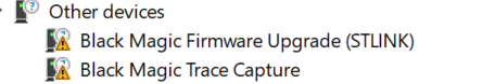
    The 2 new COM ports appear (COM12,COM13), but i cant seem to flash anything successfully.
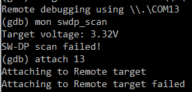
    I've installed the GNU arm toolchain for windows and tried "target extended-remote \.\COM13" (12 just gets stuck on nothing), and i get:
    f2dd9bb6-d333-41a8-b883-b3ba4a97d25f-image.png

    Development

  • GUIDE - NRF5 / NRF51 / NRF52 for beginners
    I idanronen

    Im not sure my flashing with the blackmagic even does anything. The console is unclear:

    Sketch uses 3556 bytes (0%) of program storage space. Maximum is 409600 bytes.
    Remote debugging using \\.\COM11
    Target voltage: ABSENT!
    Available Targets:
    No. Att Driver
     1      Nordic nRF52 M3/M4
     2      Nordic nRF52 Access Port 
    Attaching to Remote target
    0xfffffffe in ?? ()
    Reading symbols from nrf1.ino.elf...done.
    Loading section .text, size 0xde4 lma 0x1c000
    Loading section .ARM.exidx, size 0x8 lma 0x1cde4
    Loading section .data, size 0x78 lma 0x1cdec
    Start address 0x1c578, load size 3684
    Transfer rate: 33 KB/sec, 614 bytes/write.
    Temporary breakpoint 1 at 0x1cb8c: file C:\Users\....\AppData\Local\Arduino15\packages\sandeepmistry\hardware\nRF5\0.6.0\cores\nRF5\main.cpp, line 28.
    Starting program: C:\Users\....\AppData\Local\Temp\arduino_build_366086\nrf1.ino.elf 
    Note: automatically using hardware breakpoints for read-only addresses.
    
    Program received signal SIGSEGV, Segmentation fault.
    0x00000000 in ?? ()
    
    Program complete!
    

    and i dont see any serial debug information

    Development

  • GUIDE - NRF5 / NRF51 / NRF52 for beginners
    I idanronen

    @ncollins I've been working on turning an stm32f030f4p6 into a blackmagic probe for a few days now. Hit a wall when the compiled firmware came out to 83kb which is over the 64kb on board. Found someone who shrunk it down so it'd fit, and someone claiming it has another 64kb which can be unlocked. I'm just looking for the patience to get back in there, as this whole thing has been a major ordeal

    Development

  • GUIDE - NRF5 / NRF51 / NRF52 for beginners
    I idanronen

    @Nca78 no luck with the st-link v2, though i doubt it is related to the board, but rather my inability. i've tried every option in zadig, installed the st-link driver from their website, and nothing works.
    i get this in arduino ide:

    debug_level: 0
    0x4000
    adapter speed: 10000 kHz
    Error: init mode failed (unable to connect to the target)
    in procedure 'program' 
    in procedure 'init' called at file "embedded:startup.tcl", line 473
    in procedure 'ocd_bouncer'
    ** OpenOCD init failed **
    shutdown command invoked
    
    the selected serial port 
     does not exist or your board is not connected
    
    Development

  • GUIDE - NRF5 / NRF51 / NRF52 for beginners
    I idanronen

    @Nca78 I feared that might be the case. my task for today was to dig up my st-link and try that, though I hoped I might have done something wrong and the cp2102 can be used to program and not just debug.
    That module is pretty cheap and from what I see with the naked eye, you can disconnect the cp2102 with the jumpers so the power consumption might actually be good enough to use as-is.
    I'll report back to let you know once I've succeeded

    Development

  • GUIDE - NRF5 / NRF51 / NRF52 for beginners
    I idanronen

    Does anyone know what settings I need to use for this development board with arduino ide?
    Ebyte E104-BT5032A-TB
    https://a.aliexpress.com/_dT5dMb8

    It has a cp2102 on board which I have the driver for. I've installed the arduino ide nrf52 board, but I can't find a programmer, board, or any other settings which will let me flash it without a Java exception or a timeout. Maybe I need to set the jumpers differently but there's no documentation on that.
    OTA works fine though.

    Development

  • What did you build today (Pictures) ?
    I idanronen

    @NeverDie thanks for clarifying!
    So for example in the mini breakout board (https://www.openhardware.io/view/471/Ebyte-nRF52832-Small-Breakout-Board) I could just align the 6 pads and use a standard 6 pin pogo programmer right?

    General Discussion

  • 💬 MySensors Battery Relay
    I idanronen

    Thanks for sharing. How did you get low current while still checking messages frequently enough? Or do you only check for messages every hour or so?

    OpenHardware.io

  • What did you build today (Pictures) ?
    I idanronen

    @NeverDie sorry if it's a bit off topic, but I see that 10 pin ARM box connector you use in several of your designs, and I was wondering if it offers anything extra in addition to the regular 6 pin programming pins. I'm asking specifically because I want to try some of your nrf52832 designs, but would like to avoid spending extra money on special connectors and cables. Thanks!

    General Discussion

  • Multiple radios in 1 gateway
    I idanronen

    @mfalkvidd you're right, there's a lot of 2.4ghz pollution from every device these days, no avoiding that, but specifically having 2 transmitters so close to each other has never been a pleasant experience for me.

    I don't think I've read anything about serial gateway not working on esp8266, it's more the lack of any mention of it anywhere. I mean logically there's no reason why it wouldn't be prevalent, as esp8266 like the D1 Mini costs the same as a nano, is faster with more memory, uses micro usb, no real downside.
    Plus, if you free up the wireless module, you can even use the esp-now protocol instead of connecting a nrf24 (which unfortunately hasn't been implemented in mysensors yet)

    Hardware

  • Multiple radios in 1 gateway
    I idanronen

    @mfalkvidd I see, thanks.
    I guess I'll do esp8266 then, although serial gateway won't work with esp8266 from my understanding, and the wifi gateway will probably interfere with the nrf24

    Hardware

  • Multiple radios in 1 gateway
    I idanronen

    Hi,
    I want to setup a gateway to support multiple radios, in my case nrf24l01 for indoor sensors, and 433mhz Lora for outdoor and far sensors. Would it be possible? What is the limit for number of radios? And what hardware would be best for that esp32 or rpi zero?

    The only other option I see is to set an array of esp32 each with 1 radio.

    Hardware
  • Login

  • Don't have an account? Register

  • Login or register to search.
  • First post
    Last post
0
  • MySensors
  • OpenHardware.io
  • Categories
  • Recent
  • Tags
  • Popular