Navigation

    • Register
    • Login
    • OpenHardware.io
    • Categories
    • Recent
    • Tags
    • Popular
    1. Home
    2. jacikaas
    3. Posts
    • Profile
    • Following
    • Followers
    • Topics
    • Posts
    • Best
    • Groups

    Posts made by jacikaas

    • Sniffing RS485 MODBUS data

      Hello,

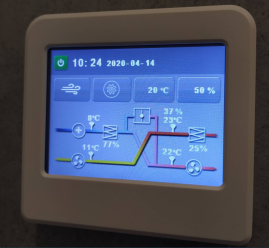
      I have installed ventilation system in my apartment with this LCD acting like separate device:
      6d9528c4-4851-4edc-9976-ca6b2f21bc49-image.png

      It have 4 wires connected. After researching I found main board uses RS485 MODBUS:
      026e8213-51dc-41ec-915d-6939dc497f72-image.png

      I know there is Arduino RS485 modules, which probably could simulate signals to main board. But main problem is I don't know what messages there are. I tried to look for some suggestions on internet, but had no luck. Could some point me how to read this LCD messages to main board so I could simulate same messages over Arduino?

      Thanks!

      posted in Development
      jacikaas
      jacikaas
    • Solenoid water valve

      Hello,

      I tried to search something on this forum, tried to ask in special stores with bathroom supplies, tried to google looks like i found something but nothing what I would like.

      Could someone recommend solenoid water valve for cold and hot water that i could install on my new apartment?

      I would like to have this feature: if water leak sensor is triggered, then it should close solenoid water valves. I found some of these on Aliexpress, but I better choose branded product like Danfoss or simillar.

      Maybe someone is confronted with it and could recommend something?

      Thank You!

      posted in General Discussion
      jacikaas
      jacikaas
    • RE: Curtain Control Node.

      @suresh-mali
      I now reading about that funktions in http://www.airspayce.com/mikem/arduino/AccelStepper/classAccelStepper.html#a344f58fef8cc34ac5aa75ba4b665d21c

      Did what You said, but getting error: no matching function for call to 'AccelStepper::runToPosition(int)'
      I paste here all code, but I think I did everything without mistakes:

      // Enable debug prints to serial monitor
      #define MY_DEBUG
      
      // Enable and select radio type attached
      #define MY_NODE_ID 10
      #define MY_RADIO_NRF24
      //#define MY_RADIO_RFM69
      
      // Enable repeater functionality for this node
      //#define MY_REPEATER_FEATURE
      
      #include <SPI.h>
      #include <MySensors.h>
      #include <AccelStepper.h>
      
      #define HALFSTEP 8
      #define CURTAIN_CLOSED 10000
      #define CURTAIN_OPEN 0
      #define CHILD_ID 1
      
      // int powerPin = 7;
      
      // definicje MySensors
      
      MyMessage message(CHILD_ID, S_COVER);
      
      // Definicja pinow silnika
      #define IN1  3     // IN1
      #define IN2  4     // IN2
      #define IN3  5     // IN3
      #define IN4  6     // IN4
       
      AccelStepper stepper1(HALFSTEP, IN1, IN3, IN2, IN4);
      
      void setup()
      {
        stepper1.setMaxSpeed(1000.0);
        stepper1.setAcceleration(100.0);
        stepper1.setSpeed(200);
        stepper1.runToPosition(CURTAIN_CLOSED);
      }
      
      void presentation() 
      {
        sendSketchInfo("Roller blinds", "1.0");
        present(CHILD_ID, S_COVER); // Window Cover sub-type, commands: V_UP, V_DOWN, V_STOP
      }
      
      void loop()
      {
        //stepper1.run();  //Start
      }
      
      void receive(const MyMessage &message)
      {
      stepper1.enableOutputs ();
        // if message = V_UP start moving until closed
        if (message.type==V_UP) {
           if (stepper1.distanceToGo() == 0){
               if (stepper1.currentPosition() == CURTAIN_OPEN){
                   stepper1.runToPosition(CURTAIN_CLOSED);
           // Store state in eeprom
           saveState(message.sensor, message.getBool());
           request(CHILD_ID, V_UP, 0); // request new values from controller
               }
            }
         }
         if (message.type==V_DOWN) {
             stepper1.moveTo(CURTAIN_OPEN);
             // Store state in eeprom
             saveState(message.sensor, message.getBool());
             request(CHILD_ID, V_DOWN, 0); // request new values from controller   
          }
          if (message.type==V_STOP) {
              stepper1.setCurrentPosition(0);
              // Store state in eeprom
              saveState(message.sensor, message.getBool());
              request(CHILD_ID, V_STOP, 0); // request new values from controller
          }
      stepper1.disableOutputs ();
      }
      
      
      posted in My Project
      jacikaas
      jacikaas
    • RE: Curtain Control Node.

      @suresh-mali Thank You Suresh for Your answer!
      I disconnect relay and delete it lines from the code.

      I add lines to code like You said:

      void receive(const MyMessage &message)
      {
      stepper1.enableOutputs ();
       // rest of code
      stepper1.disableOutputs ();
      }
      

      It looks like it have to work because it is simple solution, but it doesn't... On driver board ULN2003, when motor is not rotating, A Led is always on. I think if command with disableOutputs would be activated, then the LED should not be on?

      posted in My Project
      jacikaas
      jacikaas
    • RE: Curtain Control Node.

      Hello,

      I trying to adopt the code for 28BYJ-48 stepper motor with ULN2003 driver board for roller blinds control. Code is working, but when the stepper motor is always on - it gets hot. Because of it also its consumes more energy. So thats why I want to turn on ULN2003 board only when new action is started, and after that it should be shuted down again. I could do it, because ULN2003 has On/Off jumper:
      alt text

      Question #1: I trying to use relay for that On/Off. Could I do it without relay and control On/Off jumper directly from arduino? Does relay is the best solution?

      Question #2: I suck at programming, but I trying to add theese lines to my code to control the relay SIL05-1A72-71D, which controls the ULN2003 driver board:
      int powerPin = 7; //before SETUP
      pinMode(powerPin, OUTPUT); // In SETUP
      digitalWrite(powerPin, LOW); // In SETUP
      digitalWrite(powerPin, HIGH); // In void receive function
      delay(CURTAIN_CLOSED); // In void receive function
      digitalWrite(powerPin, LOW); // In void receive function

      digitalWrite(powerPin, HIGH); - I think is in right position, but I don't know how to turn off relay when action is done. Please advise for coding, because I not good in it. Thank You! Below is the code:

      // Enable debug prints to serial monitor
      #define MY_DEBUG
      
      // Enable and select radio type attached
      #define MY_NODE_ID 10
      #define MY_RADIO_NRF24
      //#define MY_RADIO_RFM69
      
      // Enable repeater functionality for this node
      //#define MY_REPEATER_FEATURE
      
      #include <SPI.h>
      #include <MySensors.h>
      #include <AccelStepper.h>      //import biblioteki AccelStepper 
      
      #define HALFSTEP 8
      #define CURTAIN_CLOSED 10000  // wartosc gdy kurtyna zamknieta
      #define CURTAIN_OPEN 0       // wartosc gdy kurtyna otwarta
      #define CHILD_ID 1
      
      int powerPin = 7;
      
      // definicje MySensors
      
      MyMessage message(CHILD_ID, S_COVER);
      
      // Definicja pinow silnika
      #define IN1  3     // IN1 - zielony
      #define IN2  4     // IN2 - czarny
      #define IN3  5     // IN3 - niebieski
      #define IN4  6     // IN4 - czerwony
       
      AccelStepper stepper1(HALFSTEP, IN1, IN3, IN2, IN4);
      
      void setup()
      {
        stepper1.setMaxSpeed(1000.0);
        stepper1.setAcceleration(100.0);
        stepper1.setSpeed(200);
        stepper1.moveTo(CURTAIN_OPEN);
        
        pinMode(powerPin, OUTPUT);
        digitalWrite(powerPin, LOW);
      }
      
      void presentation() 
      {
        // Wyslanie informacji o wersji programu
        sendSketchInfo("Roller blinds", "1.0");
        // Register all sensors to gw (they will be created as child devices)
        present(CHILD_ID, S_COVER); // Window Cover sub-type, commands: V_UP, V_DOWN, V_STOP
      }
      
      void loop()
      {
        stepper1.run();  //Start
      }
      
      void receive(const MyMessage &message)
      {
        // if message = V_UP start moving until closed
        if (message.type==V_UP) {
           digitalWrite(powerPin, HIGH);
           if (stepper1.distanceToGo() == 0){
               if (stepper1.currentPosition() == CURTAIN_OPEN){
                   stepper1.moveTo(CURTAIN_CLOSED);
           // Store state in eeprom
           saveState(message.sensor, message.getBool());
           request(CHILD_ID, V_UP, 0); // request new values from controller
               }
            }
         }
         if (message.type==V_DOWN) {
             digitalWrite(powerPin, HIGH);
             stepper1.moveTo(CURTAIN_OPEN);
             // Store state in eeprom
             saveState(message.sensor, message.getBool());
             request(CHILD_ID, V_DOWN, 0); // request new values from controller   
          }
          if (message.type==V_STOP) {
              digitalWrite(powerPin, HIGH);
              stepper1.setCurrentPosition(0);
              // Store state in eeprom
              saveState(message.sensor, message.getBool());
              request(CHILD_ID, V_STOP, 0); // request new values from controller
          }
       //   delay(CURTAIN_CLOSED);
       //   digitalWrite(powerPin, LOW);
      }
      
      
      posted in My Project
      jacikaas
      jacikaas
    • RE: Recommendation for motorized roller blinds solution (actual motor, like somfy, rollertrol, ebay...)

      @nca78
      Yes, thats quite heavy. Need to check it practically. I started to test the motor (now only on the desk), but my 28BYJ-48 motor is shaking with AccelStepper library. With some simple code without included any library - working fine, so I will look why thats happening.

      posted in Hardware
      jacikaas
      jacikaas
    • RE: Recommendation for motorized roller blinds solution (actual motor, like somfy, rollertrol, ebay...)

      @Yveaux
      Yes, that outdoor blinds need a lot more power 🙂

      posted in Hardware
      jacikaas
      jacikaas
    • RE: Recommendation for motorized roller blinds solution (actual motor, like somfy, rollertrol, ebay...)

      Hello. I also thinking of my roller blinds automation and i was found this on thingiverse https://www.thingiverse.com/thing:2392856

      Its very cheap project for 5-10€/window. With 28BYJ-48 stepper motor you at least need 9v psu, it's even better with 12v.

      I also saw, that someone was already discusing in mysensors forum about how to start this motor and there is a code. Of course if you want to use percentage for open blinds, you should modify code and add some typen of encoder on mechanics. https://forum.mysensors.org/topic/3394/curtain-control-node/31

      posted in Hardware
      jacikaas
      jacikaas
    • RE: MYSBootloader 1.3.0-beta.3

      @jacikaas

      Hello, maybe someone was trying 8MHz bootloader for standlaone Atmega328p?

      posted in Development
      jacikaas
      jacikaas
    • RE: MYSBootloader 1.3.0-beta.3

      @tekka thank You for the answer. I'm not sure is answer was dedicated for me or for Mark, but I tested 1.3.0-beta.4 in the same way I described before:

      • Tested with 2 different Atmega328p
      • First try was with 1MHz - working on both Atmega328p
      • Second try with 8MHz - same situation as with beta 3, skecth won't upload and I get answer from Arduino Avrdude (this time I post full log after uploading):
      avrdude: Version 6.3, compiled on Jan 17 2017 at 12:00:53
               Copyright (c) 2000-2005 Brian Dean, http://www.bdmicro.com/
               Copyright (c) 2007-2014 Joerg Wunsch
      
               System wide configuration file is "C:\Program Files (x86)\Arduino\hardware\tools\avr/etc/avrdude.conf"
      
               Using Port                    : COM4
               Using Programmer              : arduino
               Overriding Baud Rate          : 38400
      avrdude: stk500_recv(): programmer is not responding
      avrdude: stk500_getsync() attempt 1 of 10: not in sync: resp=0xf1
      avrdude: stk500_recv(): programmer is not responding
      < ... >
      avrdude: stk500_recv(): programmer is not responding
      avrdude: stk500_getsync() attempt 10 of 10: not in sync: resp=0xf1
      
      avrdude done.  Thank you.
      

      It would be best if someone also could try to burn same bootloader on standalone Atmega328p and post results to be sure all wiring and steps I did is without mistakes.
      Strange if I I burn 1.3pre2 8MHz bootloader - it works.

      What troubleshooting I could make?

      posted in Development
      jacikaas
      jacikaas
    • RE: MYSBootloader 1.3.0-beta.3

      Hello,

      Q1: Does anybody was able to succesfully use 8MHz MYSBootloader 1.3.0-beta.3 on standalone Atmega328p?

      All bootloaders I testing with Arduino BLINK example.
      Arduino 1.8.5

      I was testing 8MHz internal oscilator MYSBootloader 1.3.0-beta.3 with fuses on 2 different Atmega328p standalone but I can't upload sketch to it and test it. Arduino avrdude says that:
      avrdude: stk500_recv(): programmer is not responding
      avrdude: stk500_getsync() attempt 1 of 10: not in sync: resp=0x4a

      Used fuses:
      proMYSBL8.bootloader.low_fuses=0xE2
      proMYSBL8.bootloader.high_fuses=0xDA
      proMYSBL8.bootloader.extended_fuses=0x06 / 07
      proMYSBL8.bootloader.unlock_bits=0x3F
      proMYSBL8.bootloader.lock_bits=0x3F / 0F

      Before that, I was burned my Atmega328p with 1MHz internal oscilator MYSBootloader 1.3.0-beta.3 bootloader and it was working.

      Also I was testing 8MHz internal oscilator MYSBootloader 1.3pre2 with fuses on 2 different Atmega328p standalone and I can upload sketch to it and test it.
      Used fuses:
      proMYSBL8.bootloader.low_fuses=0xE2
      proMYSBL8.bootloader.high_fuses=0xDA
      proMYSBL8.bootloader.extended_fuses=0x06 / 07
      proMYSBL8.bootloader.unlock_bits=0x3F
      proMYSBL8.bootloader.lock_bits=0x3F / 0F

      Q2: I noticed that with 8MHz internal oscilator MYSBootloader 1.3pre2 LED blinks not continuosly it like (* led ON; - led OFF):
      *** --- *** --- *** --- ** - * - * - * - [cycle ends, then repeats again] *** --- *** --- *** --- ** - * - * - * - ...
      And this one cycle of *** --- *** --- *** --- ** - * - * - * - takes ~8 seconds. Could it be something with watchdog timer? I not very know about this setting.

      Thank You for help!

      posted in Development
      jacikaas
      jacikaas
    • RE: MYSBootloader 1.3.0-beta.3

      Hello,

      I have notice strange behavior with MYSBootloaderV13pre.hex 8MHz internal bootloader.

      Problem: When I burn MYSBootloaderV13pre.hex 8MHz internal bootloader to my Standalone Atmega328p i testing it with Arduino Blink and Fade sketches. Problem is that theese sketches doesn't work on this bootloader. LED is just always ON.

      I also tested the same sketches, same wiring, same Arduino Uno (5V when programming), same FTDI programmer (3.3V), same PC with Win 10 with same drivers, same Atmega328p with Nick Gammon Atmega Board Programmer when I burn Lilypad bootloader and then upload Blink and Fade sketches, they perfectly working.

      I tried same uploading with Arduino IDE 1.6.5 and also with the newest version 1.8.5.
      As a programmer I using Arduino as ISP. I theese tests when burning bootloader I don't connect external oscilator.

      With Nick Gammon software I also checked fuses for both Lilypad and MYSBootloader settings, becose i was thought it is becose of them. Once I configure wrong fuses and it had a lot of time to reset it to default value.
      Question: So now before changing fuses I want to ask maybe someone have been faced with similar problem?

      I paste below info about Lilipad and MYSBootloader 8MHz internal oscilator boards fuse settings:

      Lilypad bootloader
      
      Atmega fuse calculator.
      Written by Nick Gammon.
      Version 1.11
      Compiled on Nov 30 2017 at 17:36:58 with Arduino IDE 10805.
      Attempting to enter programming mode ...
      Entered programming mode OK.
      Signature = 0x1E 0x95 0x0F 
      Processor = ATmega328P
      Flash memory size = 32768
      LFuse = 0xE2 
      HFuse = 0xDA 
      EFuse = 0xFD 
      Lock byte = 0xEF 
      Clock calibration = 0x8E 
      External Reset Disable.................. [ ]
      Debug Wire Enable....................... [ ]
      Enable Serial (ICSP) Programming........ [X]
      Watchdog Timer Always On................ [ ]
      Preserve EEPROM through chip erase...... [ ]
      Boot into bootloader.................... [X]
      Divide clock by 8....................... [ ]
      Clock output............................ [ ]
      Bootloader size: 2048 bytes.
      Start-up time: SUT0: [X]  SUT1: [ ] (see datasheet)
      Clock source: calibrated internal oscillator.
      Brownout detection at: 2.7V.
      
      MYSBootloaderV13pre bootloader
      
      Atmega fuse calculator.
      Written by Nick Gammon.
      Version 1.11
      Compiled on Nov 30 2017 at 19:48:16 with Arduino IDE 10805.
      Attempting to enter programming mode ...
      Entered programming mode OK.
      Signature = 0x1E 0x95 0x0F 
      Processor = ATmega328P
      Flash memory size = 32768
      LFuse = 0xE2 
      HFuse = 0xD2 
      EFuse = 0xFE 
      Lock byte = 0xFF 
      Clock calibration = 0x8E 
      External Reset Disable.................. [ ]
      Debug Wire Enable....................... [ ]
      Enable Serial (ICSP) Programming........ [X]
      Watchdog Timer Always On................ [ ]
      Preserve EEPROM through chip erase...... [X]
      Boot into bootloader.................... [X]
      Divide clock by 8....................... [ ]
      Clock output............................ [ ]
      Bootloader size: 2048 bytes.
      Start-up time: SUT0: [X]  SUT1: [ ] (see datasheet)
      Clock source: calibrated internal oscillator.
      Brownout detection at: 1.8V.
      

      I appreciate any helpful info!

      EDIT: I think I already found that there is newer MYSBootloader files of development version which working without problems. I will test it if I write good fuses 🙂

      posted in Development
      jacikaas
      jacikaas
    • RE: mysgw: bind: Address already in use

      @mfalkvidd

      Thank You for the answer.

      @mfalkvidd said in mysgw: bind: Address already in use:

      As mentioned in the troubleshooting section, look in /var/log/syslog to see the gateway output of the existing instance. Don't start a new one.

      Ohh... Thats a lot more clear now... I thought command "sudo ./bin/mysgw -d" is not a service start, but just something like output mirror. Like "tail". Could I somehow use tail for watching real time output on ./bin/mysgw -d ?

      Also, it seems your sudo key has gotten stuck 😞 If you missed that not every command is preceeded by sudo in the build instructions, maybe it is worth considering that you missed something else?

      Sorry for dumb questions, but how I make that sudo key stuck? It's becose of that I start a few mysgw services?

      Another silly question, becose I'm very "advanced user" in UNIX, my best friend is called desktop there, and I know basically just install, nano, cp, rm commands, I need to ask 🙂 Is there should be difference if I will use "make" instead of "sudo make". Sudo means that I run this command by root user, but does it make difference between "make" or "sudo make"? And if I remember clearly if I run only "make" - raspberry pi starts to swearing, but with sudo, it's ok.

      When I install the gateway by command "sudo make install" I can see that installing was successful, there is info that if I want to run this on boot I need to run two lines:

      • sudo systemctl enable mysgw.service
      • sudo systemctl start mysgw.service

      But now, I guess, I do not need them both, because start on boot is described in "sudo make install"?

      posted in Troubleshooting
      jacikaas
      jacikaas
    • RE: mysgw: bind: Address already in use

      Hello,
      I asking for help with same question. How I see there is no solution, so I try to explain step by step what I did and whats the problem I have.

      1. I install Domoticz on fresh Raspberry Pi Raspbian image

      2. Build a Raspberry Pi Ethernet Gateway by instructions (https://www.mysensors.org/build/raspberry)

        • git clone https://github.com/mysensors/MySensors.git --branch master
        • cd MySensors
        • sudo ./configure --my-transport=nrf24 --my-gateway=ethernet --my-port=5003
      3. After that comand I have answer, that my SoC and Type of machine unknown (I using RPi 2):

      [SECTION] Detecting target machine.
        [OK] machine detected: SoC=unknown, Type=unknown, CPU=armv7l.
      

      But I found the solution about that in forum, where I change two lines of the configure file to "BCM2835":

      function detect_machine {
      ...
          case $hardware in
      ...
          BCM2835)
              soc="BCM2835"
              if [[ $machine == "Raspberry"* ]]; then
                  local rev=($(detect_rpi_revision))
                  if [[ $rev == "a02082" || $rev == "a22082" ]]; then
                      tp="RPi3"
                  else
                      tp="Rpi2"
                  fi
              fi
              ;;
      ...
      

      After changing it , all looks fine.

      1. I repeat
        • sudo ./configure --my-transport=nrf24 --my-gateway=ethernet --my-port=5003

      My board is recognized so I continue with gateway building instructions...

      • sudo make
      • sudo ./bin/mysgw -h
      • sudo ./bin/mysgw -d

      And I got results with no errors, gateway is running. Continue with comands

      • sudo make install
      • sudo systemctl enable mysgw.service
      • sudo systemctl start mysgw.service

      No errors. I connect one LED strip node to Domoticz and its working perfectly.
      But after ~10 minutes trying to on/off LED strip it doesn't work anymore. Nothing was changed. Checking the gateway with command:

      • sudo ./bin/mysgw -d

      And getting:

      Sep 24 21:37:15 raspberrypi mysgw: accept: Bad file descriptor
      Sep 24 21:37:15 raspberrypi mysgw: accept: Bad file descriptor
      Sep 24 21:37:15 raspberrypi mysgw: accept: Bad file descriptor
      Sep 24 21:37:15 raspberrypi mysgw: accept: Bad file descriptor
      Sep 24 21:37:15 raspberrypi mysgw: accept: Bad file descriptor
      Sep 24 21:37:15 raspberrypi mysgw: accept: Bad file descriptor
      

      Output of "ps -ax" command:

        PID TTY      STAT   TIME COMMAND
          1 ?        Ss     0:02 /sbin/init splash
          2 ?        S      0:00 [kthreadd]
          3 ?        S      0:00 [ksoftirqd/0]
          5 ?        S<     0:00 [kworker/0:0H]
          6 ?        S      0:00 [kworker/u8:0]
          7 ?        S      0:01 [rcu_sched]
          8 ?        S      0:00 [rcu_bh]
          9 ?        S      0:00 [migration/0]
         10 ?        S<     0:00 [lru-add-drain]
         11 ?        S      0:00 [cpuhp/0]
         12 ?        S      0:00 [cpuhp/1]
         13 ?        S      0:00 [migration/1]
         14 ?        S      0:00 [ksoftirqd/1]
         16 ?        S<     0:00 [kworker/1:0H]
         17 ?        S      0:00 [cpuhp/2]
         18 ?        S      0:00 [migration/2]
         19 ?        S      0:00 [ksoftirqd/2]
         21 ?        S<     0:00 [kworker/2:0H]
         22 ?        S      0:00 [cpuhp/3]
         23 ?        S      0:00 [migration/3]
         24 ?        S      0:00 [ksoftirqd/3]
         26 ?        S<     0:00 [kworker/3:0H]
         27 ?        S      0:00 [kdevtmpfs]
         28 ?        S<     0:00 [netns]
         29 ?        S      0:00 [khungtaskd]
         30 ?        S      0:00 [oom_reaper]
         31 ?        S<     0:00 [writeback]
         32 ?        S      0:00 [kcompactd0]
         33 ?        S<     0:00 [crypto]
         34 ?        S<     0:00 [bioset]
         35 ?        S<     0:00 [kblockd]
         36 ?        S<     0:00 [watchdogd]
         37 ?        S      0:00 [kworker/0:1]
         38 ?        S<     0:00 [rpciod]
         39 ?        S<     0:00 [xprtiod]
         40 ?        S      0:00 [kswapd0]
         41 ?        S<     0:00 [vmstat]
         42 ?        S<     0:00 [nfsiod]
         52 ?        S<     0:00 [kthrotld]
         53 ?        S<     0:00 [bioset]
         54 ?        S<     0:00 [bioset]
         55 ?        S<     0:00 [bioset]
         56 ?        S<     0:00 [bioset]
         57 ?        S<     0:00 [bioset]
         58 ?        S<     0:00 [bioset]
         59 ?        S<     0:00 [bioset]
         60 ?        S<     0:00 [bioset]
         61 ?        S<     0:00 [bioset]
         62 ?        S<     0:00 [bioset]
         63 ?        S<     0:00 [bioset]
         64 ?        S<     0:00 [bioset]
         65 ?        S<     0:00 [bioset]
         66 ?        S<     0:00 [bioset]
         67 ?        S<     0:00 [bioset]
         68 ?        S<     0:00 [bioset]
         69 ?        S<     0:00 [bioset]
         70 ?        S<     0:00 [bioset]
         71 ?        S<     0:00 [bioset]
         72 ?        S<     0:00 [bioset]
         73 ?        S<     0:00 [bioset]
         74 ?        S<     0:00 [bioset]
         75 ?        S<     0:00 [bioset]
         76 ?        S<     0:00 [bioset]
         77 ?        S<     0:00 [iscsi_eh]
         78 ?        S<     0:00 [dwc_otg]
         80 ?        S<     0:00 [DWC Notificatio]
         81 ?        S<     0:00 [VCHIQ-0]
         82 ?        S<     0:00 [VCHIQr-0]
         83 ?        S<     0:00 [VCHIQs-0]
         84 ?        S      0:00 [VCHIQka-0]
         85 ?        S<     0:00 [SMIO]
         88 ?        S<     0:00 [bioset]
         89 ?        S      0:00 [mmcqd/0]
         90 ?        S      0:00 [jbd2/mmcblk0p2-]
         91 ?        S<     0:00 [ext4-rsv-conver]
         93 ?        S      0:00 [kworker/3:1]
         94 ?        S<     0:00 [ipv6_addrconf]
        109 ?        S<     0:00 [kworker/1:1H]
        110 ?        S      0:00 [kworker/u8:1]
        115 ?        Ss     0:11 /lib/systemd/systemd-journald
        144 ?        S      0:00 [kworker/1:3]
        150 ?        Ss     0:00 /lib/systemd/systemd-udevd
        200 ?        S      0:00 [spi0]
        238 ?        S      0:00 [kworker/3:2]
        266 ?        Ssl    0:00 /lib/systemd/systemd-timesyncd
        288 ?        Ss     0:00 /usr/bin/dbus-daemon --system --address=systemd: --nofork --nopidfile --systemd-activation
        291 ?        Ss     0:00 /usr/sbin/cron -f
        292 ?        Ssl    0:04 /usr/sbin/rsyslogd -n
        293 ?        Ss     0:00 avahi-daemon: running [raspberrypi.local]
        295 ?        Rs    80:53 /usr/local/bin/mysgw
        297 ?        Ss     0:00 /lib/systemd/systemd-logind
        299 ?        Ss     0:00 /usr/sbin/thd --triggers /etc/triggerhappy/triggers.d/ --socket /run/thd.socket --user nobody --deviceglob /dev/input/event*
        309 ?        S      0:00 avahi-daemon: chroot helper
        320 ?        S<     0:00 [cfg80211]
        324 ?        Ss     0:00 /sbin/dhcpcd -q -b
        359 ?        Ss     0:00 /usr/sbin/sshd -D
        378 ?        Ssl    0:00 /usr/sbin/lightdm
        381 ?        S<     0:00 [kworker/2:1H]
        390 tty1     Ss     0:00 /bin/login -f
        393 ?        Ss+    0:00 /sbin/agetty --keep-baud 115200,38400,9600 ttyAMA0 vt220
        400 tty7     Ssl+   0:03 /usr/lib/xorg/Xorg :0 -seat seat0 -auth /var/run/lightdm/root/:0 -nolisten tcp vt7 -novtswitch
        402 ?        Ssl    0:16 /home/pi/domoticz/domoticz -daemon -www 8080 -sslwww 443
        403 ?        S<     0:00 [kworker/3:1H]
        431 ?        Sl     0:00 lightdm --session-child 14 17
        439 ?        Ss     0:00 /lib/systemd/systemd --user
        442 ?        S      0:00 (sd-pam)
        447 ?        Ssl    0:00 /usr/bin/lxsession -s LXDE-pi -e LXDE
        456 ?        Ss     0:00 /usr/bin/dbus-daemon --session --address=systemd: --nofork --nopidfile --systemd-activation
        501 tty1     S+     0:00 -bash
        520 ?        Ss     0:00 /usr/bin/ssh-agent x-session-manager
        526 ?        Ssl    0:00 /usr/lib/gvfs/gvfsd
        531 ?        Sl     0:00 /usr/lib/gvfs/gvfsd-fuse /run/user/1000/gvfs -f -o big_writes
        547 ?        S      0:01 openbox --config-file /home/pi/.config/openbox/lxde-pi-rc.xml
        549 ?        Sl     0:00 lxpolkit
        551 ?        Sl     0:12 lxpanel --profile LXDE-pi
        553 ?        Sl     0:01 pcmanfm --desktop --profile LXDE-pi
        561 ?        Ss     0:00 /usr/bin/ssh-agent -s
        570 ?        Ssl    0:00 /usr/lib/policykit-1/polkitd --no-debug
        585 ?        Ssl    0:00 /usr/lib/menu-cache/menu-cached /run/user/1000/menu-cached-:0
        589 ?        Ssl    0:00 /usr/lib/gvfs/gvfs-udisks2-volume-monitor
        592 ?        Ssl    0:00 /usr/lib/udisks2/udisksd --no-debug
        603 ?        Ssl    0:00 /usr/lib/gvfs/gvfs-goa-volume-monitor
        607 ?        Ssl    0:00 /usr/lib/gvfs/gvfs-mtp-volume-monitor
        611 ?        Ssl    0:00 /usr/lib/gvfs/gvfs-gphoto2-volume-monitor
        620 ?        Ssl    0:00 /usr/lib/gvfs/gvfs-afc-volume-monitor
        633 ?        Sl     0:00 /usr/lib/gvfs/gvfsd-trash --spawner :1.4 /org/gtk/gvfs/exec_spaw/0
        733 ?        S      0:00 sudo ./bin/mysgw -d
        737 ?        R     80:45 ./bin/mysgw -d
        751 ?        S<     0:00 [kworker/0:1H]
        760 ?        S      0:00 [kworker/0:0]
        761 ?        S      0:00 [kworker/1:1]
        766 ?        Ss     0:00 sshd: pi [priv]
        776 ?        R      0:01 sshd: pi@pts/1
        779 pts/1    Ss     0:00 -bash
        805 pts/1    T      0:00 sudo ./bin/mysgw -d
        809 pts/1    T      0:25 ./bin/mysgw -d
        850 ?        S      0:00 [kworker/2:1]
        857 ?        S      0:00 [kworker/2:0]
        862 pts/1    R+     0:00 ps -ax
      

      cat /sys/firmware/devicetree/base/model

      Raspberry Pi 2 Model B Rev 1.1
      

      Don't know how to fix that
      Sep 24 21:37:15 raspberrypi mysgw: accept: Bad file descriptor

      Looks like I using gateway building instructions step by step, but something is missing... Thanks.

      posted in Troubleshooting
      jacikaas
      jacikaas
    • RE: 💬 Building a Raspberry Pi Gateway

      @ccy

      Hello, I'm also have issue with this question. My Raspberry Pi 2 type is a01041, but by the original "configure" file it is not recognized:

      [SECTION] Detecting target machine.
        [OK] machine detected: SoC=unknown, Type=unknown, CPU=armv7l.
      

      Maybe someone could explain why it is not recognized?

      "Configure" file lines:

      function detect_machine {
      ...
          case $hardware in
      ...
          BCM2835)
              soc="BCM2835"
              if [[ $machine == "Raspberry"* ]]; then
                  local rev=($(detect_rpi_revision))
                  if [[ $rev == "a02082" || $rev == "a22082" ]]; then
                      tp="RPi3"
                  else
                      tp="Rpi2"
                  fi
              fi
              ;;
      ...
      
      My Raspberry Pi 2 info:
      processor       : 0
      model name      : ARMv7 Processor rev 5 (v7l)
      BogoMIPS        : 38.40
      Features        : half thumb fastmult vfp edsp neon vfpv3 tls vfpv4 idiva idivt vfpd32 lpae evtstrm
      CPU implementer : 0x41
      CPU architecture: 7
      CPU variant     : 0x0
      CPU part        : 0xc07
      CPU revision    : 5
      
      processor       : 1
      model name      : ARMv7 Processor rev 5 (v7l)
      BogoMIPS        : 38.40
      Features        : half thumb fastmult vfp edsp neon vfpv3 tls vfpv4 idiva idivt vfpd32 lpae evtstrm
      CPU implementer : 0x41
      CPU architecture: 7
      CPU variant     : 0x0
      CPU part        : 0xc07
      CPU revision    : 5
      
      processor       : 2
      model name      : ARMv7 Processor rev 5 (v7l)
      BogoMIPS        : 38.40
      Features        : half thumb fastmult vfp edsp neon vfpv3 tls vfpv4 idiva idivt vfpd32 lpae evtstrm
      CPU implementer : 0x41
      CPU architecture: 7
      CPU variant     : 0x0
      CPU part        : 0xc07
      CPU revision    : 5
      
      processor       : 3
      model name      : ARMv7 Processor rev 5 (v7l)
      BogoMIPS        : 38.40
      Features        : half thumb fastmult vfp edsp neon vfpv3 tls vfpv4 idiva idivt vfpd32 lpae evtstrm
      CPU implementer : 0x41
      CPU architecture: 7
      CPU variant     : 0x0
      CPU part        : 0xc07
      CPU revision    : 5
      
      Hardware        : BCM2835
      Revision        : a01041
      Serial          : 0000000049a14619
      posted in Announcements
      jacikaas
      jacikaas
    • Different Node ID for same node

      Hello,

      Does Node ID which I set on the node when I'm uploading code need to be same when it shows in Domoticz?

      MyController:
      0_1491041637857_upload-da348eef-39b4-462e-bd94-14723da9f607

      Domoticz LOG:

      2017-04-01 13:00:35.251 MySensors: Node: 21, Sketch Name: Plant moisture w bat
      2017-04-01 13:00:35.252 MySensors: Node: 21, Sketch Version: 1.5
      2017-04-01 13:00:36.253 (NRF RPi) Humidity (Hum)
      2017-04-01 13:00:36.256 (NRF RPi) General/Voltage (Voltage)
      

      Domoticz ID column:
      0_1491041818469_upload-9a546f39-4aa9-43d5-a6e6-691f37f3cb52

      posted in Domoticz
      jacikaas
      jacikaas
    • RE: MYSBootloader 1.3.0-beta.3

      Hi,

      Is there going to be 1 and 8MHz MySBootloader hex files? 🙂

      Thanks!

      posted in Development
      jacikaas
      jacikaas
    • RE: 💬 Building a Raspberry Pi Gateway

      Hello,

      Could someone answer: if i have RPi NRF24 GW, how I could connect MYSController from other computer (for example from Windows computer)?

      1. Is it possible to make that type connection with RPi NRF24 GW?
      2. May I use some integrated web server for this type of connection in RPi to make it work? Is there are easier solutions?

      EDIT: no matter, already answered it by myself 🙂
      Its easy becose it's like Ethernet GW.

      posted in Announcements
      jacikaas
      jacikaas
    • RE: Converting to 2.0 Slim Node as a Mini 2AA Battery PIR Motion Sensor code

      @Martin-Tellblom

      Hey, try like that:
      https://goo.gl/images/pQ9nTU

      posted in Troubleshooting
      jacikaas
      jacikaas
    • RE: ENC28J60 Ethernet gateway problem with Domoticz?

      Maybe someone have minds on my recent post here?

      posted in Troubleshooting
      jacikaas
      jacikaas
    • RE: ENC28J60 Ethernet gateway problem with Domoticz?

      Hello,

      I already post my problem on MYSBootloader 1.3pre2 testing theme, but I'm not sure does my issue is on right topic.

      I wondering where should I post this message.

      Problem: I can't connect to my GW with MYSController 1.0.0beta (build 3315). In MYSC log I get: "Error on connect: connection refused"
      Screenshot:
      0_1481056405084_2016-12-05_2306.png

      My GW software is ENC28J60 Ethernet module. I check GW LOG and how I understand there is no special info (beside 2 messages for relay on and off) which could help me:

      0;255;3;0;9;Starting gateway (RNNGA-, 2.0.0)
      0;255;3;0;9;TSM:INIT
      0;255;3;0;9;TSM:RADIO:OK
      0;255;3;0;9;TSM:GW MODE
      0;255;3;0;9;TSM:READY
      IP: 192.168.1.3
      0;255;3;0;9;No registration required
      0;255;3;0;9;Init complete, id=0, parent=0, distance=0, registration=1
      0;255;3;0;9;Eth: connect
      0;255;3;0;9;Eth: 0;0;3;0;2;
      0;255;3;0;9;Eth: 0;0;3;0;2;Get Version
      0;255;3;0;9;Eth: 0;0;3;0;18;PING
      0;255;3;0;9;Eth: 0;0;3;0;18;PING
      0;255;3;0;9;Eth: 0;0;3;0;18;PING
      0;255;3;0;9;TSP:SANCHK:OK
      0;255;3;0;9;Eth: 0;0;3;0;18;PING
      0;255;3;0;9;Eth: 0;0;3;0;18;PING
      0;255;3;0;9;Eth: 0;0;3;0;18;PING
      0;255;3;0;9;Eth: 0;0;3;0;18;PING
      0;255;3;0;9;Eth: 0;0;3;0;18;PING
      0;255;3;0;9;Eth: 0;0;3;0;18;PING
      0;255;3;0;9;TSP:SANCHK:OK
      0;255;3;0;9;Eth: 0;0;3;0;18;PING
      0;255;3;0;9;Eth: 0;0;3;0;18;PING
      0;255;3;0;9;Eth: 0;0;3;0;18;PING
      0;255;3;0;9;Eth: 0;0;3;0;18;PING
      0;255;3;0;9;Eth: 0;0;3;0;18;PING
      0;255;3;0;9;Eth: 0;0;3;0;18;PING
      0;255;3;0;9;TSP:SANCHK:OK
      0;255;3;0;9;Eth: 0;0;3;0;18;PING
      0;255;3;0;9;Eth: 0;0;3;0;18;PING
      0;255;3;0;9;Eth: 0;0;3;0;18;PING
      0;255;3;0;9;Eth: 0;0;3;0;18;PING
      0;255;3;0;9;Eth: 0;0;3;0;18;PING
      0;255;3;0;9;Eth: 0;0;3;0;18;PING
      0;255;3;0;9;TSP:SANCHK:OK
      0;255;3;0;9;Eth: 0;0;3;0;18;PING
      0;255;3;0;9;Eth: 0;0;3;0;18;PING
      0;255;3;0;9;Eth: 0;0;3;0;18;PING
      0;255;3;0;9;Eth: 0;0;3;0;18;PING
      0;255;3;0;9;Eth: 0;0;3;0;18;PING
      0;255;3;0;9;Eth: 6;9;1;1;2;1
      0;255;3;0;9;TSP:MSG:SEND 0-0-4-6 s=9,c=1,t=2,pt=0,l=1,sg=0,ft=0,st=ok:1
      0;255;3;0;9;TSP:MSG:READ 6-4-0 s=9,c=1,t=2,pt=0,l=1,sg=0:1
      0;255;3;0;9;TSP:MSG:READ 6-4-0 s=9,c=1,t=3,pt=1,l=1,sg=0:100
      0;255;3;0;9;Eth: 6;9;1;1;2;0
      0;255;3;0;9;TSP:MSG:SEND 0-0-4-6 s=9,c=1,t=2,pt=0,l=1,sg=0,ft=0,st=ok:0
      0;255;3;0;9;TSP:MSG:READ 6-4-0 s=9,c=1,t=2,pt=0,l=1,sg=0:0
      0;255;3;0;9;TSP:MSG:READ 6-4-0 s=9,c=1,t=3,pt=1,l=1,sg=0:0
      0;255;3;0;9;Eth: 0;0;3;0;18;PING
      0;255;3;0;9;TSP:SANCHK:OK
      0;255;3;0;9;Eth: 0;0;3;0;18;PING
      0;255;3;0;9;Eth: 0;0;3;0;18;PING
      0;255;3;0;9;Eth: 0;0;3;0;18;PING
      0;255;3;0;9;Eth: 0;0;3;0;18;PING
      0;255;3;0;9;Eth: 0;0;3;0;18;PING
      0;255;3;0;9;Eth: 0;0;3;0;18;PING
      0;255;3;0;9;TSP:SANCHK:OK
      0;255;3;0;9;Eth: 0;0;3;0;18;PING
      

      I'm using 2.0.0 MySensors library.
      My GW is Arduino Pro Mini + ENC28J60 Ethernet module + NRF24L01+
      My Arduino software: 1.6.11 (Windows)
      I have few nodes in NRF24 network, and all of them are on 2.0.0 library.

      One thing that could be related with this issue that I getting an error becose of library when I upload my code to Arduino ENC28J60 Ethernet module. I tried install again that library few times, but got the same error. Library UIPEthernet is from (MySensors GitHub Uploaded librarys). Error code which I get when uploading:

      In file included from C:\Users\Moni\Documents\Arduino\libraries\UIPEthernet/UIPEthernet.h:33:0,
      
                       from C:\Users\Moni\Google Drive\Smart Home\Sketches\GatewayENC28J60__modifikuotas\GatewayENC28J60__modifikuotas.ino:92:
      
      C:\Users\Moni\Documents\Arduino\libraries\UIPEthernet/UIPClient.h:25:2: warning: #import is a deprecated GCC extension [-Wdeprecated]
      
       #import "Client.h"
      
        ^
      
      In file included from C:\Users\Moni\Documents\Arduino\libraries\UIPEthernet/UIPEthernet.h:33:0,
      
                       from C:\Users\Moni\Google Drive\Smart Home\Sketches\GatewayENC28J60__modifikuotas\GatewayENC28J60__modifikuotas.ino:92:
      
      C:\Users\Moni\Documents\Arduino\libraries\UIPEthernet/UIPClient.h:26:2: warning: #import is a deprecated GCC extension [-Wdeprecated]
      
       #import "utility/mempool.h"
      
        ^
      
      C:\Users\Moni\Documents\Arduino\libraries\UIPEthernet/UIPClient.h:29:4: warning: #import is a deprecated GCC extension [-Wdeprecated]
      
         #import "utility/uip.h"
      
          ^
      
      In file included from C:\Users\Moni\Documents\Arduino\libraries\UIPEthernet/UIPEthernet.h:34:0,
      
                       from C:\Users\Moni\Google Drive\Smart Home\Sketches\GatewayENC28J60__modifikuotas\GatewayENC28J60__modifikuotas.ino:92:
      
      C:\Users\Moni\Documents\Arduino\libraries\UIPEthernet/UIPServer.h:23:2: warning: #import is a deprecated GCC extension [-Wdeprecated]
      
       #import "Server.h"
      
        ^
      
      In file included from C:\Users\Moni\Documents\Arduino\libraries\UIPEthernet/UIPEthernet.h:34:0,
      
                       from C:\Users\Moni\Google Drive\Smart Home\Sketches\GatewayENC28J60__modifikuotas\GatewayENC28J60__modifikuotas.ino:92:
      
      C:\Users\Moni\Documents\Arduino\libraries\UIPEthernet/UIPServer.h:24:2: warning: #import is a deprecated GCC extension [-Wdeprecated]
      
       #import "UIPClient.h"
      
        ^
      
      In file included from C:\Users\Moni\Documents\Arduino\libraries\UIPEthernet\Dhcp.cpp:8:0:
      
      C:\Users\Moni\Documents\Arduino\libraries\UIPEthernet\utility/util.h:5:0: warning: "ntohs" redefined
      
       #define ntohs(x) htons(x)
      
       ^
      
      In file included from C:\Users\Moni\Documents\Arduino\libraries\UIPEthernet\UIPUdp.h:28:0,
      
                       from C:\Users\Moni\Documents\Arduino\libraries\UIPEthernet\Dhcp.h:7,
      
                       from C:\Users\Moni\Documents\Arduino\libraries\UIPEthernet\Dhcp.cpp:6:
      
      C:\Users\Moni\Documents\Arduino\libraries\UIPEthernet\utility/uip.h:1087:0: note: this is the location of the previous definition
      
       #define ntohs htons
      
       ^
      
      C:\Users\Moni\Documents\Arduino\libraries\UIPEthernet\UIPClient.cpp:22:2: warning: #import is a deprecated GCC extension [-Wdeprecated]
      
       #import "utility/uip-conf.h"
      
        ^
      
      C:\Users\Moni\Documents\Arduino\libraries\UIPEthernet\UIPClient.cpp:23:2: warning: #import is a deprecated GCC extension [-Wdeprecated]
      
       #import "utility/uip.h"
      
        ^
      
      C:\Users\Moni\Documents\Arduino\libraries\UIPEthernet\UIPClient.cpp:24:2: warning: #import is a deprecated GCC extension [-Wdeprecated]
      
       #import "utility/uip_arp.h"
      
        ^
      
      C:\Users\Moni\Documents\Arduino\libraries\UIPEthernet\UIPClient.cpp:25:2: warning: #import is a deprecated GCC extension [-Wdeprecated]
      
       #import "string.h"
      
        ^
      
      In file included from C:\Users\Moni\Documents\Arduino\libraries\UIPEthernet\UIPEthernet.h:33:0,
      
                       from C:\Users\Moni\Documents\Arduino\libraries\UIPEthernet\UIPClient.cpp:27:
      
      C:\Users\Moni\Documents\Arduino\libraries\UIPEthernet\UIPClient.h:25:2: warning: #import is a deprecated GCC extension [-Wdeprecated]
      
       #import "Client.h"
      
        ^
      
      In file included from C:\Users\Moni\Documents\Arduino\libraries\UIPEthernet\UIPEthernet.h:33:0,
      
                       from C:\Users\Moni\Documents\Arduino\libraries\UIPEthernet\UIPClient.cpp:27:
      
      C:\Users\Moni\Documents\Arduino\libraries\UIPEthernet\UIPClient.h:26:2: warning: #import is a deprecated GCC extension [-Wdeprecated]
      
       #import "utility/mempool.h"
      
        ^
      
      C:\Users\Moni\Documents\Arduino\libraries\UIPEthernet\UIPClient.h:29:4: warning: #import is a deprecated GCC extension [-Wdeprecated]
      
         #import "utility/uip.h"
      
          ^
      
      In file included from C:\Users\Moni\Documents\Arduino\libraries\UIPEthernet\UIPEthernet.h:34:0,
      
                       from C:\Users\Moni\Documents\Arduino\libraries\UIPEthernet\UIPClient.cpp:27:
      
      C:\Users\Moni\Documents\Arduino\libraries\UIPEthernet\UIPServer.h:23:2: warning: #import is a deprecated GCC extension [-Wdeprecated]
      
       #import "Server.h"
      
        ^
      
      In file included from C:\Users\Moni\Documents\Arduino\libraries\UIPEthernet\UIPEthernet.h:34:0,
      
                       from C:\Users\Moni\Documents\Arduino\libraries\UIPEthernet\UIPClient.cpp:27:
      
      C:\Users\Moni\Documents\Arduino\libraries\UIPEthernet\UIPServer.h:24:2: warning: #import is a deprecated GCC extension [-Wdeprecated]
      
       #import "UIPClient.h"
      
        ^
      
      In file included from C:\Users\Moni\Documents\Arduino\libraries\UIPEthernet\UIPEthernet.h:33:0,
      
                       from C:\Users\Moni\Documents\Arduino\libraries\UIPEthernet\UIPEthernet.cpp:21:
      
      C:\Users\Moni\Documents\Arduino\libraries\UIPEthernet\UIPClient.h:25:2: warning: #import is a deprecated GCC extension [-Wdeprecated]
      
       #import "Client.h"
      
        ^
      
      In file included from C:\Users\Moni\Documents\Arduino\libraries\UIPEthernet\UIPEthernet.h:33:0,
      
                       from C:\Users\Moni\Documents\Arduino\libraries\UIPEthernet\UIPEthernet.cpp:21:
      
      C:\Users\Moni\Documents\Arduino\libraries\UIPEthernet\UIPClient.h:26:2: warning: #import is a deprecated GCC extension [-Wdeprecated]
      
       #import "utility/mempool.h"
      
        ^
      
      C:\Users\Moni\Documents\Arduino\libraries\UIPEthernet\UIPClient.h:29:4: warning: #import is a deprecated GCC extension [-Wdeprecated]
      
         #import "utility/uip.h"
      
          ^
      
      In file included from C:\Users\Moni\Documents\Arduino\libraries\UIPEthernet\UIPEthernet.h:34:0,
      
                       from C:\Users\Moni\Documents\Arduino\libraries\UIPEthernet\UIPEthernet.cpp:21:
      
      C:\Users\Moni\Documents\Arduino\libraries\UIPEthernet\UIPServer.h:23:2: warning: #import is a deprecated GCC extension [-Wdeprecated]
      
       #import "Server.h"
      
        ^
      
      In file included from C:\Users\Moni\Documents\Arduino\libraries\UIPEthernet\UIPEthernet.h:34:0,
      
                       from C:\Users\Moni\Documents\Arduino\libraries\UIPEthernet\UIPEthernet.cpp:21:
      
      C:\Users\Moni\Documents\Arduino\libraries\UIPEthernet\UIPServer.h:24:2: warning: #import is a deprecated GCC extension [-Wdeprecated]
      
       #import "UIPClient.h"
      
        ^
      
      In file included from C:\Users\Moni\Documents\Arduino\libraries\UIPEthernet\UIPEthernet.h:33:0,
      
                       from C:\Users\Moni\Documents\Arduino\libraries\UIPEthernet\UIPServer.cpp:19:
      
      C:\Users\Moni\Documents\Arduino\libraries\UIPEthernet\UIPClient.h:25:2: warning: #import is a deprecated GCC extension [-Wdeprecated]
      
       #import "Client.h"
      
        ^
      
      In file included from C:\Users\Moni\Documents\Arduino\libraries\UIPEthernet\UIPEthernet.h:33:0,
      
                       from C:\Users\Moni\Documents\Arduino\libraries\UIPEthernet\UIPServer.cpp:19:
      
      C:\Users\Moni\Documents\Arduino\libraries\UIPEthernet\UIPClient.h:26:2: warning: #import is a deprecated GCC extension [-Wdeprecated]
      
       #import "utility/mempool.h"
      
        ^
      
      C:\Users\Moni\Documents\Arduino\libraries\UIPEthernet\UIPClient.h:29:4: warning: #import is a deprecated GCC extension [-Wdeprecated]
      
         #import "utility/uip.h"
      
          ^
      
      In file included from C:\Users\Moni\Documents\Arduino\libraries\UIPEthernet\UIPEthernet.h:34:0,
      
                       from C:\Users\Moni\Documents\Arduino\libraries\UIPEthernet\UIPServer.cpp:19:
      
      C:\Users\Moni\Documents\Arduino\libraries\UIPEthernet\UIPServer.h:23:2: warning: #import is a deprecated GCC extension [-Wdeprecated]
      
       #import "Server.h"
      
        ^
      
      In file included from C:\Users\Moni\Documents\Arduino\libraries\UIPEthernet\UIPEthernet.h:34:0,
      
                       from C:\Users\Moni\Documents\Arduino\libraries\UIPEthernet\UIPServer.cpp:19:
      
      C:\Users\Moni\Documents\Arduino\libraries\UIPEthernet\UIPServer.h:24:2: warning: #import is a deprecated GCC extension [-Wdeprecated]
      
       #import "UIPClient.h"
      
        ^
      
      In file included from C:\Users\Moni\Documents\Arduino\libraries\UIPEthernet\UIPEthernet.h:33:0,
      
                       from C:\Users\Moni\Documents\Arduino\libraries\UIPEthernet\UIPUdp.cpp:20:
      
      C:\Users\Moni\Documents\Arduino\libraries\UIPEthernet\UIPClient.h:25:2: warning: #import is a deprecated GCC extension [-Wdeprecated]
      
       #import "Client.h"
      
        ^
      
      In file included from C:\Users\Moni\Documents\Arduino\libraries\UIPEthernet\UIPEthernet.h:33:0,
      
                       from C:\Users\Moni\Documents\Arduino\libraries\UIPEthernet\UIPUdp.cpp:20:
      
      C:\Users\Moni\Documents\Arduino\libraries\UIPEthernet\UIPClient.h:26:2: warning: #import is a deprecated GCC extension [-Wdeprecated]
      
       #import "utility/mempool.h"
      
        ^
      
      C:\Users\Moni\Documents\Arduino\libraries\UIPEthernet\UIPClient.h:29:4: warning: #import is a deprecated GCC extension [-Wdeprecated]
      
         #import "utility/uip.h"
      
          ^
      
      In file included from C:\Users\Moni\Documents\Arduino\libraries\UIPEthernet\UIPEthernet.h:34:0,
      
                       from C:\Users\Moni\Documents\Arduino\libraries\UIPEthernet\UIPUdp.cpp:20:
      
      C:\Users\Moni\Documents\Arduino\libraries\UIPEthernet\UIPServer.h:23:2: warning: #import is a deprecated GCC extension [-Wdeprecated]
      
       #import "Server.h"
      
        ^
      
      In file included from C:\Users\Moni\Documents\Arduino\libraries\UIPEthernet\UIPEthernet.h:34:0,
      
                       from C:\Users\Moni\Documents\Arduino\libraries\UIPEthernet\UIPUdp.cpp:20:
      
      C:\Users\Moni\Documents\Arduino\libraries\UIPEthernet\UIPServer.h:24:2: warning: #import is a deprecated GCC extension [-Wdeprecated]
      
       #import "UIPClient.h"
      
        ^
      
      In file included from C:\Users\Moni\Documents\Arduino\libraries\UIPEthernet\utility\uip_debug.cpp:4:0:
      
      C:\Users\Moni\Documents\Arduino\libraries\UIPEthernet/utility/uip_debug.h:4:4: warning: #import is a deprecated GCC extension [-Wdeprecated]
      
         #import "utility/uip.h"
      
          ^
      
      C:\Users\Moni\Documents\Arduino\libraries\UIPEthernet\utility\uip_debug.cpp:6:4: warning: #import is a deprecated GCC extension [-Wdeprecated]
      
         #import "utility/uip.h"
      
          ^
      
      
      Sketch uses 25,750 bytes (83%) of program storage space. Maximum is 30,720 bytes.
      Global variables use 1,292 bytes (63%) of dynamic memory, leaving 756 bytes for local variables. Maximum is 2,048 bytes.
      Invalid version found: 1.04
      Invalid version found: 1.04


      I tried to change Arduino Pro Mini, but still have same situation.
      Also I notice that gateway randomly stops working after 3-4 days run. I can see that becose Domoticz can't connect to GW. It starts working again when I press reset button on APM GW.

      Could it be the main reason of theese problems becose of library errors?
      How could I solve library problem?

      Thank You!

      posted in Troubleshooting
      jacikaas
      jacikaas
    • RE: AC dimmer for 230v with smd relays

      Hello,

      Theese relays is already with triacs. You could look at themes in here: https://forum.mysensors.org/topic/4020/controlling-an-inductive-ac-load/2

      ...and here: https://forum.mysensors.org/topic/3238/ac-light-dimmer-with-2x-triac

      There is discusion about it, and also shematics. Check it 🙂

      posted in Hardware
      jacikaas
      jacikaas
    • RE: 💬 Wall Socket Insertable Node

      Hello, great project! I'm very intrested in it and waiting for testing results 🙂
      One quick question: in this and also in other your profects with RFM69 you are don't using antenna for it. Is it not necessary, becose in introduction about radios (https://www.mysensors.org/build/connect_radio) there is note:
      IMPORTANT: You MUST attach an antenna to the board. Aside from not working without an antenna, transmitters can be damaged if they transmit without an antenna present.
      So does antenna for RFM69 is necessary?
      Thanks!

      posted in OpenHardware.io
      jacikaas
      jacikaas
    • RE: RGBW setup

      @Toyman

      I'm using latest Beta version Domoticz V3.5727

      In the logs, I can see that I receive 6 and 9 characters code:

      Starting sensor (RNNNA-, 2.0.0)
      TSM:INIT
      TSM:RADIO:OK
      TSP:ASSIGNID:OK (ID=6)
      TSM:FPAR
      TSP:MSG:SEND 6-6-255-255 s=255,c=3,t=7,pt=0,l=0,sg=0,ft=0,st=bc:
      TSP:MSG:READ 0-0-6 s=255,c=3,t=8,pt=1,l=1,sg=0:0
      TSP:MSG:FPAR RES (ID=0, dist=0)
      TSP:MSG:PAR OK (ID=0, dist=1)
      TSM:FPAR:OK
      TSM:ID
      TSM:CHKID:OK (ID=6)
      TSM:UPL
      TSP:PING:SEND (dest=0)
      TSP:MSG:SEND 6-6-0-0 s=255,c=3,t=24,pt=1,l=1,sg=0,ft=0,st=ok:1
      TSP:MSG:READ 0-0-6 s=255,c=3,t=25,pt=1,l=1,sg=0:1
      TSP:MSG:PONG RECV (hops=1)
      TSP:CHKUPL:OK
      TSM:UPL:OK
      TSM:READY
      RGBW is running...
      Waiting for messages...
      TSP:MSG:SEND 6-6-0-0 s=255,c=3,t=15,pt=6,l=2,sg=0,ft=0,st=ok:0100
      TSP:MSG:SEND 6-6-0-0 s=255,c=0,t=17,pt=0,l=5,sg=0,ft=0,st=ok:2.0.0
      TSP:MSG:SEND 6-6-0-0 s=255,c=3,t=6,pt=1,l=1,sg=0,ft=0,st=ok:0
      TSP:MSG:READ 0-0-6 s=255,c=3,t=15,pt=6,l=2,sg=0:0100
      TSP:MSG:READ 0-0-6 s=255,c=3,t=6,pt=0,l=1,sg=0:M
      TSP:MSG:SEND 6-6-0-0 s=255,c=3,t=11,pt=0,l=16,sg=0,ft=0,st=ok:RGBW Fensterwand
      TSP:MSG:SEND 6-6-0-0 s=255,c=3,t=12,pt=0,l=13,sg=0,ft=0,st=ok:v1.0 29042016
      TSP:MSG:SEND 6-6-0-0 s=1,c=0,t=27,pt=0,l=15,sg=0,ft=0,st=ok:RGBW test light
      Request registration...
      !TSP:MSG:SEND 6-6-0-0 s=255,c=3,t=26,pt=1,l=1,sg=0,ft=0,st=fail:2
      TSP:MSG:READ 0-0-6 s=1,c=0,t=27,pt=0,l=15,sg=0:RGBW test light
      TSP:MSG:SEND 6-6-0-0 s=255,c=3,t=26,pt=1,l=1,sg=0,ft=1,st=ok:2
      TSP:MSG:READ 0-0-6 s=255,c=3,t=27,pt=1,l=1,sg=0:1
      Node registration=1
      Init complete, id=6, parent=0, distance=1, registration=1
      TSP:MSG:READ 0-0-6 s=1,c=1,t=41,pt=0,l=6,sg=0:FF0000
      TSP:MSG:ACK msg
      TSP:MSG:SEND 6-6-0-0 s=1,c=1,t=41,pt=0,l=6,sg=0,ft=0,st=ok:FF0000
      TSP:MSG:READ 0-0-6 s=1,c=1,t=3,pt=0,l=2,sg=0:85
      TSP:MSG:ACK msg
      TSP:MSG:SEND 6-6-0-0 s=1,c=1,t=3,pt=0,l=2,sg=0,ft=0,st=ok:85
      TSP:MSG:READ 0-0-6 s=1,c=1,t=41,pt=0,l=6,sg=0:FF0000
      TSP:MSG:ACK msg
      TSP:MSG:SEND 6-6-0-0 s=1,c=1,t=41,pt=0,l=6,sg=0,ft=0,st=ok:FF0000
      TSP:MSG:READ 0-0-6 s=1,c=1,t=3,pt=0,l=2,sg=0:44
      TSP:MSG:ACK msg
      TSP:MSG:SEND 6-6-0-0 s=1,c=1,t=3,pt=0,l=2,sg=0,ft=0,st=ok:44
      TSP:MSG:READ 0-0-6 s=1,c=1,t=41,pt=0,l=9,sg=0:#000000FF
      TSP:MSG:ACK msg
      TSP:MSG:SEND 6-6-0-0 s=1,c=1,t=41,pt=0,l=9,sg=0,ft=0,st=ok:#000000FF
      TSP:MSG:READ 0-0-6 s=1,c=1,t=3,pt=0,l=3,sg=0:100
      TSP:MSG:ACK msg
      TSP:MSG:SEND 6-6-0-0 s=1,c=1,t=3,pt=0,l=3,sg=0,ft=0,st=ok:100
      TSP:MSG:READ 0-0-6 s=1,c=1,t=41,pt=0,l=6,sg=0:4800FF
      TSP:MSG:ACK msg
      TSP:MSG:SEND 6-6-0-0 s=1,c=1,t=41,pt=0,l=6,sg=0,ft=0,st=ok:4800FF
      TSP:MSG:READ 0-0-6 s=1,c=1,t=3,pt=0,l=2,sg=0:76
      TSP:MSG:ACK msg
      TSP:MSG:SEND 6-6-0-0 s=1,c=1,t=3,pt=0,l=2,sg=0,ft=0,st=ok:76
      TSP:MSG:READ 0-0-6 s=1,c=1,t=41,pt=0,l=6,sg=0:FF0083
      TSP:MSG:ACK msg
      TSP:MSG:SEND 6-6-0-0 s=1,c=1,t=41,pt=0,l=6,sg=0,ft=0,st=ok:FF0083
      TSP:MSG:READ 0-0-6 s=1,c=1,t=3,pt=0,l=2,sg=0:76
      TSP:MSG:ACK msg
      TSP:MSG:SEND 6-6-0-0 s=1,c=1,t=3,pt=0,l=2,sg=0,ft=0,st=ok:76
      TSP:MSG:READ 0-0-6 s=1,c=1,t=41,pt=0,l=6,sg=0:FF0083
      TSP:MSG:ACK msg
      TSP:MSG:SEND 6-6-0-0 s=1,c=1,t=41,pt=0,l=6,sg=0,ft=0,st=ok:FF0083
      TSP:MSG:READ 0-0-6 s=1,c=1,t=3,pt=0,l=3,sg=0:100
      TSP:MSG:ACK msg
      TSP:MSG:SEND 6-6-0-0 s=1,c=1,t=3,pt=0,l=3,sg=0,ft=0,st=ok:100
      TSP:MSG:READ 0-0-6 s=1,c=1,t=41,pt=0,l=6,sg=0:4800FF
      TSP:MSG:ACK msg
      TSP:MSG:SEND 6-6-0-0 s=1,c=1,t=41,pt=0,l=6,sg=0,ft=0,st=ok:4800FF
      TSP:MSG:READ 0-0-6 s=1,c=1,t=3,pt=0,l=3,sg=0:100
      TSP:MSG:ACK msg
      TSP:MSG:SEND 6-6-0-0 s=1,c=1,t=3,pt=0,l=3,sg=0,ft=0,st=ok:100
      TSP:MSG:READ 0-0-6 s=1,c=1,t=41,pt=0,l=6,sg=0:00C5FF
      TSP:MSG:ACK msg
      TSP:MSG:SEND 6-6-0-0 s=1,c=1,t=41,pt=0,l=6,sg=0,ft=0,st=ok:00C5FF
      TSP:MSG:READ 0-0-6 s=1,c=1,t=3,pt=0,l=3,sg=0:100
      TSP:MSG:ACK msg
      TSP:MSG:SEND 6-6-0-0 s=1,c=1,t=3,pt=0,l=3,sg=0,ft=0,st=ok:100
      TSP:MSG:READ 0-0-6 s=1,c=1,t=41,pt=0,l=6,sg=0:00C5FF
      TSP:MSG:ACK msg
      TSP:MSG:SEND 6-6-0-0 s=1,c=1,t=41,pt=0,l=6,sg=0,ft=0,st=ok:00C5FF
      TSP:MSG:READ 0-0-6 s=1,c=1,t=3,pt=0,l=2,sg=0:72
      TSP:MSG:ACK msg
      TSP:MSG:SEND 6-6-0-0 s=1,c=1,t=3,pt=0,l=2,sg=0,ft=0,st=ok:72
      TSP:MSG:READ 0-0-6 s=1,c=1,t=41,pt=0,l=9,sg=0:#000000FF
      TSP:MSG:ACK msg
      TSP:MSG:SEND 6-6-0-0 s=1,c=1,t=41,pt=0,l=9,sg=0,ft=0,st=ok:#000000FF
      TSP:MSG:READ 0-0-6 s=1,c=1,t=3,pt=0,l=2,sg=0:97
      TSP:MSG:ACK msg
      TSP:MSG:SEND 6-6-0-0 s=1,c=1,t=3,pt=0,l=2,sg=0,ft=0,st=ok:97
      TSP:MSG:READ 0-0-6 s=1,c=1,t=41,pt=0,l=9,sg=0:#000000FF
      TSP:MSG:ACK msg
      TSP:MSG:SEND 6-6-0-0 s=1,c=1,t=41,pt=0,l=9,sg=0,ft=0,st=ok:#000000FF
      TSP:MSG:READ 0-0-6 s=1,c=1,t=3,pt=0,l=3,sg=0:100
      TSP:MSG:ACK msg
      TSP:MSG:SEND 6-6-0-0 s=1,c=1,t=3,pt=0,l=3,sg=0,ft=0,st=ok:100
      

      So I'm a bit confused, my version is newest, so why I'm still getting 6 and 9 lenght code.

      I'm still on it, trying to understand...

      posted in Troubleshooting
      jacikaas
      jacikaas
    • RE: RGBW setup

      @mfalkvidd @LastSamurai thanks a lot guys!

      I remove pulldown resistors. I found code for RGB LED strip in here:
      RGB_3D

      I adopt it for RGBW LED and add white LED's control:

      /**
       * The MySensors Arduino library handles the wireless radio link and protocol
       * between your home built sensors/actuators and HA controller of choice.
       * The sensors forms a self healing radio network with optional repeaters. Each
       * repeater and gateway builds a routing tables in EEPROM which keeps track of the
       * network topology allowing messages to be routed to nodes.
       *
       * Created by Henrik Ekblad <henrik.ekblad@mysensors.org>
       * Copyright (C) 2013-2015 Sensnology AB
       * Full contributor list: https://github.com/mysensors/Arduino/graphs/contributors
       *
       * Documentation: http://www.mysensors.org
       * Support Forum: http://forum.mysensors.org
       *
       * This program is free software; you can redistribute it and/or
       * modify it under the terms of the GNU General Public License
       * version 2 as published by the Free Software Foundation.
       *
       *******************************
       *
       * REVISION HISTORY
       * Version 1.0 - Created by vil1driver
       * 
       * DESCRIPTION
       * RGB led strip controled with three dimmers + one On/Off for run/stop rgb color cycle :p
       * 
       */
       
      #define SN   "RGB Led strip 3D"
      #define SV   "v1"
      
      // Enable debug prints to serial monitor
      #define MY_DEBUG 
      #define MY_NODE_ID 6 
      // Enable and select radio type attached
      #define MY_RADIO_NRF24
      //#define MY_RADIO_RFM69
      
      #define MY_RF24_CE_PIN 4    // Radio specific settings for RF24
      #define MY_RF24_CS_PIN 10 // Radio specific settings for RF24 (you'll find similar config for RFM69)
      
      #include <SPI.h>
      #include <MySensors.h>  
      
      // Arduino pin attached to MOSFET Gate pin
      #define RED_PIN 3   
      #define GREEN_PIN 5
      #define BLUE_PIN 6
      #define WHITE_PIN 9
      
      // Define message name and type to send sensor info
      MyMessage RedStatus(RED_PIN, V_DIMMER);   
      MyMessage GreenStatus(GREEN_PIN, V_DIMMER);
      MyMessage BlueStatus(BLUE_PIN, V_DIMMER);
      MyMessage WhiteStatus(WHITE_PIN, V_DIMMER);
      MyMessage Status(1, V_DIMMER);
      MyMessage rgbShowState(0, V_LIGHT);
          
      // Serial.print translate sensor id to sensor name
      char color[][9] = {"","","","RED","","GREEN","BLUE","","","WHITE"}; 
         
      // Vars for rgbShow function
      int redval = 0;
      int greenval = 0;
      int blueval = 0;
      long time=0;
      int isShow;
           
      void setup() 
      {
        // Define pin mode (pin number, type)
        pinMode(RED_PIN, OUTPUT);   
        pinMode(GREEN_PIN, OUTPUT);
        pinMode(BLUE_PIN, OUTPUT);
        pinMode(WHITE_PIN, OUTPUT);
      
        // Correct saved RGB value for first start
        saveState(RED_PIN, constrain((int8_t)loadState(RED_PIN), 0, 100)); 
        saveState(GREEN_PIN, constrain((int8_t)loadState(GREEN_PIN), 0, 100)); 
        saveState(BLUE_PIN, constrain((int8_t)loadState(BLUE_PIN), 0, 100)); 
        saveState(WHITE_PIN, constrain((int8_t)loadState(WHITE_PIN), 0, 100)); 
                   
        // Get value from eeprom and write to output
        analogWrite(RED_PIN, 255 * loadState(RED_PIN) / 100);     
        analogWrite(GREEN_PIN, 255 * loadState(GREEN_PIN) / 100);
        analogWrite(BLUE_PIN, 255 * loadState(BLUE_PIN) / 100);
        analogWrite(WHITE_PIN, 255 * loadState(WHITE_PIN) / 100);
                 
        // Write some debug info
        Serial.print("Load from eeprom RED: "); 
        Serial.print(loadState(RED_PIN)); 
        Serial.println("%"); 
        Serial.print("Load from eeprom GREEN: "); 
        Serial.print(loadState(GREEN_PIN)); 
        Serial.println("%"); 
        Serial.print("Load from eeprom BLUE: "); 
        Serial.print(loadState(BLUE_PIN)); 
        Serial.println("%");
        Serial.print("Load from eeprom WHITE: "); 
        Serial.print(loadState(WHITE_PIN)); 
        Serial.println("%");      
        
        // Send RGB value to controler (request ack back: true/false)
        Serial.println("Send eeprom value to controler"); 
        send( RedStatus.set(loadState(RED_PIN)), false );    
        send( GreenStatus.set(loadState(GREEN_PIN)), false );
        send( BlueStatus.set(loadState(BLUE_PIN)), false );
        send( WhiteStatus.set(loadState(BLUE_PIN)), false );
        
        // Correct RGB show state for first start and load it (set to 'On' at first start)
        saveState(0, constrain((int8_t)loadState(0), 0, 1));
        isShow=loadState(0);
             
        // Send RGB show state to controler (request ack back: true/false)
        send( rgbShowState.set(isShow), false);
        
        if (isShow==1){Serial.println("RGB show running..."); }
        Serial.println("Ready to receive messages...");  
      }
      
      void presentation()  {
        // Present sketch (name, version)
        sendSketchInfo(SN, SV);        
             
        // Register sensors (id, type, description, ack back)
        present(RED_PIN, S_DIMMER, "present RED light", false);
        present(GREEN_PIN, S_DIMMER, "present GREEN light", false);
        present(BLUE_PIN, S_DIMMER, "present BLUE light", false);
        present(WHITE_PIN, S_DIMMER, "present WHITE light", false);
        present(0, S_LIGHT, "present Show button", false);
      }
      
      void loop()
      {
        // Run RGB show if is set
        if (isShow==1)
        {
            rgbShow();
          analogWrite(RED_PIN, redval);
          analogWrite(GREEN_PIN, greenval);
          analogWrite(BLUE_PIN, blueval);
         } 
      }
      
      
      void receive(const MyMessage &message)
      {
        if (message.isAck())
        {
          Serial.println("Got ack from gateway");
        }
        if (message.type == V_LIGHT)
        {
          // Incoming on/off command sent from controller ("1" or "0")
          int lightState = message.getString()[0] == '1';
        
          // if receive RGB Show On commands, start the show
          if (message.sensor==0 && lightState==1){ rgbShowOn(); }
              // if receive RGB Show Off commands, stop the show
          else if (message.sensor==0 && lightState==0){ rgbShowOff(); }
             
          // if receive RGB switch On command
          else if (lightState==1)
          {
            // Write some debug info
                  Serial.print("Incoming change for ");
                  Serial.print(color[message.sensor]);
                  Serial.println(": On");
                  Serial.print("Load from eeprom: ");
                
            if ( loadState(message.sensor) == 0)
            {
              // Pick up last saved dimmer level from the eeprom
                      analogWrite(message.sensor, 255 * loadState(10*message.sensor) / 100);
                      // Save loaded value to current
                      saveState(message.sensor, loadState(10*message.sensor));
                      Serial.print(loadState(10*message.sensor)); 
                      Serial.println("%");
                      // Send value to controler
                      Serial.println("Send value to controler");
                      send(Status.setSensor(message.sensor).set(loadState(10*message.sensor)),false);
                  }
                  else
                  {
                      // Pick up last saved dimmer level from the eeprom
                      analogWrite(message.sensor, 255 * loadState(message.sensor) / 100);
                      Serial.print(loadState(message.sensor));
                      Serial.println("%"); 
                      // Send value to controler
                      Serial.println("Send value to controler");
                      send(Status.setSensor(message.sensor).set(loadState(message.sensor)),false);
                  } 
                  // Stop the show if it's running
                  if (isShow==1){ rgbShowStop(message.sensor); }
              }
          // if recieve switch Off command
          else if (lightState==0)
          {
            // Write output to 0 (Off)
                  analogWrite(message.sensor, 0);
                  // Save old value to eeprom if it'was not zero
                  if ( loadState(message.sensor) != 0 )
                  {
                      saveState(10*message.sensor, constrain((int8_t)loadState(message.sensor), 0, 100)); 
                  }
                  // Save new value to eeprom
                  saveState(message.sensor, 0); 
                  // Write some debug info
            Serial.print("Incoming change for ");
            Serial.print(color[message.sensor]);
            Serial.print(": ");
            Serial.println("Off");  
                  Serial.print("Store old value: ");
                  Serial.print(loadState(10*message.sensor));  
                  Serial.println("%");
                  // Send value to controler
                  Serial.println("Send value to controler");
                  send(Status.setSensor(message.sensor).set(loadState(message.sensor)),false);
            // Stop the show if it's running
            if (isShow==1){ rgbShowStop(message.sensor); }
          }
        }
        else if (message.type == V_DIMMER)
        {    
            uint8_t incomingDimmerStatus = message.getByte();
            // limits range of sensor values to between 0 and 100 
            incomingDimmerStatus = constrain((int8_t)incomingDimmerStatus, 0, 100);
            // Change Dimmer level
            analogWrite(message.sensor, 255 * incomingDimmerStatus / 100);
            //Save value to eeprom
            saveState(message.sensor, incomingDimmerStatus); 
            // Write some debug info
            Serial.print("Incoming change for ");
            Serial.print(color[message.sensor]);
            Serial.print(": ");
            Serial.print(incomingDimmerStatus);
            Serial.println("%");
              // Send value to controler
              Serial.println("Send value to controler");
              send(Status.setSensor(message.sensor).set(loadState(message.sensor)),false);
            // Stop the show if it's running
            if (isShow==1){ rgbShowStop(message.sensor); }
          }
      }
         
      void rgbShow()
      {
        time = millis();
        redval = 128+250*cos(2*PI/300000*time);
        greenval = 128+250*cos(2*PI/300000*time-222);
        blueval = 128+250*cos(2*PI/300000*time-111);
        // limits range of sensor values to between 0 and 255 
        redval = constrain(redval, 0, 255);
        greenval = constrain(greenval, 0, 255);
        blueval = constrain(blueval, 0, 255);
      }
      
      void rgbShowOn()
      {
        // define show On
        isShow=1;
        // Save state
        saveState(0, 1); 
        // Write some debug info
        Serial.println("Show must go on");
      }
         
      void rgbShowOff()
      {
        // define show Off
        isShow=0;
        // Save state
        saveState(0, 0);
        // Save RGB value to eeprom
        saveState(RED_PIN, 100 * redval / 255); 
        saveState(GREEN_PIN, 100 * greenval / 255);
        saveState(BLUE_PIN, 100 * blueval / 255);
        // Write some debug info
        Serial.println("Stop the show");
        // Send actual RGB value and state to controler and request ack back (true/false)
        Serial.println("Send eeprom value to controler"); 
        send( RedStatus.set(loadState(RED_PIN)), false );    
        send( GreenStatus.set(loadState(GREEN_PIN)), false );
        send( BlueStatus.set(loadState(BLUE_PIN)), false );
        send( rgbShowState.set(0), false);
      }
      
      void rgbShowStop(int sensor)
      {
         // define show Off
         isShow=0;
         // Save state
         saveState(0, 0);
         // Write some debug info
         Serial.println("Stop the show");
         // Send actual RGB value and state to controler and request ack back (true/false)
         Serial.println("Send eeprom value to controler"); 
         if (sensor != RED_PIN)
         {
              saveState(RED_PIN, 100 * redval / 255); 
              send( RedStatus.set(loadState(RED_PIN)), false );  
          }
          if (sensor != GREEN_PIN)
          {
              saveState(GREEN_PIN, 100 * greenval / 255); 
              send( GreenStatus.set(loadState(GREEN_PIN)), false );
          }
          if (sensor != BLUE_PIN)
          {
              saveState(BLUE_PIN, 100 * blueval / 255);
              send( BlueStatus.set(loadState(BLUE_PIN)), false );
          }
          send( rgbShowState.set(0), false);
      }


      This code works perfectly, so I could say my IRLZ44N is not broken. The biggest differences between codes is that with this one I need to control every color separately and it has "party" mode (show) :))) It's just nice to have. 🙂
      Now I'm trying to add a physical button that could control white color on/off.

      @LastSamurai I will try to understand why I don't get new messages with Your code. I will inform when I will got something.

      posted in Troubleshooting
      jacikaas
      jacikaas
    • RE: RGBW setup

      @mfalkvidd

      What happens if you connect the input of one of the mosfets to GND instead of the Arduino PWM pin?

      I disconnect RED color MOSFET G (Gate) input from Arduino 3 input - then all red LED's turns off. When I connect it to GND - all red LED's are still turned of.

      What happens if you connect the mosfet input to VCC instead?

      When I connect to VCC - all red LED's turn on. And I thinks it shines brighter then connected to Arduino 3 PIN.

      Could you post a photo of your wiring?

      Of course. It's a bit messy on breadboard, but wiring made on same colors as RGBWW LED Strip. Here it is:
      0_1474661901088_IMG_20160923_231439.jpg

      I am using IRLZ44N for my kitchen light. I had to use a 3.3V->5V logic level shifter to get the mosfet to turn completely on, but you seem to have the opposite problem so that shouldn't be related.

      I'm using 5V Arduino Pro Mini, so I think it's ok with voltage?

      If you uncomment all the nice serial debug statements, what does the output look like?

      I uncomment serial debug statements, but variables in there isn't defined, and I'm not actualy know how I should describe them and where point them...

      Voltage between Mosfet G and D terminals (for RED color) is 3.12V, when its connected to Arduino 3 PIN, other Mosfets voltage is lower and everyone is different. It seems like Arduino keeps opened PIN's.

      posted in Troubleshooting
      jacikaas
      jacikaas
    • RGBW setup

      Hello,

      My problem is with my RGBWW LED strip, that all LED are ON, node receives commands, but doesn't do anything when receives it.

      I have bought this RGBWW LED strip.

      It has 5 inputs: 12V; RED; GREEN; BLUE; and WARM WHITE input. So here are 3 inputs for (RGB) collors and 1 for White color.

      I try to build a node from @LastSamurai manuals and I use his shematics from
      MySensors RGBW Controller.
      I did one change, instead of using IRLML2502 Mosfet, I use IRLZ44N Mosfet.

      I converted exsisting code to 2.0.0 version.

      /**
      Based on the MySensors Project: http://www.mysensors.org
      
      This sketch controls a (analog)RGBW strip by listening to new color values from a (domoticz) controller and then fading to the new color.
      
      Version 1.0 - Changed pins and gw definition
      Version 0.9 - Oliver Hilsky
      
      TODO
      safe/request values after restart/loss of connection
      */
      
      #define MY_DEBUG
      #define MY_RADIO_NRF24
      #define MY_NODE_ID 6
      
      // Load mysensors library	
      #include <MySensors.h>	
      // Load Serial Peripheral Interface library  
      #include <SPI.h>
      
      #define SN   "RGBW Fensterwand"
      #define SV   "v1.0 29042016"
      
      // Arduino pin attached to driver pins
      #define RED_PIN 3 
      #define WHITE_PIN 9	// this is not a pwm pin! change it if you want pwm
      #define GREEN_PIN 5
      #define BLUE_PIN 6
      #define NUM_CHANNELS 4 // how many channels, RGBW=4 RGB=3...
      
      #define SENSOR_ID 1
      
      // Smooth stepping between the values
      #define STEP 1
      #define INTERVAL 10
      const int pwmIntervals = 255;
      float R; // equation for dimming curve
      
      // change the pins to free up the pwm pin for led control
      #define MY_RF24_CE_PIN 4    // Radio specific settings for RF24
      #define MY_RF24_CS_PIN 10 // Radio specific settings for RF24 (you'll find similar config for RFM69)
         
      // Stores the current color settings
      byte channels[4] = {RED_PIN, GREEN_PIN, BLUE_PIN, WHITE_PIN};
      byte values[4] = {100, 100, 100, 100};
      byte target_values[4] = {100, 100, 100, 100}; 
      
      
      // stores dimming level
      byte dimming = 100;
      byte target_dimming = 100;
      
      // tracks if the strip should be on of off
      boolean isOn = true;
      
      // time tracking for updates
      unsigned long lastupdate = millis();
      
      void presentation()  
      { 
        // Present sketch (name, version)
        sendSketchInfo(SN, SV);        
             
        // Register sensors (id, type, description, ack back)
        present(SENSOR_ID, S_RGBW_LIGHT, "RGBW test light", true);
      
        // request current values from gateway/controller
        //request(SENSOR_ID, S_RGBW_LIGHT);
      }


      void setup() 
      {
        // Set all channels to output (pin number, type)
        for (int i = 0; i < NUM_CHANNELS; i++) {
          pinMode(channels[i], OUTPUT);
        }
      
        // set up dimming
        R = (pwmIntervals * log10(2))/(log10(255));
      
        // init lights
        updateLights();
        
        // debug
        if (isOn) {
          Serial.println("RGBW is running...");
        }
       
        Serial.println("Waiting for messages...");  
      }
      
      void loop()
      {
        // and set the new light colors
        if (millis() > lastupdate + INTERVAL) {
          updateLights();
          lastupdate = millis();
        } 
      }
      
      // callback function for incoming messages
      void incomingMessage(const MyMessage &message) {
      
        Serial.print("Got a message - ");
        Serial.print("Messagetype is: ");
        Serial.println(message.type);
      
        // acknoledgment
        if (message.isAck())
        {
         	Serial.println("Got ack from gateway");
        }
        
        // new dim level
        else if (message.type == V_DIMMER) {
            Serial.println("Dimming to ");
            Serial.println(message.getString());
            target_dimming = message.getByte();
        }
      
        // on / off message
        else if (message.type == V_STATUS) {
          Serial.print("Turning light ");
      
          isOn = message.getInt();
      
          if (isOn) {
            Serial.println("on");
          } else {
            Serial.println("off");
          }
        }
      
        // new color value
        else if (message.type == V_RGBW) {    
          const char * rgbvalues = message.getString();
          inputToRGBW(rgbvalues);    
        }  
      }
      
      // this gets called every INTERVAL milliseconds and updates the current pwm levels for all colors
      void updateLights() {  
      
        // update pin values -debug
        //Serial.println(greenval);
        //Serial.println(redval);
        //Serial.println(blueval);
        //Serial.println(whiteval);
      
        //Serial.println(target_greenval);
        //Serial.println(target_redval);
        //Serial.println(target_blueval);
        //Serial.println(target_whiteval);
        //Serial.println("+++++++++++++++");
      
        // for each color
        for (int v = 0; v < NUM_CHANNELS; v++) {
      
          if (values[v] < target_values[v]) {
            values[v] += STEP;
            if (values[v] > target_values[v]) {
              values[v] = target_values[v];
            }
          }
      
          if (values[v] > target_values[v]) {
            values[v] -= STEP;
            if (values[v] < target_values[v]) {
              values[v] = target_values[v];
            }
          }
        }
      
        // dimming
        if (dimming < target_dimming) {
          dimming += STEP;
          if (dimming > target_dimming) {
            dimming = target_dimming;
          }
        }
        if (dimming > target_dimming) {
          dimming -= STEP;
          if (dimming < target_dimming) {
            dimming = target_dimming;
          }
        }
      
        /*
        // debug - new values
        Serial.println(greenval);
        Serial.println(redval);
        Serial.println(blueval);
        Serial.println(whiteval);
      
        Serial.println(target_greenval);
        Serial.println(target_redval);
        Serial.println(target_blueval);
        Serial.println(target_whiteval);
        Serial.println("+++++++++++++++");
        */
      
        // set actual pin values
        for (int i = 0; i < NUM_CHANNELS; i++) {
          if (isOn) {
            // normal fading
            analogWrite(channels[i], dimming / 100.0 * values[i]);
            // non linear fading, idea from https://diarmuid.ie/blog/pwm-exponential-led-fading-on-arduino-or-other-platforms/
            //analogWrite(channels[i], pow (2, (values[i] / R)) - 1);
          } else {
            analogWrite(channels[i], 0);
          }
        }
      }
      
      // converts incoming color string to actual (int) values
      // ATTENTION this currently does nearly no checks, so the format needs to be exactly like domoticz sends the strings
      void inputToRGBW(const char * input) {
        Serial.print("Got color value of length: "); 
        Serial.println(strlen(input));
        
        if (strlen(input) == 6) {
          Serial.println("new rgb value");
          target_values[0] = fromhex (& input [0]);
          target_values[1] = fromhex (& input [2]);
          target_values[2] = fromhex (& input [4]);
          target_values[3] = 0;
        } else if (strlen(input) == 9) {
          Serial.println("new rgbw value");
          target_values[0] = fromhex (& input [1]); // ignore # as first sign
          target_values[1] = fromhex (& input [3]);
          target_values[2] = fromhex (& input [5]);
          target_values[3] = fromhex (& input [7]);
        } else {
          Serial.println("Wrong length of input");
        }  
      
      
        Serial.print("New color values: ");
        Serial.println(input);
        
        for (int i = 0; i < NUM_CHANNELS; i++) {
          Serial.print(target_values[i]);
          Serial.print(", ");
        }
       
        Serial.println("");
        Serial.print("Dimming: ");
        Serial.println(dimming);
      }
      
      // converts hex char to byte
      byte fromhex (const char * str)
      {
        char c = str [0] - '0';
        if (c > 9)
          c -= 7;
        int result = c;
        c = str [1] - '0';
        if (c > 9)
          c -= 7;
        return (result << 4) | c;
      }
      

      When I upload it - all LED's are on. I using NRF24L01+ radio, which connects with Domoticz and receives all comands successfully. I'am choosing color from domoticz color panel, color is transmitted to node, but no changes - no matter what chosen color, there always all LED's are on.
      0_1474654559354_upload-facbdac2-88ee-4471-9970-03bf7218915f

      Node logs:

      Starting sensor (RNNNA-, 2.0.0)
      TSM:INIT
      TSM:RADIO:OK
      TSP:ASSIGNID:OK (ID=6)
      TSM:FPAR
      TSP:MSG:SEND 6-6-255-255 s=255,c=3,t=7,pt=0,l=0,sg=0,ft=0,st=bc:
      TSM:FPAR
      TSP:MSG:SEND 6-6-255-255 s=255,c=3,t=7,pt=0,l=0,sg=0,ft=0,st=bc:
      TSM:FPAR
      TSP:MSG:SEND 6-6-255-255 s=255,c=3,t=7,pt=0,l=0,sg=0,ft=0,st=bc:
      TSM:FPAR
      TSP:MSG:SEND 6-6-255-255 s=255,c=3,t=7,pt=0,l=0,sg=0,ft=0,st=bc:
      !TSM:FPAR:FAIL
      !TSM:FAILURE
      TSM:PDT
      TSM:INIT
      TSM:RADIO:OK
      TSP:ASSIGNID:OK (ID=6)
      TSM:FPAR
      TSP:MSG:SEND 6-6-255-255 s=255,c=3,t=7,pt=0,l=0,sg=0,ft=0,st=bc:
      TSM:FPAR
      TSP:MSG:SEND 6-6-255-255 s=255,c=3,t=7,pt=0,l=0,sg=0,ft=0,st=bc:
      TSP:MSG:READ 0-0-6 s=255,c=3,t=8,pt=1,l=1,sg=0:0
      TSP:MSG:FPAR RES (ID=0, dist=0)
      TSP:MSG:PAR OK (ID=0, dist=1)
      TSM:FPAR:OK
      TSM:ID
      TSM:CHKID:OK (ID=6)
      TSM:UPL
      TSP:PING:SEND (dest=0)
      TSP:MSG:SEND 6-6-0-0 s=255,c=3,t=24,pt=1,l=1,sg=0,ft=0,st=ok:1
      TSP:MSG:READ 0-0-6 s=255,c=3,t=25,pt=1,l=1,sg=0:1
      TSP:MSG:PONG RECV (hops=1)
      TSP:CHKUPL:OK
      TSM:UPL:OK
      TSM:READY
      RGBW is running...
      Waiting for messages...
      TSP:MSG:SEND 6-6-0-0 s=255,c=3,t=15,pt=6,l=2,sg=0,ft=0,st=ok:0100
      TSP:MSG:SEND 6-6-0-0 s=255,c=0,t=17,pt=0,l=5,sg=0,ft=0,st=ok:2.0.0
      TSP:MSG:SEND 6-6-0-0 s=255,c=3,t=6,pt=1,l=1,sg=0,ft=0,st=ok:0
      TSP:MSG:READ 0-0-6 s=255,c=3,t=15,pt=6,l=2,sg=0:0100
      TSP:MSG:READ 0-0-6 s=255,c=3,t=6,pt=0,l=1,sg=0:M
      TSP:MSG:SEND 6-6-0-0 s=255,c=3,t=11,pt=0,l=16,sg=0,ft=0,st=ok:RGBW Fensterwand
      TSP:MSG:SEND 6-6-0-0 s=255,c=3,t=12,pt=0,l=13,sg=0,ft=0,st=ok:v1.0 29042016
      TSP:MSG:SEND 6-6-0-0 s=1,c=0,t=27,pt=0,l=15,sg=0,ft=0,st=ok:RGBW test light
      Request registration...
      !TSP:MSG:SEND 6-6-0-0 s=255,c=3,t=26,pt=1,l=1,sg=0,ft=0,st=fail:2
      TSP:MSG:READ 0-0-6 s=1,c=0,t=27,pt=0,l=15,sg=0:RGBW test light
      TSP:MSG:SEND 6-6-0-0 s=255,c=3,t=26,pt=1,l=1,sg=0,ft=1,st=ok:2
      TSP:MSG:READ 0-0-6 s=255,c=3,t=27,pt=1,l=1,sg=0:1
      Node registration=1
      Init complete, id=6, parent=0, distance=1, registration=1
      TSP:MSG:READ 0-0-6 s=1,c=1,t=41,pt=0,l=6,sg=0:00FF24
      TSP:MSG:READ 0-0-6 s=1,c=1,t=3,pt=0,l=2,sg=0:86
      TSP:MSG:READ 0-0-6 s=1,c=1,t=41,pt=0,l=9,sg=0:#000000FF
      TSP:MSG:READ 0-0-6 s=1,c=1,t=3,pt=0,l=2,sg=0:93
      TSP:MSG:READ 0-0-6 s=1,c=1,t=41,pt=0,l=9,sg=0:#000000FF
      TSP:MSG:READ 0-0-6 s=1,c=1,t=3,pt=0,l=3,sg=0:100
      TSP:MSG:READ 0-0-6 s=1,c=1,t=41,pt=0,l=6,sg=0:E400FF
      TSP:MSG:READ 0-0-6 s=1,c=1,t=3,pt=0,l=2,sg=0:58
      TSP:MSG:READ 0-0-6 s=1,c=1,t=41,pt=0,l=9,sg=0:#000000FF
      TSP:MSG:READ 0-0-6 s=1,c=1,t=3,pt=0,l=3,sg=0:100
      TSP:MSG:READ 0-0-6 s=1,c=1,t=41,pt=0,l=6,sg=0:E400FF
      TSP:MSG:READ 0-0-6 s=1,c=1,t=3,pt=0,l=1,sg=0:0
      TSP:MSG:READ 0-0-6 s=1,c=1,t=41,pt=0,l=6,sg=0:E400FF
      TSP:MSG:READ 0-0-6 s=1,c=1,t=3,pt=0,l=2,sg=0:94
      TSP:MSG:READ 0-0-6 s=1,c=1,t=41,pt=0,l=6,sg=0:00FF7E
      TSP:MSG:READ 0-0-6 s=1,c=1,t=3,pt=0,l=2,sg=0:94
      TSP:MSG:READ 0-0-6 s=1,c=1,t=41,pt=0,l=6,sg=0:48FF00
      TSP:MSG:READ 0-0-6 s=1,c=1,t=3,pt=0,l=2,sg=0:94
      

      I try different code just for testing my connections from here, and code was working fine, colors whas changing like written.

      So I rejected that problem is becose I use IRLZ44N instead of IRLML2502. Could someone verify that this is not becose of IRLZ44N?

      Try different code from
      here: RGBWDimmerDevice by tomas.kortell
      ...but was no difference. Node does not listening for commands.

      Maybe someone have some tips here, what I could change to get it working?

      Other question: this LED strip gave 5 inputs (one of then are 12V), does it calls RGBW or RGBWW? By seller it is RGBWW and think it is becose it means Warm White, am I correct?

      Thanks in advance!

      posted in Troubleshooting
      jacikaas
      jacikaas
    • RE: Slim Node Si7021 sensor example

      @AWI I try to replace library from this one https://github.com/LowPowerLab/SI7021 to this one https://github.com/mysensors/MySensorsArduinoExamples

      to work it I need to return variable name from:

        int humidity = data.humidityBasisPoints;
      

      to:

        int humidity = data.humidityPercent;
      

      I think this library https://github.com/LowPowerLab/SI7021 was updated, so it is not suitable for this one code. Now I test it again and everything looks fine:
      0_1471719934242_chart (1).jpeg

      Temperature and humidity node unregister or stop working repeatedly for about 2 hours (2h25min, 2.20, 1.50...). But after that it start to send data again, for some time and then goes around again. 🙂 I will try to understand why it happening too.

      posted in My Project
      jacikaas
      jacikaas
    • RE: Slim Node Si7021 sensor example

      @AWI
      I download Si7021 library from here: https://github.com/LowPowerLab/SI7021

      I was heard about Sensbender node, but never look deeper what is in it. I will look at it and try to understand whats in there. I just learning about all that stuff, so it will be good practice 😊

      posted in My Project
      jacikaas
      jacikaas
    • RE: Slim Node Si7021 sensor example

      Hello,

      I'm trying to convert existing Si7021 sensor code from 1.5 to 2.0.0 library. I change the code and then I was getting an error which said:

      Si7021_sensor_MySensors_2.0.0:158: error: 'si7021_env' has no member named 'humidityPercent'
         int humidity = data.humidityPercent;
                             ^
      exit status 1
      'si7021_env' has no member named 'humidityPercent'
      

      Then I chech the Si7021 library, and how I saw there wasn't member 'humidityPercent', but there was a member 'humidityBasisPoints'.

      So I change line from:

        int humidity = data.humidityPercent;
      

      ...to:

        int humidity = data.humidityBasisPoints;
      

      Then code compiles and I upload it to Slim Node Si7021. I leave sensor and today I checked it log on Domoticz. I have this:
      0_1471539568477_chart.jpeg

      Temperature looks ok, but Humidity value jumping a lot, thats why I don't want to believe it is true.

      Could someone, who has a 2.0.0 library and Si7021 sensor chech is it same situation? Becose I have only one Si7021 sensor.
      Maybe someone could look also on the code and say if I convert it right?

      Converted code:

      /* Sketch with Si7021 and battery monitoring.
      by m26872, 20151109 
      */
      
      #define MY_DEBUG
      #define MY_RADIO_NRF24
      #define MY_NODE_ID 5             // <<<<<<<<<<<<<<<<<<<<<<<<<<<   Enter Node_ID
      #define MY_BAUD_RATE 115200
      
      #include <MySensors.h>  
      #include <Wire.h>
      #include <SI7021.h>
      #include <SPI.h>
      #include <RunningAverage.h>
      
      //#define DEBUG
      
      #ifdef DEBUG
      #define DEBUG_SERIAL(x) Serial.begin(x)
      #define DEBUG_PRINT(x) Serial.print(x)
      #define DEBUG_PRINTLN(x) Serial.println(x)
      #else
      #define DEBUG_SERIAL(x)
      #define DEBUG_PRINT(x) 
      #define DEBUG_PRINTLN(x) 
      #endif
      
      #define CHILD_ID_TEMP 0
      #define CHILD_ID_HUM 1
      // #define SLEEP_TIME 15000 // 15s for DEBUG
      #define SLEEP_TIME 300000   // 5 min
      #define FORCE_TRANSMIT_CYCLE 36  // 5min*12=1/hour, 5min*36=1/3hour 
      #define BATTERY_REPORT_CYCLE 2880   // Once per 5min   =>   12*24*7 = 2016 (one report/week)
      #define VMIN 1900
      #define VMAX 3300
      #define HUMI_TRANSMIT_THRESHOLD 3.0  // THRESHOLD tells how much the value should have changed since last time it was transmitted.
      #define TEMP_TRANSMIT_THRESHOLD 0.5
      #define AVERAGES 2
      
      int batteryReportCounter = BATTERY_REPORT_CYCLE - 1;  // to make it report the first time.
      int measureCount = 0;
      float lastTemperature = -100;
      int lastHumidity = -100;
      
      RunningAverage raHum(AVERAGES);
      SI7021 humiditySensor;
      
      MyMessage msgTemp(CHILD_ID_TEMP,V_TEMP); // Initialize temperature message
      MyMessage msgHum(CHILD_ID_HUM,V_HUM);
      
      
      void presentation()  
      { 
        sendSketchInfo("EgTmpHumBat5min", "1.0 151106");
        present(CHILD_ID_TEMP, S_TEMP);   // Present sensor to controller
        present(CHILD_ID_HUM, S_HUM);
      }
      
      
      void setup() {
        DEBUG_SERIAL(115200);    // <<<<<<<<<<<<<<<<<<<<<<<<<< Note BAUD_RATE in MySensors.h
        DEBUG_PRINTLN("Serial started");
        
        DEBUG_PRINT("Voltage: ");
        DEBUG_PRINT(readVcc()); 
        DEBUG_PRINTLN(" mV");
      /*
        delay(500);
        DEBUG_PRINT("Internal temp: ");
        DEBUG_PRINT(GetInternalTemp()); // Probably not calibrated. Just to print something.
        DEBUG_PRINTLN(" *C");
      */  
        delay(500); // Allow time for radio if power useed as reset
        DEBUG_PRINT("Node and "); DEBUG_PRINTLN("2 children presented.");
        
        raHum.clear();
        
      }
      
      void loop() { 
      
        measureCount ++;
        batteryReportCounter ++;
        bool forceTransmit = false;
        
        if (measureCount > FORCE_TRANSMIT_CYCLE) {
          forceTransmit = true; 
        }
        sendTempHumidityMeasurements(forceTransmit);
      /*
        // Read and print internal temp
        float temperature0 = static_cast<float>(static_cast<int>((GetInternalTemp()+0.5) * 10.)) / 10.;
        DEBUG_PRINT("Internal Temp: "); DEBUG_PRINT(temperature0); DEBUG_PRINTLN(" *C");        
      */
        // Check battery
        if (batteryReportCounter >= BATTERY_REPORT_CYCLE) {
          long batteryVolt = readVcc();
          DEBUG_PRINT("Battery voltage: "); DEBUG_PRINT(batteryVolt); DEBUG_PRINTLN(" mV");
          uint8_t batteryPcnt = constrain(map(batteryVolt,VMIN,VMAX,0,100),0,255);   
          DEBUG_PRINT("Battery percent: "); DEBUG_PRINT(batteryPcnt); DEBUG_PRINTLN(" %");
          sendBatteryLevel(batteryPcnt);
          batteryReportCounter = 0;
        }
        
        sleep(SLEEP_TIME);
      }
      
      // function for reading Vcc by reading 1.1V reference against AVcc. Based from http://provideyourown.com/2012/secret-arduino-voltmeter-measure-battery-voltage/
      // To calibrate reading replace 1125300L with scale_constant = internal1.1Ref * 1023 * 1000, where internal1.1Ref = 1.1 * Vcc1 (per voltmeter) / Vcc2 (per readVcc() function) 
      long readVcc() {
        // set the reference to Vcc and the measurement to the internal 1.1V reference
        ADMUX = _BV(REFS0) | _BV(MUX3) | _BV(MUX2) | _BV(MUX1);
        delay(2); // Wait for Vref to settle
        ADCSRA |= _BV(ADSC); // Start conversion
        while (bit_is_set(ADCSRA,ADSC)); // measuring
        uint8_t low  = ADCL; // must read ADCL first - it then locks ADCH  
        uint8_t high = ADCH; // unlocks both
        long result = (high<<8) | low;
        result = 1125300L / result; // Calculate Vcc (in mV); 1125300 = 1.1*1023*1000
        return result; // Vcc in millivolts
      }
      // function for reading internal temp. From http://playground.arduino.cc/Main/InternalTemperatureSensor 
      double GetInternalTemp(void) {  // (Both double and float are 4 byte in most arduino implementation)
        unsigned int wADC;
        double t;
        // The internal temperature has to be used with the internal reference of 1.1V. Channel 8 can not be selected with the analogRead function yet.
        ADMUX = (_BV(REFS1) | _BV(REFS0) | _BV(MUX3));   // Set the internal reference and mux.
        ADCSRA |= _BV(ADEN);  // enable the ADC
        delay(20);            // wait for voltages to become stable.
        ADCSRA |= _BV(ADSC);  // Start the ADC
        while (bit_is_set(ADCSRA,ADSC));   // Detect end-of-conversion
        wADC = ADCW;   // Reading register "ADCW" takes care of how to read ADCL and ADCH.
        t = (wADC - 88.0 ) / 1.0;   // The default offset is 324.31.
        return (t);   // The returned temperature in degrees Celcius.
      }
      
      /*********************************************
       * * Sends temperature and humidity from Si7021 sensor
       * Parameters
       * - force : Forces transmission of a value (even if it's the same as previous measurement)
       *********************************************/
      void sendTempHumidityMeasurements(bool force) {
        bool tx = force;
      
        si7021_env data = humiditySensor.getHumidityAndTemperature();
        
        float temperature = data.celsiusHundredths / 100.0;
        DEBUG_PRINT("T: ");DEBUG_PRINTLN(temperature);
        float diffTemp = abs(lastTemperature - temperature);
        DEBUG_PRINT(F("TempDiff :"));DEBUG_PRINTLN(diffTemp);
        if (diffTemp > TEMP_TRANSMIT_THRESHOLD || tx) {
          send(msgTemp.set(temperature,1));
          lastTemperature = temperature;
          measureCount = 0;
          DEBUG_PRINTLN("T sent!");
        }
        
        int humidity = data.humidityPercent;
        DEBUG_PRINT("H: ");DEBUG_PRINTLN(humidity);
        raHum.addValue(humidity);
        humidity = raHum.getAverage();  // MA sample imply reasonable fast sample frequency
        float diffHum = abs(lastHumidity - humidity);  
        DEBUG_PRINT(F("HumDiff  :"));DEBUG_PRINTLN(diffHum); 
        if (diffHum > HUMI_TRANSMIT_THRESHOLD || tx) {
          send(msgHum.set(humidity));
          lastHumidity = humidity;
          measureCount = 0;
          DEBUG_PRINTLN("H sent!");
        }
      
      }
      

      Thank You!

      posted in My Project
      jacikaas
      jacikaas
    • RE: Converting to 2.0 Slim Node as a Mini 2AA Battery PIR Motion Sensor code

      @m26872

      Yes, now I test it with LED+resistor. It's definately broken, becose if I hide PIR sensor, data output always get high. LED light up for a while, then goes down for 2-3s and goes up again. And it repeating all the time, when it is covered (no movement in background).

      Thanks for Your help @m26872 !

      posted in Troubleshooting
      jacikaas
      jacikaas
    • RE: Converting to 2.0 Slim Node as a Mini 2AA Battery PIR Motion Sensor code

      @m26872

      A golden rule - RTFM. Next time I will use it :)))

      Thank You, that was it! Now code is compiling. But I think my HC-SR505 is broken, becose it don't see any movement.

      I need to order new one 🙂

      A lot of thanks!

      posted in Troubleshooting
      jacikaas
      jacikaas
    • RE: Converting to 2.0 Slim Node as a Mini 2AA Battery PIR Motion Sensor code

      @m26872
      Actually that one error with preference:

      Warning: Board arduino:avr:apm96 doesn't define a 'build.board' preference. Auto-set to: AVR_APM96
      

      ...was also on 1.5 library and sketches was succsessfully uploaded.

      Which IDE version do ou use?

      I'm using 1.6.10 Arduino IDE version.

      Can you post the "boards.txt" please?

      Yes, of course. In boards.txt file I paste same configuration description as in this link, at the end of file:

      ##############################################################
      # Add the new board to boards.txt (normally located at "C:\Program Files\Arduino\hardware\arduino\avr"
      # The *.bootloader.* etries only matters if you want to program bootloader (and fuses) from Arduino IDE. 
      # See http://www.engbedded.com/fusecalc (select Atmega328p) for interpretation of fuse values and how 
      # extended fuses are written in different applications (07h in Arduino IDE = FFh in Atmel studio).
      ##############################################################
      
      apm96.name=APM Optiboot internal 1MHz noBOD 9600baud
      
      apm96.upload.tool=avrdude
      apm96.upload.protocol=arduino
      apm96.upload.maximum_size=32256
      apm96.upload.speed=9600
      apm96.bootloader.tool=avrdude
      apm96.bootloader.low_fuses=0x62
      apm96.bootloader.high_fuses=0xde
      apm96.bootloader.extended_fuses=0x07
      apm96.bootloader.path=optiboot_v50
      apm96.bootloader.file=atmega328_1a.hex
      apm96.bootloader.unlock_bits=0x3F
      apm96.bootloader.lock_bits=0x2F
      apm96.build.mcu=atmega328p
      apm96.build.f_cpu=1000000L
      apm96.build.core=arduino
      apm96.build.variant=standard
      
      ##############################################################
      

      Do I need to post whole boards.txt file?

      posted in Troubleshooting
      jacikaas
      jacikaas
    • Converting to 2.0 Slim Node as a Mini 2AA Battery PIR Motion Sensor code

      Hello,

      I'm trying to convert @m26872 Slim Node as a Mini 2AA Battery PIR Motion Sensor code, from 1.5 to 2.0 MySensors library, but becose I'm very begginer at programming I facing with some unknow issues for me.

      Converted code from 1.5 to 2.0 MySensors library:

      /**
       * EgSlimReed2
       * Sketch for Slim Node and HC-SR505 based motion sensor. 
       * Inspired by:
       * - MySensors motion sensor example: http://www.mysensors.org/build/motion
       * - AWI's CR123A based Slim Node motion sensor: http://forum.mysensors.org/topic/2478/slim-cr123a-2aa-battery-node
       *
       * Created by m26872
       * Documentation: http://forum.mysensors.org...
       *
       * This program is free software; you can redistribute it and/or
       * modify it under the terms of the GNU General Public License
       * version 2 as published by the Free Software Foundation.
       *
       *******************************
       *
       * REVISION HISTORY
       * Version 1.0 - Test to if node can operate in some way dealing with the Pir extreme sensitivity to noise on Vcc.
       * Version 2.0 - First "production node". "Inactivity day counter" introduced.
       * 
       * DESCRIPTION
       * This sketch will only send trips as "1" to the controller. It's up to the controller to deal with the info. 
       * The motion node will not notify controller when resets back to low state and is ready for a new trip. In reality 
       * this is ~10s. And EVEN IF motion is detected continuously, there will be no new trip until motion has stopped for ~10s.  
       * The HC-SR505 is very noise sensitive and will trigger spuriously for almost any activity 
       * on Vcc (test thoroughly). To run the HC-505 at low voltages (tested flawlessly down to 1.6V), 
       * the 7133-reg and diode are removed (and possibly increase the sensitivity even further). 
       * Solution is to deal with it by interrupt type, check which source, block by sleep time etc.
       * 
       * HC-505 output connects to MOTION_INPUT_PIN (here D3) without any supporting component. Input pull-up disabled.
       * Every 24 hrs without trip, increments a counter and after "BATTERY_REPORT_DAY" counts a battery report will be sent as a heartbeat signal.
       * Else a battery report will be sent after every "BATTERY_REPORT_BY_IRT_CYCLE" motion trips.
       *
       */
       
      #include <SPI.h>
      #include <MySensors.h>
      #include <Vcc.h>
      
      //#define DEBUG
      
      #define MY_BAUD_RATE 9600
      #define MY_DEBUG
      #define MY_RADIO_NRF24
      #define MY_NODE_ID 3  // Use static Node_ID  <<<<<<<<<<<<<<<<<<<<<<<<<<<<<<<<<<<<<<<<<<<<<<<  //14 var senaste "slim-PIR"-id 
      #define SKETCH_NAME "EgSlimPIR2"
      #define SKETCH_VERSION "2.0 2016-01-01"
      #define CHILD_ID 5
      #define MOTION_INPUT_PIN 3
      #define BATTERY_REPORT_DAY 2   // Desired heartbeat(battery report) interval when inactive. 
      #define BATTERY_REPORT_BY_IRT_CYCLE 10  // Make a battery report after this many trips. Maximum report interval will also be equal to this number of days.
      #define ONE_DAY_SLEEP_TIME 86400000
      #define VCC_MIN 1.9
      #define VCC_MAX 3.3
      
      #ifdef DEBUG
      #define DEBUG_SERIAL(x) Serial.begin(x)
      #define DEBUG_PRINT(x) Serial.print(x)
      #define DEBUG_PRINTLN(x) Serial.println(x)
      #else
      #define DEBUG_SERIAL(x)
      #define DEBUG_PRINT(x) 
      #define DEBUG_PRINTLN(x) 
      #endif
      
      int dayCounter = BATTERY_REPORT_DAY;
      int irtCounter = 0;
      
      
      bool interruptReturn = false; // "false" will make the first loop disregard high output from HV-505 (from start-up) and make a battery report instead.
       
      Vcc vcc;
      
      MyMessage msg(CHILD_ID, S_MOTION);
      
      void presentation()  
      { 
        sendSketchInfo(SKETCH_NAME, SKETCH_VERSION);
        present(CHILD_ID, S_MOTION);
      }
      
      void setup()  
      {  
        DEBUG_SERIAL(9600);
        DEBUG_PRINTLN(("Serial started"));
        delay(100); // to settle power for radio
        pinMode(MOTION_INPUT_PIN, INPUT);
        digitalWrite(MOTION_INPUT_PIN, LOW);    // Disable internal pull-ups
        DEBUG_PRINTLN("Warming and blocking PIR trip for 20s.");
        sleep(20000); // Wait until HC-505 warmed-up and output returned low.
      }
      
      void loop() 
      {
        if (interruptReturn) {    // Woke up by rising pin
          send(msg.set("1"));  // Just send trip (set) commands to controller. (Let controller reset and decide what to do with it.)
          irtCounter++;
          if (irtCounter>=BATTERY_REPORT_BY_IRT_CYCLE) {
              irtCounter=0;
              sendBatteryReport();
          }
        }
        else { // Woke up by timer  (or it's the first run)
          dayCounter++; 
          if (dayCounter >= BATTERY_REPORT_DAY) {
                dayCounter = 0;
                sendBatteryReport();
          }
        }
        
        sleep(3000);  // Make sure everything is stable before start to sleep with interrupts. (don't use "gw.wait()" here). Tests shows false trip ~2s after battery report otherwise.
      
        // Sleep until interrupt comes in on motion sensor or sleep time passed.
        interruptReturn = sleep(MOTION_INPUT_PIN-2,RISING, ONE_DAY_SLEEP_TIME);
        // DEBUG_PRINT("interruptReturn: ");DEBUG_PRINTLN(interruptReturn);
      
      } 
      
      void sendBatteryReport() {
                float p = vcc.Read_Perc(VCC_MIN, VCC_MAX, true);
                int batteryPcnt = static_cast<int>(p);
                sendBatteryLevel(batteryPcnt);
      }
      

      When I compiling code on arduino I get:

      Warning: Board arduino:avr:apm96 doesn't define a 'build.board' preference. Auto-set to: AVR_APM96
      In file included from C:\Users\Moni\Documents\Arduino\sketch_aug11c\sketch_aug11c.ino:37:0:
      
      C:\Users\Moni\Documents\Arduino\libraries\MySensors/MySensors.h:287:4: error: #error No forward link or gateway feature activated. This means nowhere to send messages! Pretty pointless.
      
         #error No forward link or gateway feature activated. This means nowhere to send messages! Pretty pointless.
      
          ^
      
      exit status 1
      Error compiling for board APM Optiboot internal 1MHz noBOD 9600baud.
      

      I was trying to reinstall MySensors library, but it didn't help.

      Maybe someone could advise, where I made a mistake in code when converting it?

      Thank You!

      posted in Troubleshooting
      jacikaas
      jacikaas
    • RE: [Tutorial] How to burn 1Mhz & 8Mhz bootloader using Arduino IDE 1.6.5-r5

      @GertSanders

      Thank You!!! That was very silly failure, which eats a lot of time... But it breaks the ice :)))

      Thank You a lot @GertSanders !

      posted in Development
      jacikaas
      jacikaas
    • RE: [Tutorial] How to burn 1Mhz & 8Mhz bootloader using Arduino IDE 1.6.5-r5

      @GertSanders

      Hey, here is photos:

      1. When powered from FTDI:
        https://goo.gl/photos/rqQLz4qF9UsNxpkG7

      2. When powered from battery with 3.25V:
        https://goo.gl/photos/Sd9p7uueVaW9AiaA6

      3. When powered from battery with 2.66V:
        https://goo.gl/photos/d1UedQWryBoNfTVd6

      posted in Development
      jacikaas
      jacikaas
    • RE: [Tutorial] How to burn 1Mhz & 8Mhz bootloader using Arduino IDE 1.6.5-r5

      @GertSanders

      Hey, today I start everything from begining. What I do first: I reinstall my Windows and install newest version of Arduino IDE.

      Check all wirings. Try to add resistor on bootloader burn breadboard like in this picture.

      First I was trying all the same tutorial as described in this topic with 1Mhz, on 3x Atmega328.
      Then I try to change the lock bits to 0x0F also on 3x Atmega328.

      When I burn bootloader, I do the same, like You, @GertSandees, write before:
      I use a seperate "master" Arduino compatible board as ISP, and I burn the bootloaders when the nodes are powered by the 3V3 from the "master" arduino. After that the FTDI (also giving 3V3) never gave me any grief.

      In 3 scenarios (when lock bits are 0x2F and later 0x0F) I have:

      1. When I connect power from FTDI (3.3V) Everything works fine.
      2. When I connect battery power (~3.25V) with ASCII table template I have:
      ASCII Vable ~ Character Map
      !.¸wec: 33, nex: 21,°kÑé 41,°®ËKŠÂââò1
      ".øec: 34,0¾Yé 22,°kÑé 42,°rin: 18œŠÂj
      #,¸wec: 35, nex: 23, oct: 43, rin: 18<<11
      $.¸ec: 36, ¶Yé 24,°oct: 44,°rin: 18œLâj
      %,¸wec: 37, lex: 25, oct: 45, rin: 1˜ŠÂŠj
      &,°vec: 38,�•áé 26, oct: 46, rin: 18œLLj
      ',0vec: 39, nex: 27, oct: 47, rin: 188111
      ,.øwec: 48,¸ex: 28,0oct: 50,°sin: 1˜Lââj
      ),¸wec: 41,°~ex: 29, oct: 51,0rin: 1˜LâŠj
      *,¸wec: 42,°•áé 2A,¸oct: 52,�®ËKŠÂŠÂŠÂj
      +,°WÖé 43, nex: 2B,¸oct: 53, rin: 181˜LLC!‰	Û•�é 44,°~ex: 2C,°kÑé 54,0rin: 1˜LLÂj
      -,0vec: 45, nex: 2D,¸oct: 55, rin: 1˜LLŠj
      .,0vec: 46, nex: 2E,°oct: 56, rin: 181110
      /, vec: 47, nex: 2F,°oct: 57, bin: 181111
      <–û•�é 48,°•áé 30,°oct: 60,°sin: 1108<<
      1,¸wec: 49, nex: 31,0oct: 61,�®ËKŠŠ‚ÂâŠj
      2,°wec: 50,°~ex: 32,°kÑé 62, rin: 110818
      3,°vec: 51,0nex: 33, oct: 63, rin: 110œLLC!	»•�é 52, nex: 34,�kÑé 64,0rin: 11018œC¡	²•�é 53, nex: 35, oct: 65, rin: 1101˜LC!	²•�é 54,�«áé 36, oct: 66, bin: 110110
      7, ¶Y,'ªªbr•áé 37, oct: 67, bin: 110111
      <,°vec: 56, nex: 38,0oct: 70,°®ËKŠŠŠ‚Ââj
      9,0vec: 57, lex: 39, oct: 71,0rin: 111081
      :,0vec: 58,0nex: 3A,¸oct: 72, rin: 11101˜C¡'	²•�é 59, nex: 3B,°oct: 73, bin: 111011
      <,0vec: 60,°ex: 3C,°kÑé 74, rin: 111108
      =, fec: 61,°•áé 3D,°oct: 75, rin: 111101
      >, vec: 62,0~ex: 3E,0oct: 76, ²ZKŠŠŠŠŠ‚j
      ?, dec: 63, nex: 3F,0oct: 77, bin: 111111
      ü/ü•�é 64,�«áé 40,¸oct: 18<,¸{in: 18œòòòj
      ñ.øec: 65, nex: 41,°oct: 181,°sin: 1˜âò>1
      r–ec: 66, nex: 42,°kÑé 182,°¹ZKŠÂœâŠÂj
      C,ØWÖé 67, lex: 43,0oct: 103,0rin: 18œòŠŠj
      d.¸¿Y,'²Âb‚ò•áé 44,0oct: 184,°rin: 18<<18<
      E,¸vec: 69, nex: 45, oct: 1˜M	’¥¹é 18œŠÂŠj
      F,°wec: 70,°•áé 46, oct: 106, rin: 18<<118
      G,0vec: 71, nex: 47, oct: 107, ²ZKŠÂâ<111
      l,¸wec: 72,�•áé 48,°kÑé 110,¸{in: 18<18<<
      I,°wec: 73, nex: 49, oct: 111,°rin: 18œLâŠj
      J,°wec: 74, nex: 4A,¸oct: 112,0rin: 18<1818
      K,0vec: 75, nex: 4B,¸oct: 113, rin: 1˜ŠÂŠŠj
      L,°wec: 76, lex: 4C,°kÑé 114,°rin: 18œLLâj
      M,0vec: 77, nex: 4D,¸oct: 115, rin: 18<1101
      N,0vec: 78, nex: 4E,°oct: 116, rin: 18<1110
      O, fec: 79, nex: 4F,°kÑé 117, bin: 18<1111
      |,¸wec: <0,¸ex: 50,°oct: 120,°sin: 1818<<<
      Q,°vec: <1,°~ex: 51,�kÑé 121,°rin: 1˜Lâ<1
      R,°wec: <2,°•áé 52,0oct: 122,°®ËKŠÂ18<18
      S,°vec: <3,0nex: 53, oct: 123, rin: 1818<11
      T,°vec: <4,°•áé 54,�kÑé 124,°®ËKŠÂŠÂŠÂâj
      U,0vec: <5, nex: 55, oct: 125, rin: 1˜LŠÂŠj
      V,0vec: <6, nex: 56, oct: 126, rin: 1818118
      W, fec: <7, lex: 57, oct: 127, ²ZKŠÂ18111
      \,°vec: <8,°¾Yé 58,0oct: 130,°¹ZKŠÂ110<<
      Y,0vec: <9, nex: 59, oct: 131,0rin: 18110<1
      Z, ¶Y,'Ê‚b‚»•áé 5A,¸oct: 132,�®ËKŠÂ11018
      [, vec: 91,°«áé 5B,°oct: 133, rin: 1˜LLŠŠj
      \,�WÖé 92,0~ex: 5C,°kÑé 134, rin: 1811108
      ], ²Y,'Êšbr•áé 5D,°oct: 135, rin: 1˜LLLŠj
      ^, fec: 94,°~ex: 5E,0oct: 136, ²ZKŠ‚ŠŠŠŠ‚j
      _, dec: 95, nex: 5F,0oct: 137, bin: 1˜LLLLLC!±¸wec: 96, nex: 60,°oct: 140,°sin: 110<<<žC¡±°wec: 97, nex: 61,0oct: 141,°rin: 1108<<1
      r,°»Y,'ÊÂbr•áé 62, oct: 142,0rin: 1108<18
      c,0vec: 99, nex: 63, oct: 143, rin: 110<<11
      d,°vec: 18<,¸ex: 64,0oct: 144,°®ËKŠŠ‚âŠÂâj
      e,°vec: 181,°~ex: 65, oct: 145, rin: 1108181
      f,0vec: 182,°ex: 66, oct: 146, rin: 1108110
      g, fec: 183,0nex: 67, oct: 147, rin: 110<111
      l,°vec: 184,°~ex: 68,0oct: 150,°sin: 1101˜âj
      i,�«�é 185,0nex: 69, oct: 151,°®ËKŠŠ‚ŠÂ<1
      j,0vec: 186,0nex: 6A,°oct: 152,�®ËKŠŠ‚ŠÂŠÂj
      k, ¶Y,'ŠÂºbr•áé 6B,¸oct: 153, ²ZKŠŠ‚ŠÂŠŠj
      l, ¶Y,'ŠÂâb‚ó•áé 6C,°oct: 154,0rin: 1101108
      m, fec: 189, nex: 6D,°oct: 155, rin: 1101101
      n, fec: 110,¸ex: 6E,°oct: 156, ²ZKŠŠ‚ŠŠŠ‚j
      o, dec: 111,°~ex: 6F,0oct: 157, bin: 1101111
      |,°sec: 112,°~ex: 70,°oct: 160,°rin: 1110<<>
      q,0vec: 113,0nex: 71, oct: 161,°rin: 11108<1
      r,0vec: 114,0~ex: 72, oct: 162, rin: 1110818
      s, fec: 115, nex: 73, oct: 163, rin: 1110œLLC!	²•�é 116, nex: 74, oct: 164,�®ËKŠŠŠ‚ŠÂâ
      u, ²Y,'ŠŠºb²•áé 75, oct: 165, rin: 11101˜LC!	’•�é 118,°¾Yé 76, oct: 166, ²ZKŠŠŠ‚ŠŠ‚j
      w, dec: 119, nex: 77, oct: 167, bin: 1110111
      |, ¶Y,'Š’‚bÂû•áé 78, oct: 170,°®ËKŠŠŠŠ‚Ââj
      y, fec: 121,°~ex: 79, oct: 171, rin: 1111081
      z, ²Y,'Š’’b‚ò•áé 7A,°oct: 172, rin: 1111018
      {, dec: 123, nex: 7B,°oct: 173, rin: 1111011
      |, fec: 124,°~ex: 7C,0oct: 174, rin: 1111108
      }, dec: 125, nex: 7D,°oct: 175, bin: 1111101
      ~, dec: 126, nex: 7E, oct: 176, bin: 1111110
      
      1. When I connect battery power (~2.66V) i got in serial monitor:
      AÓÿ
      

      or something like that "ASÿ". Randomly.

      I dont know whats happening. Battery powered circuit somehow reacts... I fell a bit frustrated. I don't have an answer what is bad with it...

      posted in Development
      jacikaas
      jacikaas
    • RE: [Tutorial] How to burn 1Mhz & 8Mhz bootloader using Arduino IDE 1.6.5-r5

      @GertSanders

      So I will wait when moon phase will change and then try it again 😄

      I do a little pause, then try to do all steps from zero very carefully. 🙂

      posted in Development
      jacikaas
      jacikaas
    • RE: [Tutorial] How to burn 1Mhz & 8Mhz bootloader using Arduino IDE 1.6.5-r5

      @GertSanders

      No luck with burning bootloader when I powered it with battery. Got swearing from arduino:

      avrdude: Yikes!  Invalid device signature.
               Double check connections and try again, or use -F to override
               this check.
      
      Error while burning bootloader.
      

      Trying to change lock bits to 0x0F in boards.txt file. Burn 1Mhz bootloader. Check it with Atmega_Board_Detector and I could see it has changed to Lock byte = 0xCF. Connect to FTDI(RX,TX,RESET) and connect battery power. Trying to upload sketch and got:

      
      Sketch uses 2,416 bytes (7%) of program storage space. Maximum is 32,256 bytes.
      Global variables use 262 bytes of dynamic memory.
      avrdude: stk500_recv(): programmer is not responding
      avrdude: stk500_getsync() attempt 1 of 10: not in sync: resp=0x5a
      avrdude: stk500_recv(): programmer is not responding
      avrdude: stk500_getsync() attempt 2 of 10: not in sync: resp=0x5a
      avrdude: stk500_recv(): programmer is not responding
      avrdude: stk500_getsync() attempt 3 of 10: not in sync: resp=0x5a
      avrdude: stk500_recv(): programmer is not responding
      avrdude: stk500_getsync() attempt 4 of 10: not in sync: resp=0x5a
      avrdude: stk500_recv(): programmer is not responding
      avrdude: stk500_getsync() attempt 5 of 10: not in sync: resp=0x5a
      avrdude: stk500_recv(): programmer is not responding
      avrdude: stk500_getsync() attempt 6 of 10: not in sync: resp=0x5a
      avrdude: stk500_recv(): programmer is not responding
      avrdude: stk500_getsync() attempt 7 of 10: not in sync: resp=0x5a
      Problem uploading to board.  See http://www.arduino.cc/en/Guide/Troubleshooting#upload for suggestions.
      avrdude: stk500_recv(): programmer is not responding
      avrdude: stk500_getsync() attempt 8 of 10: not in sync: resp=0x5a
      avrdude: stk500_recv(): programmer is not responding
      avrdude: stk500_getsync() attempt 9 of 10: not in sync: resp=0x5a
      avrdude: stk500_recv(): programmer is not responding
      avrdude: stk500_getsync() attempt 10 of 10: not in sync: resp=0x5a
      

      Also I tried to connect 3.3V from Arduino UNO to Atmega328 and upload over FTDI. Sketch uploaded and working (in serial monitor ASCII table).
      In this situation I disconnect 3.3V from Arduino UNO. Connect Battery power and in serial monitor with same baud rate 9600 I see empty white window. When I change the baud rates, LED on Atmega328 D13 pin blinking, but still serial monitor empty. Sometimes, randomly, I get character "Ë™".

      posted in Development
      jacikaas
      jacikaas
    • RE: [Tutorial] How to burn 1Mhz & 8Mhz bootloader using Arduino IDE 1.6.5-r5

      @GertSanders

      Battery connection is good. Battery voltage: 3.25V (when not connected to circuit)
      I check again all wiring, measure voltage on circuit and its 3.22-3.23V, check voltage directly on chip pins - its same voltage too.

      Still got "not sync" when trying to upload sketch. Interesting that when I have connected battery power and try to upload sketch over FTDI, led conected to D13 blinks and after that I get "not sync".

      Upload speed is: apm96.upload.speed=9600

      Yes, I use same part in boards.txt file like in screenshot you posted and also like in the given link in tutorial: https://forum.mysensors.org/uploads/files/1443392940975-add-to-boards.txt

      If I burn bootloader to Atmega328, with battery powered, shoud it might work?

      posted in Development
      jacikaas
      jacikaas
    • RE: [Tutorial] How to burn 1Mhz & 8Mhz bootloader using Arduino IDE 1.6.5-r5

      @GertSanders

      Thank You for reply! I got the results:

      Atmega chip detector.
      Written by Nick Gammon.
      Version 1.18
      Compiled on May  9 2016 at 11:25:03 with Arduino IDE 10605.
      Attempting to enter ICSP programming mode ...
      Entered programming mode OK.
      Signature = 0x1E 0x95 0x0F 
      Processor = ATmega328P
      Flash memory size = 32768 bytes.
      LFuse = 0x62 
      HFuse = 0xDE 
      EFuse = 0xFF 
      Lock byte = 0xEF 
      Clock calibration = 0xA0 
      Bootloader in use: Yes
      EEPROM preserved through erase: No
      Watchdog timer always on: No
      Bootloader is 512 bytes starting at 7E00
      
      Bootloader:
      
      7E00: 0x11 0x24 0x84 0xB7 0x14 0xBE 0x81 0xFF 0xE6 0xD0 0x85 0xE0 0x80 0x93 0x81 0x00 
      7E10: 0x82 0xE0 0x80 0x93 0xC0 0x00 0x88 0xE1 0x80 0x93 0xC1 0x00 0x86 0xE0 0x80 0x93 
      7E20: 0xC2 0x00 0x8C 0xE0 0x80 0x93 0xC4 0x00 0x8E 0xE0 0xBF 0xD0 0x25 0x9A 0x86 0xE0 
      7E30: 0x23 0xEC 0x3F 0xEF 0x91 0xE0 0x30 0x93 0x85 0x00 0x20 0x93 0x84 0x00 0x96 0xBB 
      7E40: 0xB0 0x9B 0xFE 0xCF 0x1D 0x9A 0xA8 0x95 0x81 0x50 0xA9 0xF7 0xEE 0x24 0xFF 0x24 
      7E50: 0xAA 0x24 0xA3 0x94 0xB5 0xE0 0xCB 0x2E 0xA1 0xE1 0xBA 0x2E 0xF3 0xE0 0xDF 0x2E 
      7E60: 0x98 0xD0 0x81 0x34 0x61 0xF4 0x95 0xD0 0x08 0x2F 0xA5 0xD0 0x02 0x38 0x29 0xF1 
      7E70: 0x01 0x38 0x11 0xF4 0x85 0xE0 0x01 0xC0 0x83 0xE0 0x83 0xD0 0x7F 0xC0 0x82 0x34 
      7E80: 0x11 0xF4 0x84 0xE1 0x03 0xC0 0x85 0x34 0x19 0xF4 0x85 0xE0 0x9C 0xD0 0x76 0xC0 
      7E90: 0x85 0x35 0x79 0xF4 0x7E 0xD0 0xE8 0x2E 0xFF 0x24 0x7B 0xD0 0x08 0x2F 0x10 0xE0 
      7EA0: 0x10 0x2F 0x00 0x27 0x0E 0x29 0x1F 0x29 0x00 0x0F 0x11 0x1F 0x84 0xD0 0x78 0x01 
      7EB0: 0x65 0xC0 0x86 0x35 0x21 0xF4 0x84 0xE0 0x86 0xD0 0x80 0xE0 0xDE 0xCF 0x84 0x36 
      7EC0: 0x09 0xF0 0x40 0xC0 0x66 0xD0 0x65 0xD0 0x08 0x2F 0x63 0xD0 0x80 0xE0 0xE8 0x16 
      7ED0: 0x80 0xE7 0xF8 0x06 0x18 0xF4 0xF7 0x01 0xD7 0xBE 0xE8 0x95 0xC0 0xE0 0xD1 0xE0 
      7EE0: 0x58 0xD0 0x89 0x93 0x0C 0x17 0xE1 0xF7 0xF0 0xE0 0xEF 0x16 0xF0 0xE7 0xFF 0x06 
      7EF0: 0x18 0xF0 0xF7 0x01 0xD7 0xBE 0xE8 0x95 0x5E 0xD0 0x07 0xB6 0x00 0xFC 0xFD 0xCF 
      7F00: 0xA7 0x01 0xA0 0xE0 0xB1 0xE0 0x2C 0x91 0x30 0xE0 0x11 0x96 0x8C 0x91 0x11 0x97 
      7F10: 0x90 0xE0 0x98 0x2F 0x88 0x27 0x82 0x2B 0x93 0x2B 0x12 0x96 0xFA 0x01 0x0C 0x01 
      7F20: 0xA7 0xBE 0xE8 0x95 0x11 0x24 0x4E 0x5F 0x5F 0x4F 0xF1 0xE0 0xA0 0x38 0xBF 0x07 
      7F30: 0x51 0xF7 0xF7 0x01 0xC7 0xBE 0xE8 0x95 0x07 0xB6 0x00 0xFC 0xFD 0xCF 0xB7 0xBE 
      7F40: 0xE8 0x95 0x1C 0xC0 0x84 0x37 0x61 0xF4 0x24 0xD0 0x23 0xD0 0x08 0x2F 0x21 0xD0 
      7F50: 0x32 0xD0 0xF7 0x01 0x85 0x91 0x7F 0x01 0x14 0xD0 0x01 0x50 0xD1 0xF7 0x0E 0xC0 
      7F60: 0x85 0x37 0x39 0xF4 0x28 0xD0 0x8E 0xE1 0x0C 0xD0 0x85 0xE9 0x0A 0xD0 0x8F 0xE0 
      7F70: 0x84 0xCF 0x81 0x35 0x11 0xF4 0x88 0xE0 0x18 0xD0 0x1D 0xD0 0x80 0xE1 0x01 0xD0 
      7F80: 0x6F 0xCF 0x98 0x2F 0x80 0x91 0xC0 0x00 0x85 0xFF 0xFC 0xCF 0x90 0x93 0xC6 0x00 
      7F90: 0x08 0x95 0x80 0x91 0xC0 0x00 0x87 0xFF 0xFC 0xCF 0x80 0x91 0xC0 0x00 0x84 0xFD 
      7FA0: 0x01 0xC0 0xA8 0x95 0x80 0x91 0xC6 0x00 0x08 0x95 0xE0 0xE6 0xF0 0xE0 0x98 0xE1 
      7FB0: 0x90 0x83 0x80 0x83 0x08 0x95 0xED 0xDF 0x80 0x32 0x19 0xF0 0x88 0xE0 0xF5 0xDF 
      7FC0: 0xFF 0xCF 0x84 0xE1 0xDE 0xCF 0x1F 0x93 0x18 0x2F 0xE3 0xDF 0x11 0x50 0xE9 0xF7 
      7FD0: 0xF2 0xDF 0x1F 0x91 0x08 0x95 0x28 0x2E 0x80 0xE0 0xE7 0xDF 0xEE 0x27 0xFF 0x27 
      7FE0: 0x09 0x94 0xFF 0xFF 0xFF 0xFF 0xFF 0xFF 0xFF 0xFF 0xFF 0xFF 0xFF 0xFF 0xFF 0xFF 
      7FF0: 0xFF 0xFF 0xFF 0xFF 0xFF 0xFF 0xFF 0xFF 0xFF 0xFF 0xFF 0xFF 0xFF 0xFF 0x00 0x05 
      
      MD5 sum of bootloader = 0xFD 0x26 0x6D 0xCC 0x38 0xDB 0xDF 0xB3 0x19 0xC2 0x21 0x79 0xBD 0x24 0x58 0x72 
      Bootloader MD5 sum not known.
      
      First 256 bytes of program memory:
      
      0: 0x0C 0x94 0x5C 0x00 0x0C 0x94 0x6E 0x00 0x0C 0x94 0x6E 0x00 0x0C 0x94 0x6E 0x00 
      10: 0x0C 0x94 0x6E 0x00 0x0C 0x94 0x6E 0x00 0x0C 0x94 0x6E 0x00 0x0C 0x94 0x6E 0x00 
      20: 0x0C 0x94 0x6E 0x00 0x0C 0x94 0x6E 0x00 0x0C 0x94 0x6E 0x00 0x0C 0x94 0x6E 0x00 
      30: 0x0C 0x94 0x6E 0x00 0x0C 0x94 0x6E 0x00 0x0C 0x94 0x6E 0x00 0x0C 0x94 0x6E 0x00 
      40: 0x0C 0x94 0x88 0x00 0x0C 0x94 0x6E 0x00 0x0C 0x94 0x6E 0x00 0x0C 0x94 0x6E 0x00 
      50: 0x0C 0x94 0x6E 0x00 0x0C 0x94 0x6E 0x00 0x0C 0x94 0x6E 0x00 0x0C 0x94 0x6E 0x00 
      60: 0x0C 0x94 0x6E 0x00 0x0C 0x94 0x6E 0x00 0x00 0x00 0x00 0x08 0x00 0x02 0x01 0x00 
      70: 0x00 0x03 0x04 0x07 0x00 0x00 0x00 0x00 0x00 0x00 0x00 0x00 0x01 0x02 0x04 0x08 
      80: 0x10 0x20 0x40 0x80 0x01 0x02 0x04 0x08 0x10 0x20 0x01 0x02 0x04 0x08 0x10 0x20 
      90: 0x04 0x04 0x04 0x04 0x04 0x04 0x04 0x04 0x02 0x02 0x02 0x02 0x02 0x02 0x03 0x03 
      A0: 0x03 0x03 0x03 0x03 0x00 0x00 0x00 0x00 0x25 0x00 0x28 0x00 0x2B 0x00 0x00 0x00 
      B0: 0x00 0x00 0x24 0x00 0x27 0x00 0x2A 0x00 0x11 0x24 0x1F 0xBE 0xCF 0xEF 0xD8 0xE0 
      C0: 0xDE 0xBF 0xCD 0xBF 0x21 0xE0 0xA0 0xE0 0xB1 0xE0 0x01 0xC0 0x1D 0x92 0xA9 0x30 
      D0: 0xB2 0x07 0xE1 0xF7 0x0E 0x94 0xEE 0x01 0x0C 0x94 0xFE 0x01 0x0C 0x94 0x00 0x00 
      E0: 0x61 0xE0 0x8D 0xE0 0x0C 0x94 0x7E 0x01 0x61 0xE0 0x8D 0xE0 0x0E 0x94 0xB7 0x01 
      F0: 0x68 0xEE 0x73 0xE0 0x80 0xE0 0x90 0xE0 0x0E 0x94 0xF5 0x00 0x60 0xE0 0x8D 0xE0 
      
      Programming mode off.
      

      How I understand:
      LFuse = 0x62 this one ok
      HFuse = 0xDE this one ok too
      EFuse = 0xFF this one is not ok and thats why I get struggling, how I understand it should be 0x07
      Lock byte = 0xEF this one not ok too, am I right?
      Clock calibration = 0xA0 don't know is this one ok or not

      So what I should do differently for programming theese fuses?

      posted in Development
      jacikaas
      jacikaas
    • RE: [Tutorial] How to burn 1Mhz & 8Mhz bootloader using Arduino IDE 1.6.5-r5

      Hello,

      Could someone help me and give info what I'm doing wrong or have an idea whats happening.

      I use this tutorial and burn 1Mhz on Atmega328. After that I'm trying to upload sketch with FTDI and test Atmega in two ways:

      1. When I connect power supply 2xAA batteries (new ones)
      2. When I connect power supply 5V from FTDI.

      When I trying to upload sketch with 2xAA batteries, Atmega comes unresponsive and I get:

      avrdude: stk500_recv(): programmer is not responding
      avrdude: stk500_getsync() attempt 10 of 10: not in sync: resp=0xe3
      

      When I trying to upload sketch with 5V from FTDI - everything ok, example works (blink or ASCII table example).
      When sketch is uploaded with 5V and then I try to connect 2xAA bateries - its not working again. When I open serial monitor from arduino IDE I see blank window or few times there was strange character.

      I checked few times boards.txt file with fuse setting, and there is set "apm96.bootloader.extended_fuses=0x07" wich means BOD disabled. So it seems should be like that.

      I was trying to do all steps with different Atmega328 and also trying same steps when I burn 8Mhz bootloader. Got same result.

      Please give me some shots what I could test else here, becose I'm out of ideas. I'm trying to run My Slim 2AA Battery Node.

      Thank You! Any help would be very useful.

      posted in Development
      jacikaas
      jacikaas
    • RE: In wall light switch node - Custom PCB

      @samuel235

      Hello, I'm also very interested about light switch, which is connected to controller, topic. I'm freshman at MySensons comunity, so don't judge me if I have silly questions 🙂

      How You was writting in Your last posts, it is possible to use same PCB like RelayWithButtonActuator sketch. Please corect me if I'm wrong. If I want to control 1 light bulb with 1 button, then I connect solid state relay (SSR) to SW1 and button to SW2.
      Questions:

      1. Am I right with this description?
      2. SSR needs 5VDC input, so in same circuit we would need a step up from 3VDC to 5VDC. But if we were using step up, does 3V battery still have long life (about 1years and 4 months theoricaly)?

      Another questions with the look ahead of same project. I think it will be interesting @sundberg84 too.
      I was thinking how to put everything in one place with same priorities: safe and small as possible node.
      I drew an example:
      0_1457630834279_IMG_20160310_182632.jpg

      From here I have few questions too:

      1. I ordered SSR G3MB-202P and in datasheet there was written that it has snubber circuit already. So do I need another snubber circuit near the thermo fuse?
      2. What would be smarter if we want to make 'universal' PCB for at least 4 switches with buttons: to integrate SSR relays into PCB or make just the connections, like in already made @samuel235 PCB like SW1 and SW2?

      Thanks for answers!

      posted in Hardware
      jacikaas
      jacikaas
    • RE: AC light dimmer with 2x TRIAC

      Hey,

      @ahmedadelhosni
      Thanks for long post 😉

      Safety is in first place. This circuit should be safer with snubber circuit, inductor and varistor. I miss something? DIAC is same purpose like varistor?

      I look at few already made products in China. Im not realy sure about whats that in pictures, is that inductor or antenna for rf module 🙂

      First smart switch from China:
      0_1456680598953_upload-d7de8b51-9fa6-491b-8890-ba237374a0a7

      Second smart switch from China:
      0_1456681086581_upload-5f889d7a-2e39-488b-8099-0d7059df050c

      Even more cheaper: Cheap smart switch

      But theese switches are with relays.

      @rvendrame
      I was trying to change around dimtime constant values - and with no any good luck.

      Today I move last modified code to Arduino Mini Pro and test it. When I test it - there was no flickering at all. Only there is same problem with:
      When I turn it on, bulb also graceful goes to 100%, but when max power had been reached - power instantly goes to 0% and in Domoticz status leaves as ON.
      But if I use slipper to set 100% - dim level leaves and light bulb is shining as 100%.

      I will check it and try to figure out why this is happening. :)))

      posted in My Project
      jacikaas
      jacikaas
    • RE: Is Raspberry a Solid Controller?

      Hello,

      I install MONIT on my RPI2 and set logging in Domoticz.

      LOG:
      2016-02-28 14:04:28.676 Incoming Domoticz connection from: 192.168.1.26
      2016-02-28 14:04:28.680 Error: Domoticz received fatal signal 6 !...
      2016-02-28 14:04:28.683 Error: /home/pi/domoticz/domoticz() [0x163978]
      2016-02-28 14:04:28.683 Error: /home/pi/domoticz/domoticz(_Z14signal_handleri+0x4c) [0x163a24]
      2016-02-28 14:04:28.683 Error: /lib/arm-linux-gnueabihf/libc.so.6(__default_sa_restorer_v2+0) [0x76b87b20]
      2016-02-28 14:04:28.684 Error: /lib/arm-linux-gnueabihf/libc.so.6(gsignal+0x40) [0x76b868dc]

      Domoticz server goes offline when he got connection from IP 192.168.1.26, which are my Android phone. Earlier in Android I was trying to install Domoticz Android app, but no matter what settings I enter - I can't connect to server via app.

      So now Domoticz Android app try to connect regulary to server, but something goes wrong.

      MONIT sees that server goes offline and then restart RPI2. But I think its not good solution here.

      Does it looks like a bug on Domoticz?
      What opinions here?

      posted in Domoticz
      jacikaas
      jacikaas
    • RE: AC light dimmer with 2x TRIAC

      @rvendrame

      Thank You for Your help! Unfortunately I don't have oscilloscope so I can't check the signal either.

      I will try to change dimtime constant values 🙂

      Thanks!

      posted in My Project
      jacikaas
      jacikaas
    • RE: AC light dimmer with 2x TRIAC

      Thanks!

      Now when light bulb shining in 100% and I turn it off, it graceful goes to 0% with fading.
      When I turn it on, bulb also graceful goes to 100%, but when max power had been reached - power instantly goes to 0% and in Domoticz status leaves as ON.
      But if I use slipper to set 100% - dim level leaves and light bulb is shining as 100%.

      When I use slipper to set dim between 0% and 100% there still shows up flickering.

      What about that line which one we used before:

      analogWrite( LED_PIN, (int)(currentLevel / 100. * 255) );
      

      Maybe this line marks the end, when ligh bulb is going up from 0% to 100%?
      Is this possible?

      posted in My Project
      jacikaas
      jacikaas
    • RE: Is Raspberry a Solid Controller?

      Hello,

      I think it would be apropriate topic to give here a question to open discusion.

      When I install Domoticz on my Raspberry 2, I found that Domotics offers already made image for raspberry already with included Domoticz server.

      Now I saw that after ~30 hours after raspberry boot, DomoticZ server goes offline. That issue repeats.

      Questions:

      1. How others install Domoticz server? On same Domoticz made image, on Raspbian or maybe other OS (Linux Mint)?
      2. Anybody had this type of issue how I described when Domoticz server goes offline?

      Thank You!

      posted in Domoticz
      jacikaas
      jacikaas
    • RE: AC light dimmer with 2x TRIAC

      Hey,

      /**
       * The MySensors Arduino library handles the wireless radio link and protocol
       * between your home built sensors/actuators and HA controller of choice.
       * The sensors forms a self healing radio network with optional repeaters. Each
       * repeater and gateway builds a routing tables in EEPROM which keeps track of the
       * network topology allowing messages to be routed to nodes.
       *
       * Created by Henrik Ekblad <henrik.ekblad@mysensors.org>
       * Copyright (C) 2013-2015 Sensnology AB
       * Full contributor list: https://github.com/mysensors/Arduino/graphs/contributors
       *
       * Documentation: http://www.mysensors.org
       * Support Forum: http://forum.mysensors.org
       *
       * This program is free software; you can redistribute it and/or
       * modify it under the terms of the GNU General Public License
       * version 2 as published by the Free Software Foundation.
       *
       *******************************
       *
       * REVISION HISTORY
       * Version 1.0 - February 15, 2014 - Bruce Lacey
       * Version 1.1 - August 13, 2014 - Converted to 1.4 (hek) 
       *
       * DESCRIPTION
       * This sketch provides a Dimmable LED Light using PWM and based Henrik Ekblad 
       * <henrik.ekblad@gmail.com> Vera Arduino Sensor project.  
       * Developed by Bruce Lacey, inspired by Hek's MySensor's example sketches.
       * 
       * The circuit uses a MOSFET for Pulse-Wave-Modulation to dim the attached LED or LED strip.  
       * The MOSFET Gate pin is connected to Arduino pin 3 (LED_PIN), the MOSFET Drain pin is connected
       * to the LED negative terminal and the MOSFET Source pin is connected to ground.  
       *
       * This sketch is extensible to support more than one MOSFET/PWM dimmer per circuit.
       * http://www.mysensors.org/build/dimmer
       */
      
      #define SN "DimmableLED"
      #define SV "1.1"
      
      #include <MySensor.h> 
      #include <SPI.h>
      
      #define LED_PIN 3      // Arduino pin attached to MOSFET Gate pin
      #define FADE_DELAY 10  // Delay in ms for each percentage fade up/down (10ms = 1s full-range dim)
      //int dimming = 128;  // Dimming level (0-128)  0 = ON, 128 = OFF
      
      MySensor gw;
      
      static int currentLevel = 128;  // Current dim level...
      MyMessage dimmerMsg(0, V_DIMMER);
      MyMessage lightMsg(0, V_LIGHT);
      
      
      /***
       * Dimmable LED initialization method
       */
      void setup()  
      { 
        Serial.println( SN ); 
        gw.begin( incomingMessage );
      
        pinMode(LED_PIN, OUTPUT);// Set AC Load pin as output  
        attachInterrupt(0, zero_crosss_int, RISING);  // Choose the zero cross interrupt # from the table above
      
        // Register the LED Dimmable Light with the gateway
        gw.present( 0, S_DIMMER );
        
        gw.sendSketchInfo(SN, SV);
        // Pull the gateway's current dim level - restore light level upon sendor node power-up
        gw.request( 0, V_DIMMER );
        
      }
      
      
      //the interrupt function must take no parameters and return nothing
      void zero_crosss_int()  //function to be fired at the zero crossing to dim the light
      {
        // Firing angle calculation : 1 full 50Hz wave =1/50=20ms 
        // Every zerocrossing thus: (50Hz)-> 10ms (1/2 Cycle) 
        // For 60Hz => 8.33ms (10.000/120)
        // 10ms=10000us
        // (10000us - 10us) / 128 = 75 (Approx) For 60Hz =>65
      
      
        int dimtime = (75* (128-currentLevel));    // For 60Hz =>65    
        delayMicroseconds(dimtime);    // Wait till firing the TRIAC    
        digitalWrite(LED_PIN, HIGH);   // Fire the TRIAC
        delayMicroseconds(10);         // triac On propogation delay 
               // (for 60Hz use 8.33) Some Triacs need a longer period
        digitalWrite(LED_PIN, LOW);    // No longer trigger the TRIAC (the next zero crossing will swith it off) TRIAC
      }
      
      
      /***
       *  Dimmable LED main processing loop 
       */
      void loop() 
      {
        gw.process();
      }


      void incomingMessage(const MyMessage &message) {
        if (message.type == V_LIGHT || message.type == V_DIMMER) {
          
          //  Retrieve the power or dim level from the incoming request message
          int requestedLevel = atoi( message.data );
          
          // Adjust incoming level if this is a V_LIGHT variable update [0 == off, 1 == on]
          requestedLevel *= ( message.type == V_LIGHT ? 100 : 1 );
          
          // Clip incoming level to valid range of 0 to 100
          requestedLevel = requestedLevel > 100 ? 100 : requestedLevel;
          requestedLevel = requestedLevel < 0   ? 0   : requestedLevel;
          
          Serial.print( "Changing level to " );
          Serial.print( requestedLevel );
          Serial.print( ", from " ); 
          Serial.println( currentLevel );
      
          requestedLevel = map( requestedLevel, 0 , 100 , 0 , 128 );
          fadeToLevel( requestedLevel );
          
          // Inform the gateway of the current DimmableLED's SwitchPower1 and LoadLevelStatus value...
          gw.send(lightMsg.set(currentLevel > 0 ? 1 : 0));
      
          // hek comment: Is this really nessesary?
          gw.send( dimmerMsg.set(currentLevel) );
      
          
          }
      }
      
      /***
       *  This method provides a graceful fade up/down effect
       */
      void fadeToLevel( int toLevel ) {
      
        int delta = ( toLevel - currentLevel ) < 0 ? -1 : 1;
        
        while ( currentLevel != toLevel ) {
          currentLevel += delta;
         // analogWrite( LED_PIN, (int)(currentLevel / 100. * 255) );
          delay( FADE_DELAY );
        }
      }
      
      posted in My Project
      jacikaas
      jacikaas
    • RE: AC light dimmer with 2x TRIAC

      @rvendrame

      Thank You!

      Now there leaves only problem with flickering.

      I made a video for beter understanding: https://goo.gl/photos/FPY5peSVfEsMAYvK6

      posted in My Project
      jacikaas
      jacikaas
    • RE: AC light dimmer with 2x TRIAC

      Hello, again 🙂

      It's working! Not very well, but at least its working.

      Code bellow:

      /**
       * The MySensors Arduino library handles the wireless radio link and protocol
       * between your home built sensors/actuators and HA controller of choice.
       * The sensors forms a self healing radio network with optional repeaters. Each
       * repeater and gateway builds a routing tables in EEPROM which keeps track of the
       * network topology allowing messages to be routed to nodes.
       *
       * Created by Henrik Ekblad <henrik.ekblad@mysensors.org>
       * Copyright (C) 2013-2015 Sensnology AB
       * Full contributor list: https://github.com/mysensors/Arduino/graphs/contributors
       *
       * Documentation: http://www.mysensors.org
       * Support Forum: http://forum.mysensors.org
       *
       * This program is free software; you can redistribute it and/or
       * modify it under the terms of the GNU General Public License
       * version 2 as published by the Free Software Foundation.
       *
       *******************************
       *
       * REVISION HISTORY
       * Version 1.0 - February 15, 2014 - Bruce Lacey
       * Version 1.1 - August 13, 2014 - Converted to 1.4 (hek) 
       *
       * DESCRIPTION
       * This sketch provides a Dimmable LED Light using PWM and based Henrik Ekblad 
       * <henrik.ekblad@gmail.com> Vera Arduino Sensor project.  
       * Developed by Bruce Lacey, inspired by Hek's MySensor's example sketches.
       * 
       * The circuit uses a MOSFET for Pulse-Wave-Modulation to dim the attached LED or LED strip.  
       * The MOSFET Gate pin is connected to Arduino pin 3 (LED_PIN), the MOSFET Drain pin is connected
       * to the LED negative terminal and the MOSFET Source pin is connected to ground.  
       *
       * This sketch is extensible to support more than one MOSFET/PWM dimmer per circuit.
       * http://www.mysensors.org/build/dimmer
       */
      
      #define SN "DimmableLED"
      #define SV "1.1"
      
      #include <MySensor.h> 
      #include <SPI.h>
      
      #define LED_PIN 3      // Arduino pin attached to MOSFET Gate pin
      #define FADE_DELAY 10  // Delay in ms for each percentage fade up/down (10ms = 1s full-range dim)
      //int dimming = 128;  // Dimming level (0-128)  0 = ON, 128 = OFF
      
      MySensor gw;
      
      static int currentLevel = 128;  // Current dim level...
      MyMessage dimmerMsg(0, V_DIMMER);
      MyMessage lightMsg(0, V_LIGHT);
      
      
      /***
       * Dimmable LED initialization method
       */
      void setup()  
      { 
        Serial.println( SN ); 
        gw.begin( incomingMessage );
      
        pinMode(LED_PIN, OUTPUT);// Set AC Load pin as output  
        attachInterrupt(0, zero_crosss_int, RISING);  // Choose the zero cross interrupt # from the table above
      
        // Register the LED Dimmable Light with the gateway
        gw.present( 0, S_DIMMER );
        
        gw.sendSketchInfo(SN, SV);
        // Pull the gateway's current dim level - restore light level upon sendor node power-up
        gw.request( 0, V_DIMMER );
        
      }
      
      
      //the interrupt function must take no parameters and return nothing
      void zero_crosss_int()  //function to be fired at the zero crossing to dim the light
      {
        // Firing angle calculation : 1 full 50Hz wave =1/50=20ms 
        // Every zerocrossing thus: (50Hz)-> 10ms (1/2 Cycle) 
        // For 60Hz => 8.33ms (10.000/120)
        // 10ms=10000us
        // (10000us - 10us) / 128 = 75 (Approx) For 60Hz =>65
      
      
        int dimtime = (75*currentLevel);    // For 60Hz =>65    
        delayMicroseconds(dimtime);    // Wait till firing the TRIAC    
        digitalWrite(LED_PIN, HIGH);   // Fire the TRIAC
        delayMicroseconds(10);         // triac On propogation delay 
               // (for 60Hz use 8.33) Some Triacs need a longer period
        digitalWrite(LED_PIN, LOW);    // No longer trigger the TRIAC (the next zero crossing will swith it off) TRIAC
      }
      
      
      /***
       *  Dimmable LED main processing loop 
       */
      void loop() 
      {
        gw.process();
      }


      void incomingMessage(const MyMessage &message) {
        if (message.type == V_LIGHT || message.type == V_DIMMER) {
          
          //  Retrieve the power or dim level from the incoming request message
          int requestedLevel = atoi( message.data );
          
          // Adjust incoming level if this is a V_LIGHT variable update [0 == off, 1 == on]
          requestedLevel *= ( message.type == V_LIGHT ? 100 : 1 );
          
          // Clip incoming level to valid range of 0 to 100
          requestedLevel = requestedLevel > 100 ? 100 : requestedLevel;
          requestedLevel = requestedLevel < 0   ? 0   : requestedLevel;
          
          Serial.print( "Changing level to " );
          Serial.print( requestedLevel );
          Serial.print( ", from " ); 
          Serial.println( currentLevel );
      
          fadeToLevel( requestedLevel );
          
          // Inform the gateway of the current DimmableLED's SwitchPower1 and LoadLevelStatus value...
          gw.send(lightMsg.set(currentLevel > 0 ? 1 : 0));
      
          // hek comment: Is this really nessesary?
          gw.send( dimmerMsg.set(currentLevel) );
      
          
          }
      }
      
      /***
       *  This method provides a graceful fade up/down effect
       */
      void fadeToLevel( int toLevel ) {
      
        int delta = ( toLevel - currentLevel ) < 0 ? -1 : 1;
        
        while ( currentLevel != toLevel ) {
          currentLevel += delta;
          analogWrite( LED_PIN, (int)(currentLevel / 100. * 255) );
          delay( FADE_DELAY );
        }
      }
      

      What I change:

      1. Comment line: int dimming = 128;
      2. Change 0 to 128 in line: static int currentLevel = 128; // Current dim level...
      3. After some reading, change interrupt line from defined comand to just 0 (it means arduino pin 2): attachInterrupt(0, zero_crosss_int, RISING); // Choose the zero cross interrupt # from the table above
      4. In zero_crosss_int function change dimming to currentLevel: int dimtime = (75***currentLevel); // For 60Hz =>65

      Problems:

      1. When I set dim level from Domoticz - its beeing set upside down. For exampe: when I set 100% dim in Domoticz - light bulb is shining at the lowest power. When I set 7% - light bulb is shining at max power.
      2. There is no graceful dim up or dim down. When I change dim level, light bulb flicker few times until it reach dim level I set.

      Again, maybe someone knows how to fix this? 😄

      Thanks!

      posted in My Project
      jacikaas
      jacikaas
    • RE: My Slim 2AA Battery Node

      Hello, I ordered it too yesterday 🙂 Can't wait to step forward from my breadboards with a lot wires to PCB without wires 😄

      @m26872 Thanks for sharing it!

      posted in My Project
      jacikaas
      jacikaas
    • RE: AC light dimmer with 2x TRIAC

      Hello again,

      I still trying to do it on my own 🙂

      I combine 2 codes and I add sensor to Domoticz:
      0_1456480682628_upload-26f859f5-9d5c-4b18-92e6-5bcc2a3d5642

      It is great, that I can control it: turn on or off. But if I set dim by percentage for example 14% - my AC light bulb is fully ON, like 100% and it's flickering. It seems like zero_crosss_int function not working.

      My changed code:

      /**
       * The MySensors Arduino library handles the wireless radio link and protocol
       * between your home built sensors/actuators and HA controller of choice.
       * The sensors forms a self healing radio network with optional repeaters. Each
       * repeater and gateway builds a routing tables in EEPROM which keeps track of the
       * network topology allowing messages to be routed to nodes.
       *
       * Created by Henrik Ekblad <henrik.ekblad@mysensors.org>
       * Copyright (C) 2013-2015 Sensnology AB
       * Full contributor list: https://github.com/mysensors/Arduino/graphs/contributors
       *
       * Documentation: http://www.mysensors.org
       * Support Forum: http://forum.mysensors.org
       *
       * This program is free software; you can redistribute it and/or
       * modify it under the terms of the GNU General Public License
       * version 2 as published by the Free Software Foundation.
       *
       *******************************
       *
       * REVISION HISTORY
       * Version 1.0 - February 15, 2014 - Bruce Lacey
       * Version 1.1 - August 13, 2014 - Converted to 1.4 (hek) 
       *
       * DESCRIPTION
       * This sketch provides a Dimmable LED Light using PWM and based Henrik Ekblad 
       * <henrik.ekblad@gmail.com> Vera Arduino Sensor project.  
       * Developed by Bruce Lacey, inspired by Hek's MySensor's example sketches.
       * 
       * The circuit uses a MOSFET for Pulse-Wave-Modulation to dim the attached LED or LED strip.  
       * The MOSFET Gate pin is connected to Arduino pin 3 (LED_PIN), the MOSFET Drain pin is connected
       * to the LED negative terminal and the MOSFET Source pin is connected to ground.  
       *
       * This sketch is extensible to support more than one MOSFET/PWM dimmer per circuit.
       * http://www.mysensors.org/build/dimmer
       */
      
      #define SN "DimmableLED"
      #define SV "1.1"
      
      #include <MySensor.h> 
      #include <SPI.h>
      
      #define LED_PIN 3      // Arduino pin attached to MOSFET Gate pin
      #define FADE_DELAY 10  // Delay in ms for each percentage fade up/down (10ms = 1s full-range dim)
      #define INTERRUPT 2  // The digital input you attached your sensor.  (Only 2 and 3 generates interrupt!)
      int dimming = 128;  // Dimming level (0-128)  0 = ON, 128 = OFF
      
      MySensor gw;
      
      static int currentLevel = 0;  // Current dim level...
      MyMessage dimmerMsg(0, V_DIMMER);
      MyMessage lightMsg(0, V_LIGHT);
      
      
      /***
       * Dimmable LED initialization method
       */
      void setup()  
      { 
        Serial.println( SN ); 
        gw.begin( incomingMessage );
      
        pinMode(LED_PIN, OUTPUT);// Set AC Load pin as output  
        attachInterrupt(INTERRUPT, zero_crosss_int, RISING);  // Choose the zero cross interrupt # from the table above
      
        // Register the LED Dimmable Light with the gateway
        gw.present( 0, S_DIMMER );
        
        gw.sendSketchInfo(SN, SV);
        // Pull the gateway's current dim level - restore light level upon sendor node power-up
        gw.request( 0, V_DIMMER );
        
      }
      
      
      //the interrupt function must take no parameters and return nothing
      void zero_crosss_int()  //function to be fired at the zero crossing to dim the light
      {
        // Firing angle calculation : 1 full 50Hz wave =1/50=20ms 
        // Every zerocrossing thus: (50Hz)-> 10ms (1/2 Cycle) 
        // For 60Hz => 8.33ms (10.000/120)
        // 10ms=10000us
        // (10000us - 10us) / 128 = 75 (Approx) For 60Hz =>65
      
      
        int dimtime = (75*dimming);    // For 60Hz =>65    
        delayMicroseconds(dimtime);    // Wait till firing the TRIAC    
        digitalWrite(LED_PIN, HIGH);   // Fire the TRIAC
        delayMicroseconds(10);         // triac On propogation delay 
               // (for 60Hz use 8.33) Some Triacs need a longer period
        digitalWrite(LED_PIN, LOW);    // No longer trigger the TRIAC (the next zero crossing will swith it off) TRIAC
      }
      
      
      /***
       *  Dimmable LED main processing loop 
       */
      void loop() 
      {
        gw.process();
      }


      void incomingMessage(const MyMessage &message) {
        if (message.type == V_LIGHT || message.type == V_DIMMER) {
          
          //  Retrieve the power or dim level from the incoming request message
          int requestedLevel = atoi( message.data );
          
          // Adjust incoming level if this is a V_LIGHT variable update [0 == off, 1 == on]
          requestedLevel *= ( message.type == V_LIGHT ? 100 : 1 );
          
          // Clip incoming level to valid range of 0 to 100
          requestedLevel = requestedLevel > 100 ? 100 : requestedLevel;
          requestedLevel = requestedLevel < 0   ? 0   : requestedLevel;
          
          Serial.print( "Changing level to " );
          Serial.print( requestedLevel );
          Serial.print( ", from " ); 
          Serial.println( currentLevel );
      
          fadeToLevel( requestedLevel );
          
          // Inform the gateway of the current DimmableLED's SwitchPower1 and LoadLevelStatus value...
          gw.send(lightMsg.set(currentLevel > 0 ? 1 : 0));
      
          // hek comment: Is this really nessesary?
          gw.send( dimmerMsg.set(currentLevel) );
      
          
          }
      }
      
      /***
       *  This method provides a graceful fade up/down effect
       */
      void fadeToLevel( int toLevel ) {
      
        int delta = ( toLevel - currentLevel ) < 0 ? -1 : 1;
        
        while ( currentLevel != toLevel ) {
          currentLevel += delta;
          analogWrite( LED_PIN, (int)(currentLevel / 100. * 255) );
          delay( FADE_DELAY );
        }
      }
      

      I have add lines in DimmableLEDActuator Example:

      1. Before SETUP:
      #define INTERRUPT 2  // The digital input you attached your sensor.  (Only 2 and 3 generates interrupt!)
      int dimming = 128;  // Dimming level (0-128)  0 = ON, 128 = OFF
      
      1. In SETUP:
        pinMode(LED_PIN, OUTPUT);// Set AC Load pin as output  
        attachInterrupt(INTERRUPT, zero_crosss_int, RISING);  // Choose the zero cross interrupt # from the table above
      
      1. Function zero_crosss_int:
      //the interrupt function must take no parameters and return nothing
      void zero_crosss_int()  //function to be fired at the zero crossing to dim the light
      {
        // Firing angle calculation : 1 full 50Hz wave =1/50=20ms 
        // Every zerocrossing thus: (50Hz)-> 10ms (1/2 Cycle) 
        // For 60Hz => 8.33ms (10.000/120)
        // 10ms=10000us
        // (10000us - 10us) / 128 = 75 (Approx) For 60Hz =>65
      
      
        int dimtime = (75*dimming);    // For 60Hz =>65    
        delayMicroseconds(dimtime);    // Wait till firing the TRIAC    
        digitalWrite(LED_PIN, HIGH);   // Fire the TRIAC
        delayMicroseconds(10);         // triac On propogation delay 
               // (for 60Hz use 8.33) Some Triacs need a longer period
        digitalWrite(LED_PIN, LOW);    // No longer trigger the TRIAC (the next zero crossing will swith it off) TRIAC
      }
      

      Maybe there is some suggestions what I'm doing wrong?

      posted in My Project
      jacikaas
      jacikaas
    • AC light dimmer with 2x TRIAC

      Hello,

      My name is Dovydas. This is my first post in this forum. When I start to interest in MySensors and started to connect wires, I was thinking that I want to control my AC bulb remotely. I start to looking info about it and I found description in Instructables about Arduino controlled AC light dimmer: http://www.instructables.com/id/Arduino-controlled-light-dimmer-The-circuit/?ALLSTEPS

      I connect the circuit on my breadboard (on the LOAD I connect AC light bulb):
      0_1456413433607_FQZNYV7H8CVG9TK.LARGE.jpg

      Then I upload code to Arduino from STEP 4 in Instructables:

      /*
      
      AC Voltage dimmer with Zero cross detection
      Author: Charith Fernanado <a href="http://www.inmojo.com">  http://www.inmojo.com
      
      </a>
      Adapted by DIY_bloke
      License: Creative Commons Attribution Share-Alike 3.0 License.
      Attach the Zero cross pin of the module to Arduino External Interrupt pin
      Select the correct Interrupt # from the below table 
      (the Pin numbers are digital pins, NOT physical pins: 
      digital pin 2 [INT0]=physical pin 4 and digital pin 3 [INT1]= physical pin 5)
      check: <a href="http://arduino.cc/en/Reference/attachInterrupt">  http://www.inmojo.com
      
      </a>
      
      Pin    |  Interrrupt # | Arduino Platform
      ---------------------------------------
      2      |  0            |  All -But it is INT1 on the Leonardo
      3      |  1            |  All -But it is INT0 on the Leonardo
      18     |  5            |  Arduino Mega Only
      19     |  4            |  Arduino Mega Only
      20     |  3            |  Arduino Mega Only
      21     |  2            |  Arduino Mega Only
      0      |  0            |  Leonardo
      1      |  3            |  Leonardo
      7      |  4            |  Leonardo
      The Arduino Due has no standard interrupt pins as an iterrupt can be attached to almosty any pin. 
      
      In the program pin 2 is chosen
      */
      int AC_LOAD = 3;    // Output to Opto Triac pin
      int dimming = 128;  // Dimming level (0-128)  0 = ON, 128 = OFF
      
      void setup()
      {
        pinMode(AC_LOAD, OUTPUT);// Set AC Load pin as output
        attachInterrupt(0, zero_crosss_int, RISING);  // Choose the zero cross interrupt # from the table above
      }
      
      //the interrupt function must take no parameters and return nothing
      void zero_crosss_int()  //function to be fired at the zero crossing to dim the light
      {
        // Firing angle calculation : 1 full 50Hz wave =1/50=20ms 
        // Every zerocrossing thus: (50Hz)-> 10ms (1/2 Cycle) 
        // For 60Hz => 8.33ms (10.000/120)
        // 10ms=10000us
        // (10000us - 10us) / 128 = 75 (Approx) For 60Hz =>65
      
        int dimtime = (75*dimming);    // For 60Hz =>65    
        delayMicroseconds(dimtime);    // Wait till firing the TRIAC  	
        digitalWrite(AC_LOAD, HIGH);   // Fire the TRIAC
        delayMicroseconds(10);         // triac On propogation delay 
      				 // (for 60Hz use 8.33) Some Triacs need a longer period
        digitalWrite(AC_LOAD, LOW);    // No longer trigger the TRIAC (the next zero crossing will swith it off) TRIAC
      }
      
      void loop()  {
        for (int i=5; i <= 128; i++){
          dimming=i;
          delay(10);
         }
      }
      

      When I test it with real AC light bulb, everything working perfectly.

      Then I was looking in already made MyS examples and found "DimmableLEDActuator" example, which is theoricaly should be suitable for same AC circuit, becose A|C circuit is controled by optocoupler MOC3021. So in one side MOC3021 is connected to DC circuit and in other side is connected to AC circuit. With DimmableLEDActuator I need to control only DC circuit.

      The main step is, that I need to integrate 'interrupt function' zero_cross_int to MyS DimmableLEDActuator exampe. I was trying to do it, but becose I have no skills in programming I have no luck with it.
      So, maybe someone could help me and explain how I could merge/integrate code from Instructables STEP 4 to DimmableLEDActuator code?

      Thank You!

      posted in My Project
      jacikaas
      jacikaas
    • RE: 💬 Very narrow and minimal switch node

      Hello, @GertSanders I would like to ask. How I understand it is possible to load different sketch type to this board and then I could use it like one of MySensors sketches? For example could I load MyS humidity sketch? Thanks!

      posted in OpenHardware.io
      jacikaas
      jacikaas