Thanks for the explanation guys. Very much appreciated!!! Just an update on what I have done. I swapped my old Ethernet Shield with a new one and everything started working. Did a ping test on all four attempts, packet lost came in 0%. Lesson learned, never assume that the since its a new hardware it would not fail. Well, mine failed despite being 2 weeks old. LOL
jeylites
Posts
-
UI 7 Ethernet Gateway Problem -
INA219 DC Current SensorHas anyone made any progress implementing the AC current sensor or is there a My Sensor plugin?
-
Array Relay Button ActuatorI revised the sketch based on your advice and seem to be working as we speak. I tried to make the final sketch as organized as possible, It has be copied below. Thank you everyone for making this work!!!
#include <MySensor.h> #include <SPI.h> #include <Bounce2.h> #define RELAY_ON 0 // switch around for realy HIGH/LOW state #define RELAY_OFF 1 // MySensor gw; #define RADIO_ID 11 // radio Id, whatever channel you assigned to #define noRelays 2 const int relayPin[] = {3,7}; // switch around pins to your desire const int buttonPin[] = {4,5}; // switch around pins to your desire class Relay // relay class, store all relevant data (equivalent to struct) { public: int buttonPin; // physical pin number of button int relayPin; // physical pin number of relay byte oldValue; // last Values for key (debounce) boolean relayState; // relay status (also stored in EEPROM) }; Relay Relays[noRelays]; Bounce debouncer[noRelays]; MyMessage msg[noRelays]; void setup(){ gw.begin(incomingMessage, RADIO_ID, true); delay(250); gw.sendSketchInfo("MultiRelayButton", "0.9b"); delay(250); // Initialize Relays with corresponding buttons for (int i = 0; i < noRelays; i++){ Relays[i].buttonPin = buttonPin[i]; // assign physical pins Relays[i].relayPin = relayPin[i]; msg[i].sensor = i; // initialize messages msg[i].type = V_LIGHT; debouncer[i] = Bounce(); // initialize debouncer debouncer[i].attach(buttonPin[i]); debouncer[i].interval(5); pinMode(Relays[i].buttonPin, INPUT_PULLUP); pinMode(Relays[i].relayPin, OUTPUT); Relays[i].relayState = gw.loadState(i); // retrieve last values from EEPROM digitalWrite(Relays[i].relayPin, Relays[i].relayState? RELAY_ON:RELAY_OFF); // and set relays accordingly gw.send(msg[i].set(Relays[i].relayState? true : false)); // make controller aware of last status gw.present(i, S_LIGHT); // present sensor to gateway delay(250); } } void loop() { gw.process(); for (byte i = 0; i < noRelays; i++){ debouncer[i].update(); byte value = debouncer[i].read(); if (value != Relays[i].oldValue && value == 0){ Relays[i].relayState = !Relays[i].relayState; digitalWrite(Relays[i].relayPin, Relays[i].relayState?RELAY_ON:RELAY_OFF); gw.send(msg[i].set(Relays[i].relayState? true : false)); gw.saveState( i, Relays[i].relayState );} // save sensor state in EEPROM (location == sensor number) Relays[i].oldValue = value; } } // process incoming message void incomingMessage(const MyMessage &message){ if (message.type == V_LIGHT){ if (message.sensor <noRelays){ // check if message is valid for relays..... previous line [[[ if (message.sensor <=noRelays){ ]]] Relays[message.sensor].relayState = message.getBool(); digitalWrite(Relays[message.sensor].relayPin, Relays[message.sensor].relayState? RELAY_ON:RELAY_OFF); // and set relays accordingly gw.saveState( message.sensor, Relays[message.sensor].relayState ); // save sensor state in EEPROM (location == sensor number) } } } -
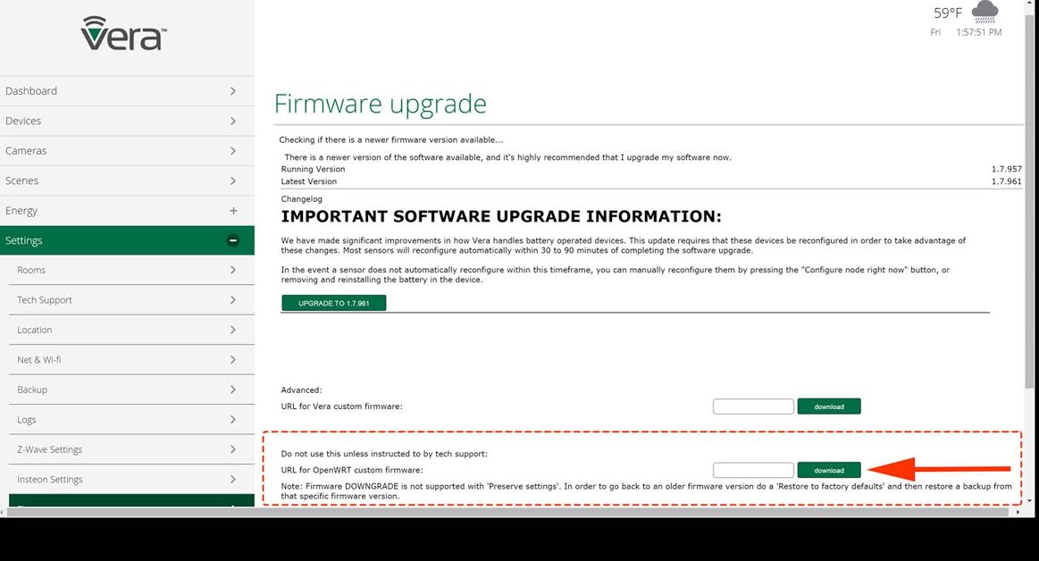
Vera Edge UI7 - Serial USB Fix!!!Following @mjunqueira post on creating a Vera support ticket, I decided to do the same. The support team at Vera send me a link to do a firmware update that will fix the "Serial USB issue". I followed the steps and it has been working great for me so far.
Step 1
Do a Backup. Just incase it fails to update, you have your previous settings.
Step 2
Cut and paste the following hyperlink http://download1204.mios.com/firmware/os_mt7620a/openwrt-ramips-mt7620a-na301-squashfs-sysupgrade-107.bin into the “URL for OpenWRT custom firmware:” field (image attached) on the Firmware page, under settings and follow the user prompts.

Step 3
There will be two options "Backup or Update Firmware". ... Select Update Firmware.
Sit back, relax and follow the instructions.The whole process will take approximately 15 mins or less.Step 4
Configure Serial Port and My Sensor

Cheers!
-
Array Relay Button ActuatorThe following sketch has got what you're looking for. Hope that helps.
Relay With Actuator Switch Toggle
#include <MySensor.h>
#include <SPI.h>
#include <Bounce2.h>
#define RELAY_ON 0                      // switch around for realy HIGH/LOW state
#define RELAY_OFF 1

MySensor gw;

#define RADIO_ID 11                    // Radio ID, whatever channel you assigned to
#define noRelays 6
const int relayPin[] = {A0, A1, A2, A3, A4, A5};
const int buttonPin[] = {3, 4, 5, 6, 7, 8};

class Relay				// relay class, store all relevant data (equivalent to struct)
{
public:
  int buttonPin;			// physical pin number of button
  int relayPin;				// physical pin number of relay
  byte oldValue;               		// last Values for key (debounce)
  boolean relayState;             	// relay status (also stored in EEPROM)
};

Relay Relays[noRelays];
Bounce debouncer[noRelays];
MyMessage msg[noRelays];

void setup(){
	gw.begin(incomingMessage, RADIO_ID, true);
	delay(250);
	gw.sendSketchInfo("MultiRelayButton", "0.9b");
	delay(250);

	// Initialize Relays with corresponding buttons
	for (int i = 0; i < noRelays; i++){
	Relays[i].buttonPin = buttonPin[i];				             // assign physical pins
	Relays[i].relayPin = relayPin[i];
	msg[i].sensor = i;						             // initialize messages
	msg[i].type = V_LIGHT;
	debouncer[i] = Bounce();						     // initialize debouncer
	debouncer[i].attach(buttonPin[i]);
	debouncer[i].interval(5);
	pinMode(Relays[i].buttonPin, INPUT_PULLUP);
	pinMode(Relays[i].relayPin, OUTPUT);
	Relays[i].relayState = gw.loadState(i);			                      // retrieve last values from EEPROM
	digitalWrite(Relays[i].relayPin, Relays[i].relayState? RELAY_ON:RELAY_OFF);   // and set relays accordingly
	gw.send(msg[i].set(Relays[i].relayState? true : false));	              // make controller aware of last status
	gw.present(i, S_LIGHT);							      // present sensor to gateway
	delay(250);

	}
}

void loop()
	{
	gw.process();
	for (byte i = 0; i < noRelays; i++){
	debouncer[i].update();
	byte value = debouncer[i].read();
//	if (value != Relays[i].oldValue && value == 0){
        if (value != Relays[i].oldValue){
	Relays[i].relayState = !Relays[i].relayState;
	digitalWrite(Relays[i].relayPin, Relays[i].relayState?RELAY_ON:RELAY_OFF);
	gw.send(msg[i].set(Relays[i].relayState? true : false));
	gw.saveState( i, Relays[i].relayState );}                 // save sensor state in EEPROM (location == sensor number)

        Relays[i].oldValue = value;

	}
}

// process incoming message
void incomingMessage(const MyMessage &message){

        if (message.type == V_LIGHT){
        if (message.sensor <noRelays){ 	 // check if message is valid for relays..... previous line if [[[ (message.sensor <=noRelays){ ]]]
        Relays[message.sensor].relayState = message.getBool();
        digitalWrite(Relays[message.sensor].relayPin, Relays[message.sensor].relayState? RELAY_ON:RELAY_OFF); // and set relays accordingly
        gw.saveState( message.sensor, Relays[message.sensor].relayState ); // save sensor state in EEPROM (location == sensor number)
		}
	}
}
