Hello,
maybe I am the only one, for weeks I receive email notifications twice a day, at the same time.
Hello,
maybe I am the only one, for weeks I receive email notifications twice a day, at the same time.
Hello,
few years ago I was searching a technic to measure water level in a small tank.
I have read somewhere that some motorbike have a gaz tank that use a "capacitance level meter".
I have never succeeded but you may have a try.
I have just found an example to illustrate:
Hello,
I have not used SHT30 yet, but as an I2C device it should not be a problem to wire it.
On Arduino UNO: SDA is A4 and SCL is A5.
I2C is not designed for "long wires" (not sure maybe <1m), you may have to put your Arduino near your SHT30.
The ethernet module and NRF24L01 use SPI bus, did you succeed to make them both working on the same Arduino ?
I have just found that another kind of detection exists: optical
cf: https://www.yoctopuce.com/EN/article/how-to-build-a-rain-sensor
I wonder how hard is it to be able to reproduce it.
Hello @TheoL ,
I better understand now, you are right this kind of sensor could be useful
I imagine that you have already found this page: https://www.avdweb.nl/arduino/measurement/rain-detector
It seems to use the same sensor. Reading it, I have just understand that the bottom was for heating, nice.
Hello @TheoL
I have not good experiences with rain sensors,
the only one that "works", does not cost an arm and relatively simple to make it to use a rain bucket counter.
I have found that wireless ones (radioร 433Mhz) were twice cheaper than "wired" one,
and you can easily "wirefy" by juste soldering two wires on the "magnetic switch" and cutting a trace or two. cf: bad picture from years ago https://raw.githubusercontent.com/Jodaille/LyceeDesAndaines/master/JaugePluieInterruption/Soldered_wires_for_contact.jpg
Thank you @rvendrame ,
it works, I attach a Ceech's schema, using D4 instead of D3
Hello @Yveaux, hello @rvendrame: thank you.
the led is still alive
With the sketch , I can see the led blinking if it is wired between gnd and d3.
@rvendrame I should miss something because the led stay off with your instructions.
Maybe @ceech will see this my SOS
Hello,
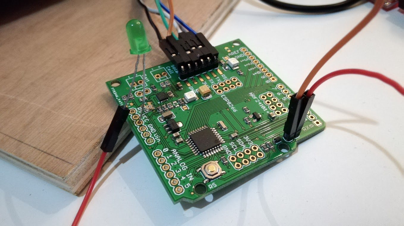
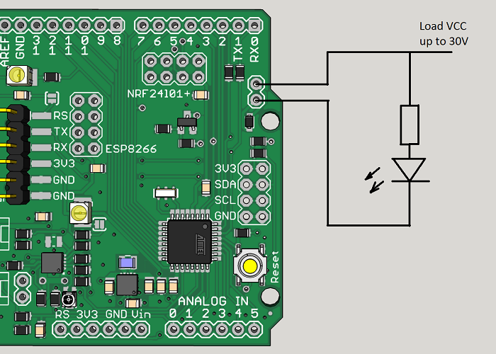
I would like to use the mosfet of the Ceech board: ATmega328p board w/ NRF24l01+ socket LTC4079
In the doc is indicated that it is wired do digital 3.
I have modified the "blink without delay" sketch
const int MOSFET = 3;
int loadState = LOW;
unsigned long previousMillis = 0;
const long interval = 2000;
void setup() {
// put your setup code here, to run once:
pinMode(MOSFET, OUTPUT);
digitalWrite(MOSFET, HIGH);
Serial.begin(9600);
}
void loop() {
unsigned long currentMillis = millis();
if (currentMillis - previousMillis >= interval) {
// save the last time you blinked the LED
previousMillis = currentMillis;
// if the LED is off turn it on and vice-versa:
if (loadState == LOW) {
loadState = HIGH;
} else {
loadState = 0;
}
// set the LED with the ledState of the variable:
digitalWrite(MOSFET, loadState);
Serial.print("state: ");Serial.println(loadState);
}
}
I don't understand how it works, I have tried to measure continuity with a voltmeter, I have tried to wire a led between vcc, cuting the gnd with the mosfet without success.
Does anyone would be explain how I can use it ?
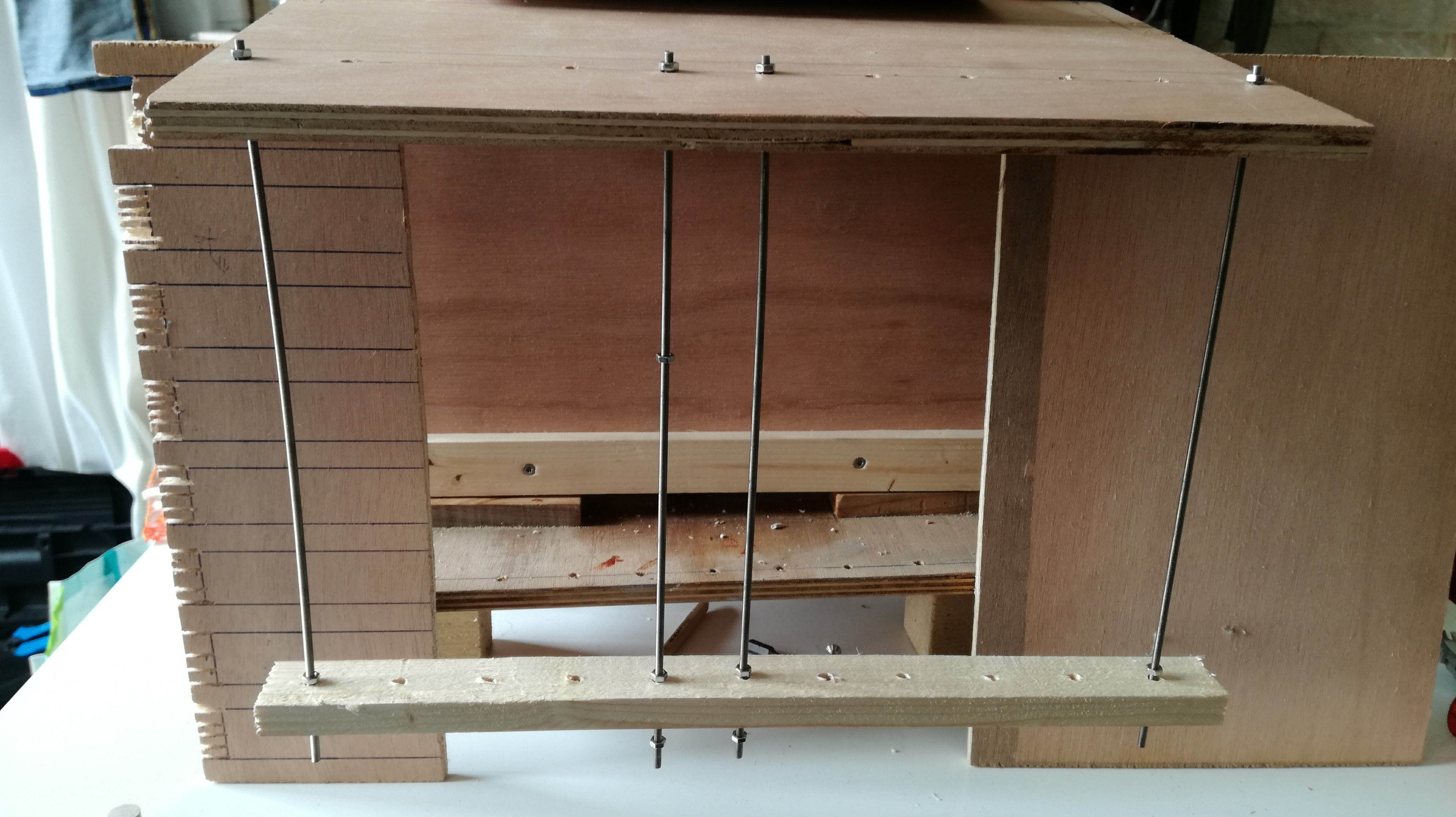
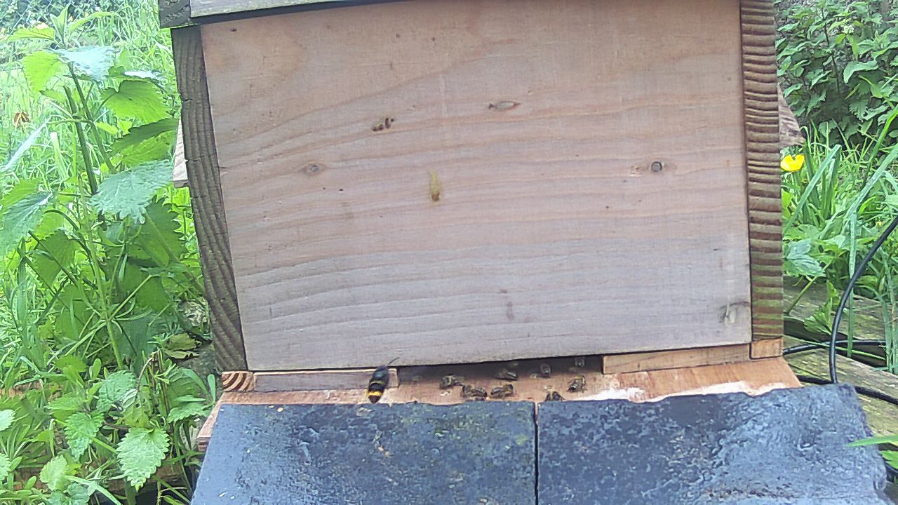
I would like to make an electrical barrier to protect my beehive from vespa velutina using a mosquito racket :
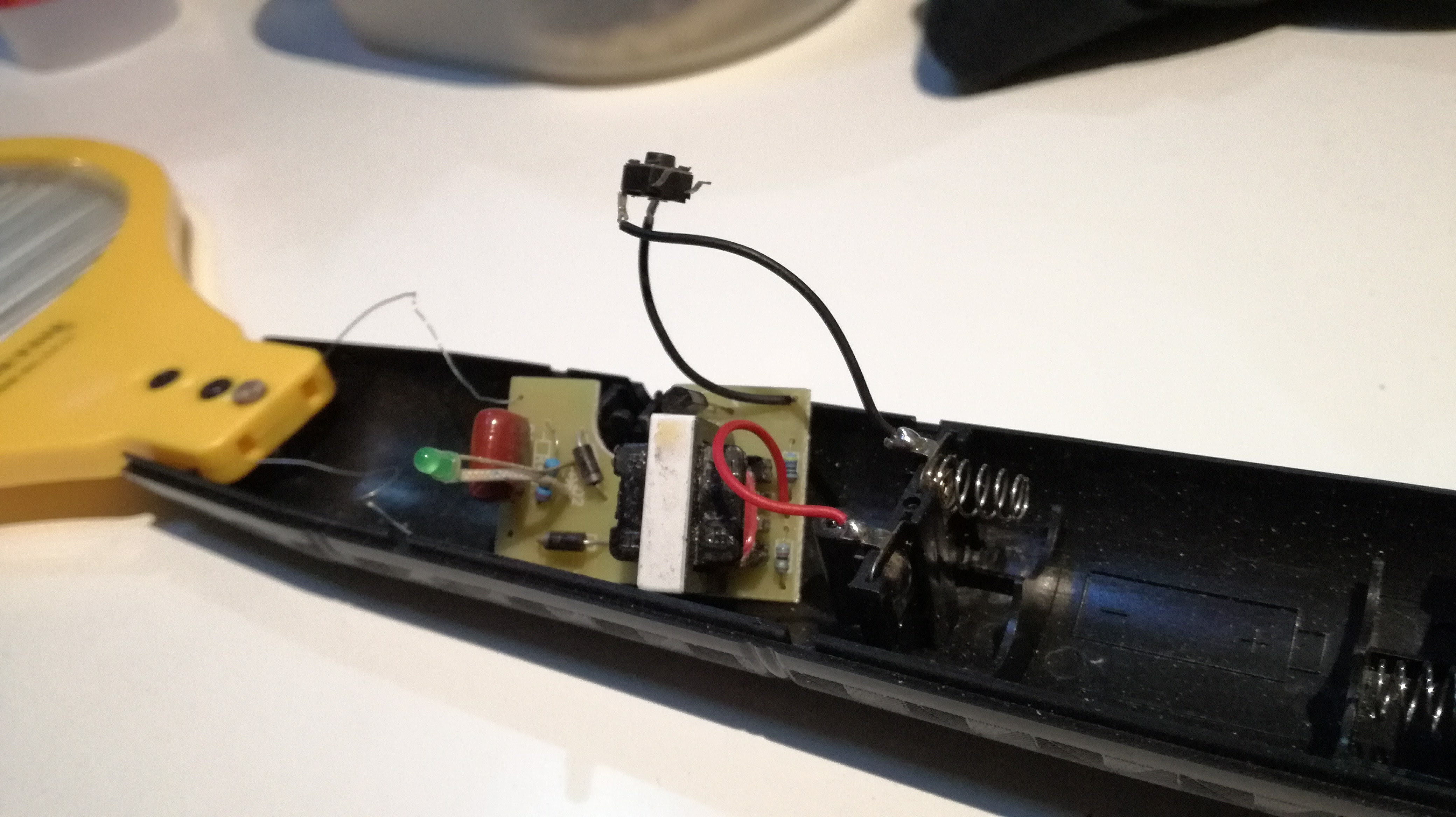
Hello Ceech,
your board is used with six ds18b20 sensors to monitor a hive:
Hello,
we have successfully transmitted data over 233 m (apiary to labo) with RFM69.
@tomkxy said in Ceech-Board Buyers:
I bought twice @ceech and delivery was prompt. Also all questions I had were promptly answered. So I would buy from ceech again without hesitating.
Me to, thank you Ceech ! Solar board is awesome
Hello,
now it is charging \o/
Vcc = 3.28V
Charge current = 71.65mA
Solar cell voltage = 4.71V
Battery voltage = 3.97V
CHRG = 0
it was Battery voltage = 3.90V few minutes ago
Hello Ceech,
thank you for your answer,
@ceech said:
Charge current is the current that flows into the battery. And the CHRG signal indicates when charging occurs. CHRG is an active low signal. It means that charging works when this signal is 0 or close to zero.
So I think I have turned the trimmer too much
Your board is very useful, it is very nice to be able to monitor level battery and so on !
Hello,
I am using Ceech board (LTC4079) with 6v pannel
I have tried to adjust potentiometer but I am not sure to well understand the values :
Vcc = 3.28V
Charge current = 0.00mA
Solar cell voltage = 5.56V
Battery voltage = 4.03V
CHRG = 542
I read CHRG = 542 but Charge current = 0.00mA
If I turn a bit the portentiometer I have :
Vcc = 3.28V
Charge current = 79.91mA
Solar cell voltage = 4.95V
Battery voltage = 4.07V
CHRG = 0
What I understand is that charge current come from solar cell and CHRG is amount send to battery, am I right ?
Is it normal to nat have a positive value in both ?
ps: for now with full wires (power and network) it looks like http://jodaille.org/snapshots/
a daily timelapse and meteo/temperature sensors