Navigation

    • Register
    • Login
    • OpenHardware.io
    • Categories
    • Recent
    • Tags
    • Popular
    1. Home
    2. Mishka
    3. Posts
    • Profile
    • Following
    • Followers
    • Topics
    • Posts
    • Best
    • Groups

    Posts made by Mishka

    • RE: CNC PCB milling

      Here is a fiber laser machine example: https://mylasermart.com/product/ultra-high-speed-laser-machine/

      It uses 50W fiber laser. Minimal track width is 0.05 mm! Space between tracks is 0.025 mm which is limited by the beam size. Precision Β±2 Β΅m.

      This particular one doesn't look any cheap, but it gives the strong hint what to look for.

      posted in General Discussion
      Mishka
      Mishka
    • RE: CNC PCB milling

      @NeverDie Yeah, it's a very interesting option! Similar approach might be to use a UV printer. The UV paint is known to be resistant to FeCl3 and hence results in nice and clean edges. But that's subject of paint and a laser engraver could be used over UV paint too.

      On the other hand, a fiber laser might be a nice all-in-one solution. It can do the PCB routing, can cut the board edges, and drill everything in one pass. After that, the same device can be used to manufacture solder mask using a kapton tape and also engrave the silk layer on top of it. Finally, it can cut stencils.

      The only missing part is the through hole plating. I still have concern that laser drilled the edges will be good enough for metalization, this has to be checked. But a previously drilled and plated board is much easier to etch with laser rather than a milling machine.

      posted in General Discussion
      Mishka
      Mishka
    • RE: πŸ’¬ The Harvester: ultimate power supply for the Raybeacon DK

      @NeverDie Yeah, this is awesome hack! I'll followup in the CNC thread πŸ‘

      posted in OpenHardware.io
      Mishka
      Mishka
    • RE: πŸ’¬ The Harvester: ultimate power supply for the Raybeacon DK

      Regarding the PCB milling, I found myself thinking fairly often about full-cycle manufacturing too πŸ™‚

      I usually do small boards, up to 4x4 inch. For this size it should be possible to build an affordable, but highly capable machine. Some thoughts on it:

      • High precision. The machine must be able to cut tracks and pads as thin as 6 mils (0.15 mm), but 5 mils would be really nice to achieve. Because of this I'm more inclined to laser cutting. On a milling machine 6 mil gaps between tracks will be hard to do. Another advantage of laser cutting is that it won't tear tiny tracks off the board. Perhaps, even a copper foil can be laser cut. But there's also a spoon of tar: the copper is known to be very reflective and imposes higher requirements to the laser cutter - the price may increase. Another thing to note is that the laser may be not so good at removing large surface areas.

      • Kapton tape for solder mask. For sticky mask to apply, I'm also thinking about some kind of a pallet - this would allow to use cheap polyimide tapes from eBay. Alternatively, non-sticky masks can be laminated. Laminated masks will stick stronger and can be two sided - think of it as about three and more layers. Again, laser cutting is preferred here.

      • Engraving of the silk layer. Laser could be also used for high-res silk layer over the kapton tape. With laser used, the difference in distances from the head to surface because of the copper layer is not an issue. Engraving on both copper and substrate is also possible.

      • Interchangeable heads? Probably, no. The cost of the working head, either laser or milling, will likely dominate over the cost of other components - the machine is small. Seems it's more reasonable to have different machines.

      • Assembly machine. This would be my favorite, but first things first.

      posted in OpenHardware.io
      Mishka
      Mishka
    • RE: πŸ’¬ The Harvester: ultimate power supply for the Raybeacon DK

      Hi @NeverDie,

      The 39% is a HUGE!

      I think there is must some fundamental limit on how much we can get from these oscillations of the, well, Ether. Or is it the quantum vacuum? Or the strings? Well, the very last name to this kind of shit is the time crystals. And, no matter what the name is, the shit can oscillate, and these oscillations are the essence of the energy. So, while currently most of electronic devices employ electrons as drivers, I'm wondering would it be possible to build an electron-less system where the oscillations (aka waves) may be passed through a number of transformations, and this will bring us to some useful things.

      Actually, there is RF and optics which works exactly like that. There is also a number of RF harvesters to collect the energy, but the energy is used mostly to push electrons forward, i.e. produce direct current. That's understandable - most of devices are DC. But creating some kind of a microwave transistor would be just rad.

      posted in OpenHardware.io
      Mishka
      Mishka
    • RE: πŸ’¬ The Harvester: ultimate power supply for the Raybeacon DK

      Gah! I've lost the ball 😞

      No progress on discrete harvester, sorry. Also, the PV panels I got earlier were shelved until better times.

      I still monitor a couple of the SPV1050 devices though. They're running from various PV panels that I switch from time to time. The load is an nRF52833 beacon and sometimes an IMU broadcasting every one second at 0dBm to 8dBm and reporting voltage of attached ML2032 battery to my phone.

      My experience is that a tiny PV panel cannot sustain the device working online. By online I mean that both the device and the harvester power consumption exceeds the panel capabilities, so the battery slowly decays. A bigger panel can address the issue. I still unsure how much we will win if a more efficient online harvester like AEM10941 or even more efficient R1800K will be used. A batch harvester is definitely the way to go.

      But how about you? Have you had a chance to build anything yet?

      posted in OpenHardware.io
      Mishka
      Mishka
    • RE: πŸ’¬ The Harvester: ultimate power supply for the Raybeacon DK

      @NeverDie Yeah, soldering those tiny packages is sort of PITA. For experimenting with them I thought on a breadboard friendly PCB with the package footprint.

      posted in OpenHardware.io
      Mishka
      Mishka
    • RE: πŸ’¬ The Harvester: ultimate power supply for the Raybeacon DK

      Hi @NeverDie,

      I also have the strong feeling that a couple of voltage detectors could make it much easier, yet – due to picoamps leakage – more effective.

      Such, in the couple of last days I've tried to reproduce the UB40M circuit with real transistors. Perhaps, when you build a die you can construct every transistor with the parameters you need, but I admit it was not a trivial task to pick anything suitable from a catalogue. I defined no strict constraints to the application, rather tried to be opportunistic and use whatever works. There were some assumptions though:

      • Input voltage is defined by the solar cell and is somewhere between 2V and 3V. In the deign below it's set to 2.5V.
      • The short circuit current for the cell should not extend 50 nA. I've limited it down to 25 nA with the Rcell = 2.5V/25nA = 100MΞ©.
      • The harvester should be able to charge 22Β΅F storage capacitor - this capacity should be enough to send a single non-connectable BLE advertisement.

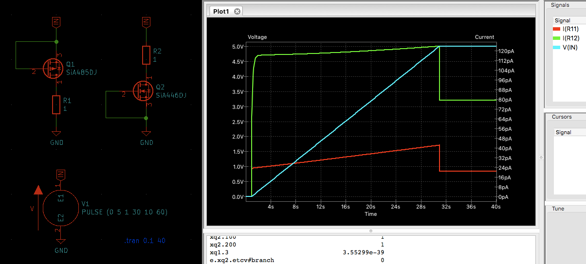
      I haven't bothered to find the low leaking MOSFETs and chose something small, handy to solder, cheap, and in stock. That turns out to be power MOSFETs in PowerPAK SC-70 package from Vishay. The nomenclature is SiAxxxDJ where the xxx is what you may see in the circuitry below. For example, 421 stands for SiA421DJ.

      91e32ff1-904a-4d2a-a80a-2ac6b58e0c88-image.png

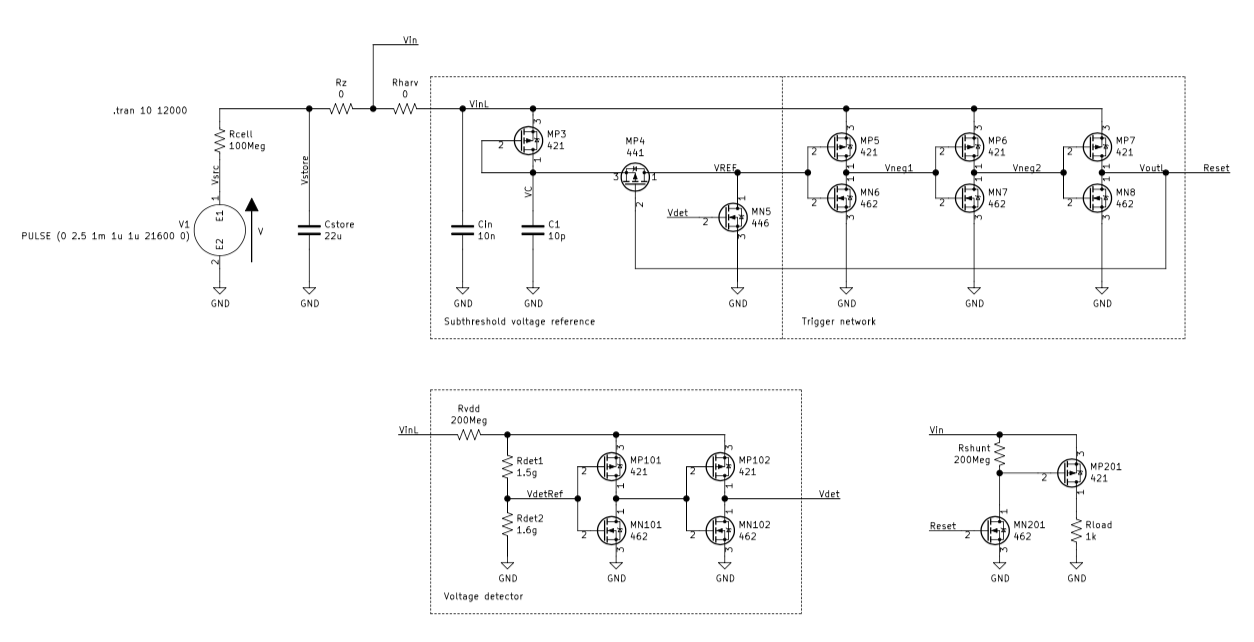
      The core of the circuit is the pretty much of the UB40M reference design. The series of MP5-MP7/MN6-MN8 triggers will pull Reset line high when VREF will become low. This will happen when MN5 will pull it down, and depends on the Vdet voltage. At the same time, the MP4 will be turned off by VoutL (Reset) thus preventing VinL from being unintentionally pulled to the GND. The MP3 is used as a diode there.

      I failed to create the VREF voltage in the way it was defined in the Bristol paper. With the circuit powered by the very low-power source, it suffers from transient processes a lot. To address that, I went for more complicated solution with couple of triggers controlled by Rdet1+Rdet2 divider. The divider also allows to tune the circuit to better match source and storage capacitor.

      Finally, there is a 1k load attached to the Vin line. It discharges the Cstore capacitor as soon as the Reset will be set high. Upon discharge, the voltage detector will went reset the Vdet and the Cstore will be charged back.

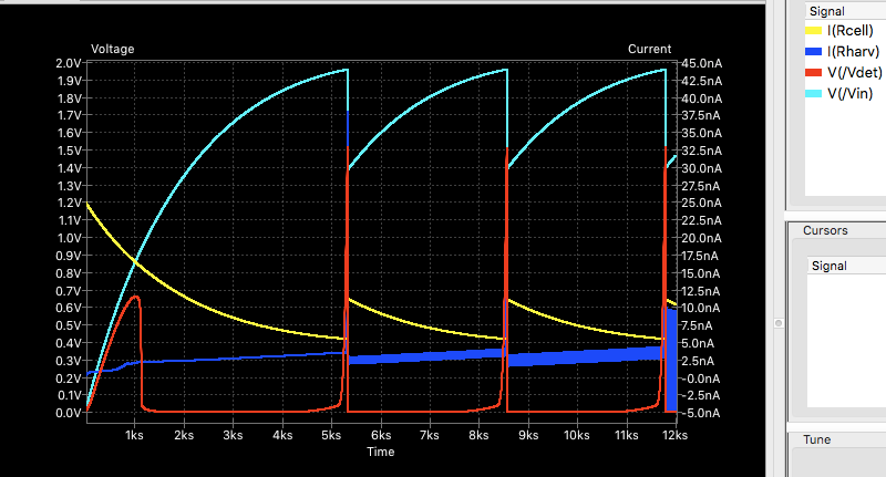
      In my KiCad ngspice it looks as follows. With Vcell=2.5V, Icell=25nA the Vin oscillates between 1.4V and 1.95V. Although this is way below required 1.8V for most of sensors and MCU, raising solar cell voltage to 3.5V will shift the voltages to the usable range.

      Discharge current is limited solely by the Rload=1k. At the same time, average current consumption of the harvester is about 3nA - the blue line I(Rharv). Solar cell load is below 10 nA - the yellow line I(Rcell). However, due to non-linear nature it's hard to predict how the line will look like with a real cell. Probably, it's better to simulate it with a current source, I don't know. The red line Vdet shows how the voltage detector works.

      381edfa1-9db2-4463-b56d-5ba953fcef10-image.png

      To be honest, I'm quite unhappy about the circuit.

      First of all, it uses a lot of transistors, please compare this to the BJT harvesters you're working on. Also, many of them work on subthreshold voltages, and this makes it relatively hard to to tune. But worse, real devices will likely to suffer from the voltage interference which makes the whole circuit too fragile. Taking in account the money to build it (even with $0.40 per FET), it turns out the circuit shall be considered rather impractical.
      πŸ€·β€β™‚οΈ

      posted in OpenHardware.io
      Mishka
      Mishka
    • RE: πŸ’¬ The Harvester: ultimate power supply for the Raybeacon DK

      @NeverDie said in πŸ’¬ The Harvester: ultimate power supply for the Raybeacon DK:

      Glad you asked, but it turns out not to be happy news. As it stands, it's a very constant 28.73ua leakage, which is obviously pretty terrible.

      The circuit has so low leakage mostly due to the gigohmic resistors. In particular, those 300 pA bumps on AM3 may be due to the R4 limits (3V / 10 gOhm). And it looks like the right thing to do for a BJT. Oppositely, MOSFETs can be used as ultra strong resistors themselves. I.e. should you put several in series and the leakage drops.

      I.e. it might be reasonable to drop a MOSFET in the place of T5+T6, and yet another gigohm resistor will cut the T4 leakage down.

      posted in OpenHardware.io
      Mishka
      Mishka
    • RE: πŸ’¬ The Harvester: ultimate power supply for the Raybeacon DK

      @NeverDie said in πŸ’¬ The Harvester: ultimate power supply for the Raybeacon DK:

      Maybe this kind of separation better answers your question about the leakage?

      Definitely. Thanks a lot!

      It would also be interesting to know measurement from the AM4 when the LED driver circuit is off. You see, MOSFETs are mainly characterized by the subthreshold leakage current between D and S - the AM4 has it.

      posted in OpenHardware.io
      Mishka
      Mishka
    • RE: πŸ’¬ The Harvester: ultimate power supply for the Raybeacon DK

      @NeverDie Congratulations! Looks very holistic. The only model needed is 2SD2704 - cool! 🀘

      I'm unsure though will it be possible to substitute the star from three 100 pF capacitors with a single one 68pF?

      Could you also isolate T4 and T5 from the oscillator, please, so the AM1 won't measure their leakage? It's interesting to compare that cascade to a MOSFET.

      posted in OpenHardware.io
      Mishka
      Mishka
    • RE: πŸ’¬ The Harvester: ultimate power supply for the Raybeacon DK

      @NeverDie said in πŸ’¬ The Harvester: ultimate power supply for the Raybeacon DK:

      Unless you can think of a way to somehow roll-your-own ultra low power supervisor, I'm not aware of anything else. I suspect that maybe the Michigan team that built the Cortex M0 with the ultra tiny solar cell could easily beat both the ABLIC and Vishay supervisors--I'm still gobsmacked by what the Michigan team accomplished-- but at the moment I don't understand how to do the kind of leakage supression that's the foundation of what the Michigan team did. On my one and only attempt, after toying around with it, I was able to get one simulation that seemed to oscillate under very narrow conditions without meaningful leakage, and at first that gave me some hope. However, at the time I didn't see a way to extend that tiny, somewhat dubuious success toward anything useful. Having read the Michigan paper, can you get a leakage supression simulation working, either from their schematic or from one of the other papers? If so, that would be enormously helpful. I could post the simulation that I tried if you wanted to take a stab at it. It's not much, but pretty much anything, even an unremarkable crippled anything, is more than what typically gets published in the academic papers.

      IMHO this is the promising direction to go. I haven't analyzed the circuits yet, but the super cut-off idea is dead simple - instead of grounding transistor gates, they have to be under-driven with a negative voltage. This should effectively remove free electrons from the depletion region and hence minimize drain–source leakage. Unfortunately, this requires to maintain an additional negative power source which may draw it's own current to operate. The overhead may be to expensive for a circuit with few gates, but seems well worth it for a processor core with thousands of transistors. What's good, is that this technique clearly separates optimization from the logic. In SPICE it might be easily simulated with a second voltage source, for example, at -0.1V. BTW, for the same reason the higher Vth - the lower DS leakage should be expected.

      I'm thinking about building the UB40M alike circuit with any transistors. Well, the FemtoFET series is very small indeed. But size of the biggest package codename F5 is 0.73x1.49 mm which is roughly the same size as 0603 components. With proper PCB footprint soldering them should not be an issue. All in all, what must we expect from a modern high performing transistor?

      Unfortunately, my ngspice doesn't work well with the Level 7 model the TI provides. So to have anything tangible to play with I've noticed a complimentary pair from Vishay, Vth=2.5V, Vds=150V: SiA485DJ (P-channel) and SiA446DJ (N-channel). PowerPak SC-70 package also looks appealing - 2x2 mm will help save PCB space, but still not microscopic.

      Unfortunately, the P-MOS has no SPICE model, damn it. I'll try to replace it with Si1411DH which parameters looks very close to the SiA485DJ, and there are SPICE models for it.

      Some leakage curves for the FETs in the 0...5V range:

      0f52c7b2-cb66-4183-a508-97b39f1822c4-image.png

      Interesting, that the faster raises the voltage - the more leakage occurs. For example, the same chart for 1s raise:

      22b2b682-75c2-487e-83dc-56dfd7f0fb9a-image.png

      posted in OpenHardware.io
      Mishka
      Mishka
    • RE: πŸ’¬ The Harvester: ultimate power supply for the Raybeacon DK

      @NeverDie Cool! πŸ‘

      A supervisory circuit will be needed between the store and the load anyway. BTW, most of ultra-low power supervisors will consume tens of nanoamps. Does it mean it has to be a low leaking FET? πŸ™‚

      posted in OpenHardware.io
      Mishka
      Mishka
    • RE: πŸ’¬ The Harvester: ultimate power supply for the Raybeacon DK

      @NeverDie said in πŸ’¬ The Harvester: ultimate power supply for the Raybeacon DK:

      a couple of interesting things about the NPN ring oscillator are worth mentioning:

      It works over a wide voltage range: from 300mv up to 20v.
      In contrast to the NFET ring oscillator, where when an NFET is "OFF", it continues to leak current, in the NPN ring oscillator, when the NPN is "OFF", it leaks almost no current at all--maybe just a couple picoamps or less.

      Yeah, it is impressive, no doubt. I'm not confident with so low-power circuits and were taught that MOSFETs are leaking less, and BJTs are requiring more current to drive. But this discussion disregards it all, at least when it comes to discretes πŸ˜„

      posted in OpenHardware.io
      Mishka
      Mishka
    • RE: πŸ’¬ The Harvester: ultimate power supply for the Raybeacon DK

      @NeverDie Regarding components selection - unfortunately, that's true, too few manufacturers provide that data in a table to compare and select from. So far we have the FemtoFET series from Texas, the FETs listed in the Nexperia's AN90009 paper, and the ALD FETs. General recommendations for a low-lakage FET may be:

      • Higher gate–source bias voltage. Obviously, the higher voltage required to turn a FET on - the more resistance between gate and source, and the less leakage.
      • Higher source-drain resistance when on. It simply means the FET will have higher resistance when closed too.
      • Protection diode may also cause some leakage.

      However, an attempt to select low-leakage FETs using these recommendations will certainly fail. It rather seem more depends on specs a manufacturer tries to warrant. For example, in theory high drain-source voltage may imply lower leakage at low voltages. But usually lower power transistors are leaking less.

      Such, all Vishay specs I've read for more or less matching transistors mention exactly the same values for GS and DS leakage. Similarly, all ALD transistors have very low leakage because the ALD is working hard to manufacture them so. But I admit, for unknown reason any of those low-leakage FETs are ridiculously small, it's very rare when any dimension is bigger than 1mm.

      Looks like if we really want it low, we must accept the size. On the other hand, some youtubers do solder even 008004 which are way smaller.

      Alternative way is to choose a couple of transistors and measure them. I think that 1Β΅A leakage from datasheet will barely go over 10nA in practice, so your choice should be just fine.

      BTW, SPICE models usually operate with physical dimension, so should be accurate enough when it comes to comparing leakage of different items.

      posted in OpenHardware.io
      Mishka
      Mishka
    • RE: πŸ’¬ The Harvester: ultimate power supply for the Raybeacon DK

      @NeverDie In SPICE the ring oscillator works just fine. I don't see why it may be hard to have it oscillating with any FET. However, due to the fact it's perfectly balanced (at least in it's current form) across all the three transistors it may be somewhat reluctant to start.

      Here is how I get it in the light of the power consumption. For convenience, I've re-enumerated all components left to right.

      779c6f8a-8c5a-488b-b8a0-27db94364dcf-image.png

      Phase 1. I'm not going to cover the circuit boot and will start at the moment when the Q3 is closed. In the closed state VF3=0 it will tie the Q1 gate and the bottom pole of C1 to the ground. The Q1 is closed, and the C1 will be charging via R1 resistor. The R1 will set the charge time for C1.

      At the same time, due to the closed Q3 the voltage source will be grounded via R3 and this results in extra leakage Vin/R3. At this phase, the overall current consumption will be about I β‰ˆ Vin/R2 + Vin/R3

      Phase 2. The phase 1 will last until C1 will be charged to the Q2 gate threshold voltage. After that, the Q2 which was previously open due to the C1 voltage drop, closes, and this will tie VF2 to the ground and open the Q3.

      The opened Q3 will shift ground level for the C1 thus doubling the VF1 voltage. The C1 will start discharging down to zero until VF1 won't balance VF3. Actually, the C1 it will be charged from the opposite side via R3. The R3 defines period of the stage 2. Consumption current should be about the same I β‰ˆ Vin/R2 + Vin/R3. Please note, since the Q2 is not participating in C1 charge/discharge it should be safe to keep R2 resistance much higher than R1 and R2, like 300g or so, and decrease the circuit consumption.

      However, it seems slightly more complicated than that. Due to FETs non-linearity, at marginal gate voltages there is some drain–source resistance. Despite the Q1 is open with VF3 voltage, it's not enough to have the C1 grounded, and this is why the circuit works at all. Instead, both C1 and the voltage source will be leaking via the Q1. While voltage source is limited by R2, the leakage for C1 may be quite high and require extra attention. Luckily, this is not true for the SiSA40DN - the C1 slowly discharges via Q1 and this compensates for leakage from the voltage source via R1.

      Repeat. Upon C1 discharge it's going to close Q2 and raise gate voltage on Q3. The Q3 opens, VF3 voltage drops, then Q1 closes too, and the C1 starts charging back again.

      Well, as for an astable oscillator the circuit looks cool, definitely would be interesting to build. But for energy harvesting purposes I'd prefer some UB40M variation - IMHO it's much cleaner from the point of parasitic leakages. Especially if taking in account those leakage optimization techniques like we've seen for the super cutoff gates.

      posted in OpenHardware.io
      Mishka
      Mishka
    • RE: πŸ’¬ rayBeacon: nRF52 on-the-go Development Kit

      So, while here I've decided to close my TODO list. The revision 1.4 is likely to be the last chapter in this design, and now it can be considered safe to order. It introduces some important final touches to the board, in particular:

      • The orientation key (diameter 2.1mm) on the board edge. It's located between the Tag-Connect and the board main area, and initially can be used as an eyelet. After the Tag-Connect removal it works as an orientation key for the board.

      • Full rework of the silk layer. Just to mention few: I hid all designators and decorated the board with eye catchy "52" over the nRF52 MCU, touched the antenna outline, and moved the git hash to the mainland.

      • Review and cleanup the ground plane. The changes were tiny so it shouldn't detune the antenna, but aesthetics were definitely improved. You may also want to order the board in Afterdark colors now:

      raybeacon-afterdark.png

      Have fun!

      posted in OpenHardware.io
      Mishka
      Mishka
    • RE: πŸ’¬ rayBeacon: nRF52 on-the-go Development Kit

      The revision 1.3 is here! It adds hardware RESET feature to the SW2 push button, as well as to the SWD port. Not a big deal when attached to debugger, but so handy on the go.

      Please note, the change make break your firmware because SW2 was mapped to P1.02 GPIO and now linked to the P0.18 / RESET.

      posted in OpenHardware.io
      Mishka
      Mishka
    • RE: πŸ’¬ The Harvester: ultimate power supply for the Raybeacon DK

      @NeverDie The circuit looks like a parametric oscillator indeed, and it is cool! What I like about it (of course, if I get it right) is that it employs only one transistor model, and those gigohm resistors are maintaining the current consumption really low. For this reason there is no need to carefully select the transistors - everything that has appropriate gate threshold value should work just fine.

      On the other hand, it might happen that if you need it to work at higher frequency you will have to lower resistance of the R1-R3 and thus increase the current consumption.

      BTW, accordingly to datasheet those particular FETs has quite high D-S leakage up to 1 Β΅A. But again, should not be an issue. Perhaps, while you're here and have tools to measure picoamps, you might be interested to grab a couple of those Femto N-FETs or other officially low leakage transistors, just to compare them to others. In particular, put them against a usual FET in the super-cutoff state, i.e. when supplying negative gate-source voltage.

      And, of course, I wish you best of luck with this experiment ☣ and look forward for your updates! 🀞

      posted in OpenHardware.io
      Mishka
      Mishka
    • RE: πŸ’¬ The Harvester: ultimate power supply for the Raybeacon DK

      @NeverDie More than enough πŸ™‚

      It seems there are two more or less working BJT based circuits which can be tested easily - the 3 nA oscillator which you've modeled with different transistors, and the solar motor project. Both are way more low-power than existing harvesters.

      The FET based circuit remains in doubt until suitable components were selected. But IMHO putting some FETs to test to measure D-S leakage would surprise with numbers.

      Regarding application, I have no requirement for so ultra-low power system, but many examples do measure something and then broadcast the data via BLE. They may even use harvesting switches, like the On Semi BLE-SWITCH001-GEVB evaluation kit. Maybe we can also consider something like this? If you have any good app on your mind lets aim at it.

      posted in OpenHardware.io
      Mishka
      Mishka
    • RE: πŸ’¬ rayBeacon: nRF52 on-the-go Development Kit

      Hi guys, FYI the revision 1.2 just came out.

      After using the board for a while some non-critical fixes were introduced. To mention few:

      • The RGB LED got color and current optimizations. It's also recommended to stick to green or blue to minimize current consumption.
      • The breadboard adapter was inconvenient to cut-off and now fixed with a less fancy outline.
      • The board got AEC-Q200 qualified 32768Hz crystal.

      There are still some items on my TODO list (in particular, I'm not too happy about the extension socket - it can do more, and I'm going to address that separately), but the board is quite handy and definitely works. For this reason I think it's time to reset the W.I.P. bit and call the project stable.

      posted in OpenHardware.io
      Mishka
      Mishka
    • RE: πŸ’¬ The Harvester: ultimate power supply for the Raybeacon DK

      @NeverDie Wow, my congratulations on making so much progress! Diving below 1nA is serious achievement!

      The paper on the batteryless sub-nW Cortex-M0 shows a state of the art circuit built with FETs in super cut-off state. Thanks for finding it! But this makes me think that from all the networks we've considered here - the 3nA oscillator by David Johnson, the ready to use 10nA solar-powered motor driver by Stepan Novotill, and the UB40M chip by Bristol - due to some leakage elimination techniques a MOSFET based circuit might have the best performance anyway. The essay on femtoampere circuits also suggests FETs for lower leakage. (But I admit I still extremely impressed about those two BJT circuits.)

      The relaxation oscillator with 230 fJ/cycle efficiency is also voltage driven, i.e. based on MOSFETs with proper threshold. Similarly to the UB40M it uses capacitors for time adjustment. By chance, detailed description is available for free as part of the Ultra-low energy electronics for synthetic biological sensors paper, please see chapter 3.

      Components selection still play important part here, but assuming no femtoamp level I don't think package size will be too important. Enough clearance around elements may work similarly well. Regarding threshold values, the bigger voltage should be applied to the gate in order to close the transistor, the less leakage current between source and drain may be expected. This is exactly the reason why super cut-off state gates are working so well. The nice overview of this and other leakage elimination techniques described in the Design and Modeling of Low Power VLSI Systems book the relevant chapter from which is available as a dedicated paper. Perhaps it could help optimize current leakage later when the concept will be more or less ready.

      The pragmatic question still how the desired circuit should work. I think the major finding was that a-Si cells are capable of high voltage in very low light conditions. This allows to avoid overhead and complexity coming from extra charge pumps or other regulators, and drive MCUs and sensors (usually working in 1.8V to 3.6V range) from a store capacitor charged directly from the a-Si cell. Another big advantage is that such a circuit will have nearly zero cold boot current.

      How low should it go? The measured cell you use for experiments produce current in nanoamps, and when the cell current goes down to picoamps the voltage level seem also drops significantly. Also, waiting for the capacitor to charge from a picoamp source may take forever. IMHO targeting sources with few tens of nanoamps, and therefore maintaining the harvester self current less than 1 nanoampere should be considered a great success. Of course, the less quiescent current the harvester has - the better.

      For such a low-power source I'd expect the energy will be harvested for a long period of time (tens of minutes), and then dumped it all at once into the MCU and a sensor. Using the collected energy to charge a battery is impractical: modern devices require microwatts of energy, and the harvester simply can not withstand the consumption. For online operation a conventional harvester like the AEM10941 should be used.

      posted in OpenHardware.io
      Mishka
      Mishka
    • RE: πŸ’¬ The Harvester: ultimate power supply for the Raybeacon DK

      @NeverDie That's true, discrete transistors have not too thin parameters on paper. But assuming quite low voltages (about 3V) I'd expect those Nexperia and TI transistors may draw picoamps indeed. I think this is better to check with real devices. But assuming how small they are an evaluation board will be required. There are some, but it might be way cheaper yet more flexible to assemble such a module manually.

      For convenience, the custom PCB may also contain circuit required to measure the leakage. Perhaps a low-leakage capacitor may be charged to some known value, then a MOSFET (or number of FOSFETS in parallel) would discharge it for some time, and then the voltage drop can derive leakage.

      posted in OpenHardware.io
      Mishka
      Mishka
    • RE: πŸ’¬ The Harvester: ultimate power supply for the Raybeacon DK

      @NeverDie Nice reduce!

      AFAIU, the C1+M2 N-MOS will keep the trigger M6+M10 input low, and the output will turn high as soon as input voltage will reach the Vth threshold for the M10. Please note, the output will be limited by the R3=10g, so the circuit is kind of a voltage detector only.

      Have you tried it yet? How about making it oscillating? Also, could you explain please, what the M1 does?

      Please also note, for some reason the original network has the C1 protected with diode built into the MP3 P-FET. This probably should to be simulated with a diode rather FET. How do you think, why they need it?

      posted in OpenHardware.io
      Mishka
      Mishka
    • RE: πŸ’¬ The Harvester: ultimate power supply for the Raybeacon DK

      @NeverDie Oh, right. For the voltage source there is the 3V pulse defined as follows:

      PULSE (0 3 20m 1u 1u 60 0)

      Reads like "start pulse from 0V to 3V, after 20ms timeout, 1us raise time, 1us down, keep it on for 60 seconds". This helped to examine how the circuit starts. But the circuit has to start with flat 3V input anyway.

      All MOSFETs are defined with MOS level 3 model, zero-bias threshold (vto) set to Β±2 V, transconductance (kp) to 50 mA/V^2 to minimally reproduce a real transistor. Both drain and source has 1 Ohm resistance. Please note, the controlled NFET has lower voltage threshold at 1 V - this defines lowest VinL voltage. The rest of parameters can be derived from the ngspice manual, section 11.2.

      I expect that the ngspice and the LTSPICE may have different directives to setup the circuit 😞

      Also, you may want to drop the C3, M8 and R2 thus leaving the circuit very similar to that one in the paper. The R1 still be used to limit input current, and the C2 will help to model raising voltage.

      Also, does the .tran 10k means 10k milliseconds?

      posted in OpenHardware.io
      Mishka
      Mishka
    • RE: πŸ’¬ The Harvester: ultimate power supply for the Raybeacon DK

      @NeverDie said in πŸ’¬ The Harvester: ultimate power supply for the Raybeacon DK:

      @Mishka said in πŸ’¬ The Harvester: ultimate power supply for the Raybeacon DK:

      @NeverDie said in πŸ’¬ The Harvester: ultimate power supply for the Raybeacon DK:

      Have you run across any other parts that might fit the UB20M role?

      ...But there's another sub-nanoamp option: https://www.vishay.com/docs/66597/sip32431.pdf

      How would the vishay fit into it? Are you thinking you would switch it on-off using an ALD mosfet, or ...?

      I have no idea. Bipolar based opamps have similar characteristics, as well as the UB20M which seems build using FETs only.
      πŸ€·β€β™‚οΈ

      posted in OpenHardware.io
      Mishka
      Mishka
    • RE: πŸ’¬ The Harvester: ultimate power supply for the Raybeacon DK

      @NeverDie I've finally managed to make a readable image of the circuit. For our convenience, here it is:

      ub20m-harvester.png

      The circuit self consumption is comprised of MOSFETs leakage current, and current required to charge the C1 capacitor. Regarding C1 the startup current may be arbitrary low, but sufficient to charge it eventually. After that it won't require too much to sustain the circuit. For this particular ngspce model (where MOSFETs leakage is really low) those are picoamps indeed:

      e31aa887-739d-46bb-bb10-fcfb90080a03-image.png

      Those 30nA you've mentioned in my previous post are due to charging the C2 storage capacitor and is actually limited by R1=100MOhm resistor installed solely to emulate the weak a-Si panel. I.e. for one gigohm resistor it will not go higher than 3nA.

      Of course, the model itself is far from being optimal and could be improved.

      posted in OpenHardware.io
      Mishka
      Mishka
    • RE: πŸ’¬ The Harvester: ultimate power supply for the Raybeacon DK

      @NeverDie said in πŸ’¬ The Harvester: ultimate power supply for the Raybeacon DK:

      Have you run across any other parts that might fit the UB20M role?

      The UB20M is hard to beat. But there's another sub-nanoamp option: https://www.vishay.com/docs/66597/sip32431.pdf

      posted in OpenHardware.io
      Mishka
      Mishka
    • RE: πŸ’¬ The Harvester: ultimate power supply for the Raybeacon DK

      @NeverDie said in πŸ’¬ The Harvester: ultimate power supply for the Raybeacon DK:

      Fortunately, Figure 5 in the paper you linked shows an equivalent transistor layout for the voltage detector. It lacks a BOM with part numbers, but I'll nonetheless take a quick run at trying to simulate it in LTSpice--maybe I'll get lucky. If you were in my shoes, exactly which simulated transistors/mosfets would you be trying?

      That's true. The components selection is the hard part. I din't find anything, but the MOSFET arrays by ALD, and I see you've found them already.

      It seems the most of discrete elements are tied to nanoamps and only few are diving to picoamps area. For example, the Nexperia settled it to 25 nA, as well as the TI does. But for some selected integrated circuits there are the picoamps, and some opamps may draw only femtoamps which is impressive. There is also the nice article on possible design issues - quite surprising - when building such a uber-low-power circuit - https://www.edn.com/design-femtoampere-circuits-with-low-leakage-part-one/

      As for alternatives to the UB20M, the nearest I could find is this:
      https://www.ablic.com/en/doc/datasheet/photo_ic/S5470_E.pdf
      ...
      The last option I can think of would be to try these special mosfets from Advanced Linear Devices:
      https://www.aldinc.com/pdf/ALD110802.pdf

      Yeah, that's it. And the cool part is that the ALD offers 2V*200nA=400nW energy harvesters which work very similar to those we're trying to design here - http://www.aldinc.com/pdf/EH300.pdf

      Unfortunately, still not sufficient to run your a-Si 80nA solar panel.

      Edit: I put Figure 5 into LTSpice. I could get it to generate the ~100mv reference voltage, but it doesn't appear to switch anything nor "detect" and then switch anything either. So, maybe there is more to the circuit that what they are showing. Given the circumstances of not being able to acquire their UB20M, it's a bit of a let down. 😞

      It has to switch the VOUT on as soon as the VINL will be high enough to close the MN5 and pull down the VREF thus resetting the triggers and causing them to produce the VOUT.

      I've put it into KiCad and immediately failed with component selection. In addition to issues with the search of a low-current MOSFETs, the ngspice has incomplete support for the modern PSPICE models. And create own models is a cumbersome task 😞

      After trial and errors I've ended up switching to ngspice internal models. After some trivial tuning the circuit started to work. I've just added input (storage) capacitor and have attached a simple load (switched with an additional N-MOS) to get the simple harvester work.

      On VinLβ‰₯2V input capacitor is discharged to load R2 until VinL will drop below 1V. Both voltages are configured via MOSFET gate thresholds.

      For details please take a look to the eeschema file - https://drive.google.com/file/d/1O8aVj7ZzjG1TNdTJOce4i2P65X-aRLgB/view?usp=sharing.

      Voltages:

      voltages.png

      Input current I (via R1) in dependency of input voltage. I(R1) = 3V/100M = 33nA to simulate the a-Si cell.

      current.png

      I don't know how much current the circuit will draw in real life, but taking in account low voltage source (please note, datasheets mention 25nA as upper threshold) perhaps there are some chances to fit into the a-Si cell current budged.

      posted in OpenHardware.io
      Mishka
      Mishka
    • RE: πŸ’¬ The Harvester: ultimate power supply for the Raybeacon DK

      @NeverDie Well πŸ™‚

      What can I say? Only that the PDF is here. They seem achieved this ridiculous leakage with careful transistor selection. Very nice!

      posted in OpenHardware.io
      Mishka
      Mishka
    • RE: πŸ’¬ The Harvester: ultimate power supply for the Raybeacon DK

      @NeverDie said in πŸ’¬ The Harvester: ultimate power supply for the Raybeacon DK:

      I'm confused. Aren't 315 and 445 simply different aliases for the same physical component? 315 at a higher abstraction layer and 445 at the detailed layer? Except... isn't an E-PHEMT different from a PHEMT? So, they aren't aliases for the same part after all? Or, maybe they are the same, but 315 refers to a different potential embodiment than 445? Or... do HEMT, PHEMT, and E-PHEMT all mean the same thing?

      I see the components are numbered through all the figures in the form XYY where X is the figure number, and YY is the component number. Such, 115, 315, and 415 are referring to the energy harvesting circuit. The circuit contains x20 resonant DC-DC converter, and x45 do reference the transistor or crystal oscillator.

      An enhancement mode transistor (N-channel MOSFET or an E-HEMT) is required because it has to be closed at zero bias.

      By the way, I mispoke in my earlier post. 100nW is actually two orders of magnitude lower than TI's 15uW cold start minimum for TI's flagship energy harvester. If the patented circuit now under discussion here really does perform as well as it claims, then that makes it all the more impressive.

      Oh, my, it's 100 times different, rght. I'm still not used to the numbers and feel that if we take a couple more steps, we will go to the quantum level πŸ˜†
      πŸ•³ 🚢

      Unfortunately, can't assemble them due to the quarantine 😞

      You mean their automated assembly is off-line, or that you can't source all the parts you need due to the quarantine, and so you can't DIY the soldering even if you wanted to?

      Just can't get to the soldering station, it's closed in the office with some other components until May.

      BTW, I like your PCB homage to the caronavirus. Subtle, yet amusing!

      All credits go to OSHPark which didn't bother to remove the panel tabs πŸ˜„

      posted in OpenHardware.io
      Mishka
      Mishka
    • RE: πŸ’¬ The Harvester: ultimate power supply for the Raybeacon DK

      @NeverDie said in πŸ’¬ The Harvester: ultimate power supply for the Raybeacon DK:

      Here's another one: https://patents.google.com/patent/US20170133938
      He claims the startup power is just 100nW. For contrast, TI says their BQ255xx chip requires 15 uW. i.e. an entire order of magnitude more. Sounds too good to be true, doesn't it?

      What's interesting about the circuit is that it uses the self-resonant converter together with a MOSFET (HEMT is recommended) which is closed at low voltage. There, the 1:1 transformer is used to bump the gate voltage and thus fully open the MOSFET when it reaches the threshold value Vth (the paper notices it at 120 mV, but for the a-Si cell it might be at 2.6V). The more it opened - the more voltage at the gate. This results in discharge of the input capacitor to the load until the gate capacitor voltage + the second inductor voltage won't drop below Vth. The input capacitor cut-off voltage could be configured to 1.8V so it will charge faster on the next cycle.

      The patent mentions 0.1V x 1Β΅A = 1nW startup power. Upon charge of the input capacitor, the leakage current will be at about tens on nanoamps. Perhaps rest of the harvester circuit consumes something too. Obviously, when it's going to discharge the inductors will cut some efficiency, but it's worth it anyway.

      Looks interesting!

      Which leads me to wonder: just how well are patents vetted before they're granted? Might it still be granted even if the author never made a a circuit that performed anywhere near as well as the patent claims? Is anyone even checking?

      Well, a patent is just an exclusive right to the invention, and AFAIK there is no practical consideration neither verification of the patent subject. All that's checked is the invention wasn't patented before.

      By the way, on a different topic, this might interest you: https://www.mouser.com/ProductDetail/426-DFR0579 It's a $12.90, 30mmx30mm, fully assembled breakout for the SPV1050, configured as a boost converter.

      Yeah, it's nice! Thanks for the link! I think we here will be able to offer something interesting too: both boost & buck-boost combo board with USB and LDO, 25 mm diameter. Now in trendy corona-shaped profile from the OSHPark πŸ™‚

      coronaboards-small.jpeg

      Unfortunately, can't assemble them due to the quarantine 😞

      posted in OpenHardware.io
      Mishka
      Mishka
    • RE: πŸ’¬ The Harvester: ultimate power supply for the Raybeacon DK

      @NeverDie This. Is. Stunning!!!

      I must admit that I were stuck with a CMOS driven circuit, but there are BJT circuits with amazing level of practicality. The decision to employ a LED is simply brilliant. I don't know shall we put it into a SPICE, perhaps to facilitate selection of real components, but taking in account the Hackaday project it should simply fall into place. Going to examine the project. It's definitely worth implementing it, thank you very much for finding the project!

      The AP4470 looks very interesting too. With reported 7Β΅A current consumption when boosting starting from 0.2V, and fixed high to low output voltage from 2.6V to 3.55V, it looks like a strong competitor to the AEM10941. I'd still stick to the latter though, not only because of availability (including documentation), but the e-peas product also has very appealing buck-boost configuration.

      I'm also thinking about even more modular design of the boards (details will follow later), so having two harvesting circuits targeting different scenarios is the right way to go.

      Thanks again for your interest!

      posted in OpenHardware.io
      Mishka
      Mishka
    • RE: πŸ’¬ The Harvester: ultimate power supply for the Raybeacon DK

      @NeverDie Oh, nice! You may eventually turn it out into a PWM/PFM charger.

      posted in OpenHardware.io
      Mishka
      Mishka
    • RE: πŸ’¬ The Harvester: ultimate power supply for the Raybeacon DK

      Dear @NeverDie, you've done tremendous amount of work! The topic is extremely interesting, but I admit I can't keep up the pace, especially when discussion dived so deep and requires fair amount of research and simulation. Let's just keep it floating and open for everyone (I really hope David might kick it up). I personally try to follow up your recent posts a bit later, sorry 😞

      P.S. Asked a colleague about it and he's like: "Nano... what?!" πŸ™‚

      posted in OpenHardware.io
      Mishka
      Mishka
    • RE: πŸ’¬ The Harvester: ultimate power supply for the Raybeacon DK

      Hi @NeverDie, thanks a lot for doing the experiments!

      Basically, the circuit needs to remain inert until enough charge builds up and a trigger gets tripped. And, it needs not to bootlooop even though it ramps up using just very little current. A tall order, I know. Not sure if the right kind of circuit exists, but that's what I'm in the hunt for.

      Yeah, this is would be very interesting to achieve indeed. Looks like the water bucket from aquapark. Unfortunately, have no practical ideas at the moment. Maybe a FET + BJT combo where the FET generates spike of the current which activates the BJT which then drains the input capacitor? The idea here is to utilize the inrush current from the FET before it will be stabilized. A comparator may have higher quiescent current, or may not.

      8mv was as low as I could take it, but I suspect even then there may have been some slight amount of light getting at it. The room was very dark...

      8 mv is fair enough. So it seems all about the structure of the amorphous cell. Interesting!

      Should I start a separate thread for this, or continue it here? It seems that your project is completed, and although this is all relevant, maybe it would be better to split it off? @Mishka Since you're the OP, what's your preference? Continue as is, or fork your thread and continue in a separate thread? I'm enjoying the collaboration, and hope you feel the same. I'm fine with either choice.

      Although the discussion went beyond the original project, the topic is very interesting. While most of existing harvesters are aimed at low-voltage sources, it seems that we're trying to address the unique property of a-Si cells to have high-voltage bias in the extremely low light. This is not only enjoying, but might also have (and I hope will do) some practical extension. Of course, if there is a better place for the discussion - it's completely okay to move it, I'll be glad to follow-up there.

      Regarding the project, it wasn't finished yet. I'm currently waiting for newest PCBs - they're still based on SPV1050, fully configurable, the components selection is for the boost. Appropriate solar panels are also on the way.

      BTW, I had a chance to try the SPV1050 (buck) and nRF52833 with a single one SolarBit I have, no battery attached. In the direct sunlight it works without any issue, even with 1 mA red LED blinking 50% of time. This is definitely not the best setup, so the mentioned PCBs and panels should make it more useful and especially for a cloudy day. Also, for the version 2.0 I'm considering to replace the harvester IC with the AEM1094. I also have somewhat different idea about form-factor, but that's for another topic.

      And here is Version 2, which uses an Arduino UNO

      Perhaps the right thing would be to charge the capacitor first, and only after that connect it to the Arduino. The Arduino has to read the ADC often so it should be possible to determine highest voltage before it decays.

      Unfortunately, the AEM10941 breakout board can't seem to rise above 0.352 volts when tested with the same solar cell and same dead-bug op amp assembly under the same 1 flux light source, so I'm afraid I have to label it a FAIL for use in boosting, just by itself, from that particular low light scenario.
      ...
      Despite a promising start, the BQ25504 peaked at 0.812v and couldn't seem to pull itself above that.

      From my (perhaps not too careful) review I did earlier in this thread the AEM10941 requires 3 Β΅W input, and the BQ25504 requires 15 Β΅W. Either of those are far beyond the 3V*80nA condition.

      Unfortunately, by most of manufacturers a nanoamp source seem usually considered as zero current.

      if a silver zinc 8mah SR416 primary battery, which is just 4.8mm in diameter and 1.6mm thick, were used to continuously drive a 35na TLV5110 timer, then assuming all 8mah could be extracted and ignoring self discharge, it would last for 26 years.

      Hmm... taking in account those 80 nA collected in 10 seconds will be wasted in one millisecond, and then the next 9.999+10 seconds it will wait for another portion, it sounds like bargaining 35 nA for 40 nA. Well, fair enough! 🀠

      posted in OpenHardware.io
      Mishka
      Mishka
    • RE: πŸ’¬ The Harvester: ultimate power supply for the Raybeacon DK

      @NeverDie said in πŸ’¬ The Harvester: ultimate power supply for the Raybeacon DK:

      Interestingly, in the dead of night the keychain solar cell can nonetheless pull down 1.3v from a window facing a streetlight that's across the street, as measured with the op amp buffer using a DMM. That amount of light is so low that it registers as 0.2 lux on my lux meter.

      It would be interesting to measure voltage when the panel is dead black. Should be possible by wrapping it into paper and then aluminum foil. In theory it should be perfect zero, but connecting wires and the cell itself may work as antenna and hence the opamp may show some bias.

      An alternative to the opamp buffer would be to have the solar cell charge a 0.1uF capacitor, which then gets quickly read by an arduino ADC. I haven't wired that up yet, but I expect the results would be about the same.

      Yeah, the charge capacitor is part of some ADC implementations. But instead of use of comparators it might be possible to measure charge / discharge time and derive current and voltage from that. Also, knowing the charge current it will be easy to derive time to full charge and select proper capacitor.

      It would be better to leave the input impedance as is but use software to disconnect the input pin when it's not being used. That's certainly possible with an nRF5x, but I'm not aware of that being possible on an Arduino Uno. Is it?

      From my understanding, input impedance of most of MCU ADC pins (when disabled) are defined by MOSFETs and hence is subject to implementation and input voltage. But with the charge capacitor large enough it should be not an issue, at least as long as the capacitor wasn't connected to the ADC port during the charge (otherwise the impedance must be gigohms in order to be negligible small). Perhaps a mechanical switch could better solve it for the task. And then MCU can be used to measure time to discharge and do the math.

      Also, I must note that to charge the capacitor with tens of nanoamps, the harvester control circuit must consume something in picoamps πŸ™‚ And this makes me think that, first, there must be a reasonable bottom limit, and, second, a combined RF / solar harvester may be an interesting option to go, especially taking in account they can be connected to the same input.

      posted in OpenHardware.io
      Mishka
      Mishka
    • RE: πŸ’¬ The Harvester: ultimate power supply for the Raybeacon DK

      @NeverDie Oh, nice! It's interesting that the full circle including oscillator consumes so low power. It seems really possible to build a discrete harvesting circuit which can collect enough charge to execute a single duty cycle of an MCU.

      Such, assuming (88-35) nA/s = 53 nC charge it will require less than 5 minutes and 22 Β΅F capacitor in order to shot a single BLE event from an nRF52 MCU. And that's at so ridiculous low light. Quite awesome, I think.

      The only issue is that the timer can't optimize it for faster charge, but a voltage driven latch could.

      posted in OpenHardware.io
      Mishka
      Mishka
    • RE: πŸ’¬ The Harvester: ultimate power supply for the Raybeacon DK

      @NeverDie So when TPL5110 has passed the boot phase does it work after that?

      posted in OpenHardware.io
      Mishka
      Mishka
    • RE: πŸ’¬ The Harvester: ultimate power supply for the Raybeacon DK

      @NeverDie Maybe try to bootstrap it with external voltage source applied parallel to the cell?

      posted in OpenHardware.io
      Mishka
      Mishka
    • RE: πŸ’¬ The Harvester: ultimate power supply for the Raybeacon DK

      Found a nice paper on charge pumps design: https://www.mdpi.com/2079-9292/8/5/480.

      posted in OpenHardware.io
      Mishka
      Mishka
    • RE: πŸ’¬ The Harvester: ultimate power supply for the Raybeacon DK

      @NeverDie Wow, I'm really surprised with so high voltage of the panel. Thank you for sharing the measurements!

      My understanding is that OC voltage is defined by amount of free electrons in the depletion zone, and hence by the width of the zone. When in the light, more electrons will fill the zone, but there seem to be some saturation threshold limiting the max voltage. It would be interesting to somehow measure the electric field in the full absence of light. Also, capability to emit new electrons in the depletion zone defines the max current from the cell. It looks like crystalline cells can do it more effectively than amorphous, but the latter have wider depletion zone in the dark.

      I don't know how to use so ultra-low current sources. The harvester should be able to work from 100 nanoamps or below. This limits design to a linear charger only (at least at frontend) - anything more complex (like a boost or buck circuit) would require higher quiescent current which will collapse the cell.

      A MOSFET may draw as low as few nanoamps so virtually it could be possible. The PV cell needs to be isolated from the load to prevent voltage drop on the FET which may cause it defunct. Perhaps an isolated capacitor will be required to sustain the FET state while input capacitor releases its charge. The FETs may require resistors to shift voltage level, but again, they need to be hundreds of megohm. This will also impact switching speed. Perhaps some sort of hiccup switching circuit may make it. Also, I see some similarities with how dynamic RAM implemented.

      For a usual solution, there are some ideal diode like the MAX40203 with 300 nA quiescent current. I suspect that the charge pump of the SM74611 may draw microamps when in ON state - it's unclear from the datasheet.

      All in all, it looks like a puzzle πŸ™‚

      posted in OpenHardware.io
      Mishka
      Mishka
    • RE: Which vector network analyzer should we buy?

      @skywatch said in Which vector network analyzer should we buy?:

      It will be interesting to see the reviews of the new unit though.....

      Big discussion was at https://groups.io/g/nanovna-users/topic/first_pcb_pictures_of_the_v2/68761814. Now it seem continued to the https://groups.io/g/nanovna-users/topic/v2_design/71480430. These topics also explain why some shielding wasn't installed.

      Please note, there is also the NanoVNA2 by edy555, but the name has been taken.

      posted in General Discussion
      Mishka
      Mishka
    • RE: Which vector network analyzer should we buy?

      There are also some interesting projects to follow:

      • https://hforsten.com/improved-homemade-vna.html
      • https://github.com/loxodes/vna
      posted in General Discussion
      Mishka
      Mishka
    • RE: πŸ’¬ The Harvester: ultimate power supply for the Raybeacon DK

      @NeverDie said in πŸ’¬ The Harvester: ultimate power supply for the Raybeacon DK:

      I built the op-amp circuit, and now the open circuit readings on a solar cell are much higher than when I was taking the readings with a regular multimeter. As long as I can keep the control logic current at just a couple hundred nanoamps or so, I think I'll probably have enough voltage under even very dim lighting that I doubt cold start will be an issue.

      There is the Ricoh R1800K which consumes just 144nA and can start from a 0.72 Β΅W source. It requires at least 2V to operate, but schematic is very miniature - only three more components needed.

      posted in OpenHardware.io
      Mishka
      Mishka
    • RE: πŸ’¬ The Harvester: ultimate power supply for the Raybeacon DK

      What method or methods are you using to characterize your solar cells? I'm guessing in this instance that for the different illumination levels you are recording the open circuit voltage and the short circuit voltage?

      @NeverDie exactly. That was a quick and dirty measurement using a multimeter. The P (Β΅W) value was calculated as V * I * 0.8 (MPP assumed 80%, I must multiply to 0.8^2 instead). My intent was to describe the panels in dependency of different illuminance (which must be also denoted by E instead).

      Finding MPP on IV curve is the right method to characterize a cell. But that would require fixing illuminance at some point (and is more complicated), when I was more interested in different light conditions. Most cells are rated at 200 lux indoors, and one sun (more than 100k lux) outdoors. Perhaps 50 lux indoors (a typical light at home) and 1000 lux (cloudy day) is more practical for low-light purposes so I could trace IV curves for the cells I ordered at that illuminance levels.

      Looks as though you can get a fairly inexpensive digital light sensor from adafruit that will tell you the lux level

      It seems my phone uses Sensortek STK3310 or similar. At low light might be as accurate as those two, but is limited at higher levels indeed. Would be nice to replace it with more reliable solution, will try to find out a luxmeter in a local fablab or get one of those you've suggested, thanks!

      posted in OpenHardware.io
      Mishka
      Mishka
    • RE: πŸ’¬ rayBeacon: nRF52 on-the-go Development Kit

      Assembly completed. Please see updated photos on the project page!

      posted in OpenHardware.io
      Mishka
      Mishka
    • RE: πŸ’¬ The Harvester: ultimate power supply for the Raybeacon DK

      @NeverDie said in πŸ’¬ The Harvester: ultimate power supply for the Raybeacon DK:

      At very dim levels I notice that my Fluke 87v multimeter actually draws too much current off the solar cell to get an accurate open circuit voltage measurement. So, I'll have to rig up some kind of voltage following op amp buffer as an aid to doing these measurements.

      Heh, we seem dived below 1 Β΅A / Β΅W level here 🐟 πŸ™‚

      posted in OpenHardware.io
      Mishka
      Mishka
    • RE: πŸ’¬ The Harvester: ultimate power supply for the Raybeacon DK

      @NeverDie Going to order 1 x AM-1606, 2 x AM-1456, 1 x AM-5610, and 2 x KXOB25-05X3F.

      posted in OpenHardware.io
      Mishka
      Mishka
    • RE: πŸ’¬ The Harvester: ultimate power supply for the Raybeacon DK

      @NeverDie said in πŸ’¬ The Harvester: ultimate power supply for the Raybeacon DK:

      Only one way to know for sure, but I would guess that the crystalline one would drain off the current produced by the amorphous one (based partly on your theory as to why amorphous is better in low light). Worth a shot though: maybe as a compromise solution you can have the best of both worlds.

      I mean connect them in series with bypass diodes so the amorphous cell can be used to bootstrap the harvester, and then crystalline cell will be workhorse during the day. Unfortunately, can't check it right now - left all my cells in the office.

      Thinking out loud here, I have read about some research solar harvesters where they use a separate "pilot" solar cell to power the control electronics past the cold boot threshold.

      That's a smart idea. Perhaps connect a dedicated tiny charge pump and an amorphous panel parallel to the buck-boost harvester storage capacitors?

      The ideal solution would be if there were some way to re-configure multiple cells in series or parallel depending on the lighting conditions. It could default to series to push past the cold start and then switch to parallel.

      A mechanical device? πŸ™‚

      posted in OpenHardware.io
      Mishka
      Mishka
    • RE: πŸ’¬ The Harvester: ultimate power supply for the Raybeacon DK

      @NeverDie said in πŸ’¬ The Harvester: ultimate power supply for the Raybeacon DK:

      I'm not at all sure that it's accurate, but that's what the lux meter said.

      Wow, relatively to my built into the smartphone Sensortek STK3x1x ambient light sensor this one looks very serious.

      The cell has surprisingly high voltage (2.7V) at so low light. My amorphous cell has Voc = 1.8V at 50 lux (2 m from a fluorescent lamp). Maybe yours has many more cells in series. I'm going to order some Amorton panels of suitable size (less than 25x25), it will be interesting to compare them with my other amorphous cell.

      I'm also wondering would it be good o bad to connect two cells of different types - one amorphous and one crystalline.

      posted in OpenHardware.io
      Mishka
      Mishka
    • RE: πŸ’¬ The Harvester: ultimate power supply for the Raybeacon DK

      @NeverDie Well, 5 lux is ridiculously low. It's about the same illuminance you may have at 45 cm from a candle. Are you sure your lux meter is working? πŸ™‚

      Interesting to measure Voc and Isc at that light. What's dimension of the cell?

      posted in OpenHardware.io
      Mishka
      Mishka
    • RE: πŸ’¬ The Harvester: ultimate power supply for the Raybeacon DK

      @NeverDie Right, the good thing about thin-film solar cells that they can be relatively easily stacked up to gain better efficiency. Don't know about CIGS, but some III-V compounds like GaAs are known to be very effective in low light environment (please see the last paper in my previous post). Such, some manufacturers are making tripple-junction GaAs cells with power effectiveness up to 15 ΞΌW/cmΒ² at 200 lx - just compare it to Amorton which have it at about 6 to 8 ΞΌW/cmΒ² under the same conditions. Sounds like a huge difference, especially taking in account the Panasonic offers rather high quality cells. Unfortunately, the cost is as high as the satellites carrying these cells.

      posted in OpenHardware.io
      Mishka
      Mishka
    • RE: πŸ’¬ The Harvester: ultimate power supply for the Raybeacon DK

      @NeverDie My thought was that amorphous silicon (a-Si) cells have better spectral response to artificial light than crystalline cells (c-Si). However, after investigating this a little bit I've found that this doesn't seem to be true. Instead, it's shown everywhere that c-Si cells have better response to every wavelength:

      spec-response.png

      Moreover, when the light source has wide spectrum (like the sun or an incandescent bulb), c-Si panels take the advantage and produce significantly more energy from the same source, and this all explains why a-Si cells are almost two times less effective than c-Si (roughly 8% vs 20%). Please note, because of narrow spectrum a LED lamp will be obviously inefficient for a PV panel.

      But at the same time, there are reports of a-Si cells being 4x more effective in low light than crystalline. Indeed, both crystalline and poly-crystalline cells may degrade a lot:

      cell-eff.png

      The seem happens due to low parallel resistance of c-Si type cells. Shunt resistance of amorphous cells is naturally higher which results to less degradation of Vmpp and hence higher efficiency in low light conditions. Some paper show the shunt resistance rather low, when other mentions it relatively high, but at extremely low power conditions even 20 kOhm may be too much.

      In short, a-Si cells are tend to produce fairly better results in very low light environments. But they can't leverage from wide spectrum sources, yet are subject to the Staebler-Wronski effect when exposed to direct sun (which can be reversed to some extent by heating the panel). In case if the light source is bright enough (around 1000 lx and above) a c-Si pannel should be preferred.

      Finally, there are some other kind of solar cells, in particular those made from III-V semiconductors compound and promising even better low light performance.

      posted in OpenHardware.io
      Mishka
      Mishka
    • RE: Everything nRF52840

      @scalz Yeah, next time I just have not read, but watch the video.

      My impression was that the snow coating acted like a mirror thus greatly extending the range. But I admit 14 km is ridiculous. So sounds like a challenge πŸ™‚

      posted in Hardware
      Mishka
      Mishka
    • RE: Everything nRF52840

      @scalz You're right. They did NB-IoT, not BLE. Shame on me!

      posted in Hardware
      Mishka
      Mishka
    • RE: Everything nRF52840

      @scalz No. The nRF9160 DK has nRF52840 on board.

      posted in Hardware
      Mishka
      Mishka
    • RE: πŸ’¬ The Harvester: ultimate power supply for the Raybeacon DK

      @NeverDie The pads are usually made of silver. If thin enough it may look like the crystal. But the crystal itself may also be light enough - they produced with painting added for better light absorption.

      posted in OpenHardware.io
      Mishka
      Mishka
    • RE: Everything nRF52840

      In a meanwhile, here is the nRF52840 range test with Johanson 2450AT18D0100 chip-antenna and SAFFB2G45MA0F0A 1dB attenuator
      the nRF9160 range test: https://www.youtube.com/watch?v=p1_0OAlTcuY (spoiler - 14 km).

      posted in Hardware
      Mishka
      Mishka
    • RE: πŸ’¬ The Harvester: ultimate power supply for the Raybeacon DK

      @NeverDie No no, by polishing I mean only the edge after cutting. I'd prefer to have it nice and clean just to avoid possible impact of cell layers which might cause shortenings. It's also very interesting to know that the cell has 3D surface - cool.

      How easy it was to solder anything to the cell? Have you tried to solder anything to crystal raw surface? My concerns is that after the cell will be cut it will lose interconnection of conductors so it would be nice to restore the metallization layer.

      posted in OpenHardware.io
      Mishka
      Mishka
    • RE: πŸ’¬ The Harvester: ultimate power supply for the Raybeacon DK

      @NeverDie Wow, nice collection! How do you think, may it be reasonable to glue cut cells to a quartz or glass base? Would it compromise effectiveness?

      IMHO the right way to cut them is either laser or high speed CNC. Also, CNC cut crystals may require extra polishing.

      Just asked a couple of local vendors for a single cell, waiting for their reply. BTW those cells are usually of 18-19% energy efficiency, so the only way to beat Amorton or IXYS is to cover larger areas.

      posted in OpenHardware.io
      Mishka
      Mishka
    • RE: πŸ’¬ The Harvester: ultimate power supply for the Raybeacon DK

      @NeverDie My nearest laser service costs about 3-4 dollars for one running meter, can cut 2 mm steel, so never thought about that. On the other hand, with enough number of passes it virtually should be possible even on a DIY CD-ROM laser engraver, especially if mounted on a CNC which is usually more precise than lasers.

      I'm expecting that at least three crystals will be required to gain 1.5-2V. For a circle, it sounds reasonable to cut three or four sectors of equal shape. Maybe a 3D printed pallet can be used with top layer protected by epoxy. But I think for the best result additional metallization will be required anyway.

      posted in OpenHardware.io
      Mishka
      Mishka
    • RE: πŸ’¬ The Harvester: ultimate power supply for the Raybeacon DK

      @NeverDie Interesting. I think the cell may be carefully cut with laser and then properly remetallized. Perhaps can be done with a typical tin based solder paste with some proper flux (I don't know, originally some kind of silver paste is used). Fixing the cell itself into epoxy should be easy.

      The nice thing about the process is that it should be virtually possible to create cells of arbitrary shape. However, in order to get usable voltage it might require to build a panel.

      posted in OpenHardware.io
      Mishka
      Mishka
    • RE: πŸ’¬ rayBeacon: nRF52 on-the-go Development Kit

      Hi @Nca78, I've placed the order on the PCBWay in early January, so it's almost finished. The factory just recently restored assembly services for some kind of boards including this one. Hope to have it in hands within a week or two.

      posted in OpenHardware.io
      Mishka
      Mishka
    • RE: πŸ’¬ rayBeacon: nRF52 on-the-go Development Kit

      A little update. The nRF52833 test boards assembly was just finished. Now waiting for delivery.

      posted in OpenHardware.io
      Mishka
      Mishka
    • RE: πŸ’¬ The Harvester: ultimate power supply for the Raybeacon DK

      @NeverDie Yeah, there are also scenarios when a beacon advertises only when it was charged enough - it may wait for several hours before send a packet. But that's rather uncommon application. A typical beacon usually advertises every 100 ms to 1000 ms - this way it can be located quick enough.

      posted in OpenHardware.io
      Mishka
      Mishka
    • RE: πŸ’¬ The Harvester: ultimate power supply for the Raybeacon DK

      @NeverDie That's all true.

      Please also note the AEM10941 can regulate up to 5V of input when ADP5091 upper limit is 3.3V.

      Again, when speaking about BLE, a beacon (as a low-power application example) has to advertise at least once every 1000ms to be generally usable. For nRF52840 it approximates to about 50Β΅W of power consumption. By adding up some microwatts of the harvester itself it may be safe to expect a panel should be able to produce 60-70Β΅W of energy in average. In turn, this means that those 3Β΅W or 15Β΅W are rather an edge scenario, and there is must be a timeframe when the system can collect all the required electricity. Such, when running from a daylight it should be expected that in February the harvesting will be efficient for at most 8 hours a day. The system must be able to offer minimum (24h/8h)*70Β΅W = 210Β΅W during the light period of time. For the reference, a couple of my IXYS panels can provide only about 150Β΅W when located in 1m from window on the north side.

      From the experiments, to me it currently looks more not about possible minimums, but rather about higher efficiency at nominal values. But I admit the difference between 3Β΅W and 50Β΅W doesn't look big either. The sleeping current of the nRF52 is already less than 3Β΅W, so perhaps some time the source and the load can converge.

      posted in OpenHardware.io
      Mishka
      Mishka
    • RE: πŸ’¬ The Harvester: ultimate power supply for the Raybeacon DK

      @iiibelst There is one. The R7=549Ξ© is limiting current between the tantalum capacitor and the extension socket. Its purpose is to keep it under 2mA for ML2032. You can bypass it with relevant solder jumper on the board bottom.

      The dropped 50Ξ© resistor was previously located between SPV1050 and the tantalum capacitor.

      posted in OpenHardware.io
      Mishka
      Mishka
    • RE: πŸ’¬ The Harvester: ultimate power supply for the Raybeacon DK

      @NeverDie Well, the SPV1050 has a nice set of features I need and offers impressive flexibility in a small package. However, when speaking about efficiency the AEM10941 seem outperforms it in every single bit.

      The current design reached some level of stability so I think the AEM10941 is what I should try next.

      posted in OpenHardware.io
      Mishka
      Mishka
    • RE: πŸ’¬ The Harvester: ultimate power supply for the Raybeacon DK

      Summarizing the work on the SPV1050 (irrelevant to other ICs mentioned in this topic) please let me publish revision 0.9 of the Harvester board. It addresses some issues found on the previous boards, and introduces number of important changes.

      The most noticeable one is that the board now supports both boost and buck-boost DC-DC configurations of the SPV1050. After reviewing some tiny PV panels it was indetified that the maximum working voltage for a tiny panel is about 3V which means the boost mode is more suitable to do the job. Also, tiny high voltage panels (like some SolarBIT models) have very limited current capabilities and in low light conditions simply can't supply enough power in order to make the harvester chip work. It's also important to note that the cold-boot voltage for boost DC-DC is 0.55V which is only about 20% of maximum 3V voltage a panel can gain - please compare that with 2.6V and 4.4V respectively for some most advanced cells. Finally, if in the boost mode the SPV1050 supports TEG modules.

      Therefore the BOM was adjusted to the boost configuration with the following thresholds:

      Symbol Parameter Value
      V_uvp Battery under voltage protection threshold 2.4V
      V_eoc Battery end of charge voltage 3.1V
      V_oc Source open circuit maximum voltage 4.7V
      V_mp Maximum power point voltage 78% * V_oc

      Please note, in the boost mode the SPV1050 will effectively set V_eoc = V_in for all V_in values greater than 3.1V which may cause damage to the battery or the nRF52 SoC. To prevent the negative impact please carefully consider the source.

      If the only source you have is a high voltage solar panel, it's possible to adjust the R1-R3 resistors ladder (please refer to the SPV1050 datasheet) and switch the Harvester board to buck-boost mode as follows:

      Harvester DCDC config

      Hint: If the solar panel is really big (like 2W / 12V or so) and you don't need MPPT, it's possible to close the USB Charge jumper and connect the panel to VBUS and GND solder pads in order to employ the 3.2V USB LDO.

      The MPPT fixed voltage ratio is set to 78% with resistors R2=2.2M and R3=8.06M. For a TEG module with MPPT ratio at about 50% just replace both R2 and R3 with 5.2M resistors.

      Other notable changes included into this release are:

      • Fixed some silk layer errors
      • The MIC5205-3.2 LDO got missing input filtering capacitor
      • The current limiting resistor between the SPV1050 and the tantalum capacitor has been removed
      • Connection to the ground plane in some isolated areas was improved

      And last, but not least, I'd like to thank the MySensors forum and in particular @NeverDie for his tremendous contributions. It's pure fun to discuss tiny boards with tiny harvesters working from tiny power sources πŸ€™

      posted in OpenHardware.io
      Mishka
      Mishka
    • RE: πŸ’¬ The Harvester: ultimate power supply for the Raybeacon DK

      @Mishka said in πŸ’¬ The Harvester: ultimate power supply for the Raybeacon DK:

      This all makes me think that there are basically two combos to choose from:

      Not quite. After closer look I've found the AM-5610 outdoor panel of suitable size - only 25x20mm. The panel is capable to produce up to 18mW.

      Other interesting panels are: AM-1606 as used on the Cypress BLE, 15x15mm, AM-1456 which is close to SolarBit by size, 25x10mm, and AM-1312 which is exactly of the same size the SCNE I have.

      posted in OpenHardware.io
      Mishka
      Mishka
    • RE: πŸ’¬ The Harvester: ultimate power supply for the Raybeacon DK

      @NeverDie Added, thanks! Quite interesting the IC implements some kind of Cuk converter. On the bad side it seems stocked nowhere, but the e-peas only.

      Looking for reasons why the Cypress BLE sensor has chosen a Panasonic cell I found the catalogue which also contains number of interesting charts. Such, the chart on page 3 explains why a calculator cell is more efficient in artificial light than the IXYS thing (BTW the IXYS datasheet has it pretty flat on the range from 400 nm to 1100nm).

      This all makes me think that there are basically two combos to choose from:

      • an amorphous cell and 3Β΅W harvester
      • a monocrystalline cell and 15Β΅W harvester with voltage adjusted to panel assembly

      But to be honest I'm quite surprised how well performs the SCNE cell I have extracted from the noname calculator.

      posted in OpenHardware.io
      Mishka
      Mishka
    • RE: πŸ’¬ The Harvester: ultimate power supply for the Raybeacon DK

      @NeverDie Wow! Are you sure the lux meter is working properly? 15 lux is about as low as 25 cm from a candle fire which is awfully low.

      So, since the ADP5091 is also on the list now, I think it becomes necessary to put all the mentioned power harvesters side by side so we can compare at least basic parameters. Please take a look to the Google Spreadsheet listing some of the tiny harvesters. Please note, The Analog Devices has about ten harvesters which may be described as "tiny", but so far the sheet is covering only ADP509x series. I'm going to add the LTC series later.

      From brief analysis, it looks like the Startup Input Voltage and the Startup Input Power are placing the major constraint on PV panel. Of course, the panel should be also able to supply voltage required to cold-boot the harvester. Such, under the low-light conditions (50 lx to 100 lx in a dim room) power capabilities of both of my panels are simply not sufficient to bootstrap the SPV1050: the IXYS is too weak and works starting from 150 lx, and the SCNE is good for boost, but still require 150 lx to reach 2.6V at STORE (the data is for the charts I've posted earlier):

      scne-ixys-data.png

      Therefore any panel which can reach required voltage and provide enough power should make the harvesting IC work. Please also note, that after cold-boot almost any harvester can work on a lower power (usually 1.5 - 3 times lower than it was required to start).

      Also, in the table there is a class of super-tiny harvesters, namely the Cypress S6AE102(3)A and Ricoh R1800K. They can charge a store by harvesting source with less than 1Β΅W capability. At the same time, the EM8500 looks like the most sophisticated embedded solution with lots of features. The rest of harvesters are quite nice ICs for a modular system.

      posted in OpenHardware.io
      Mishka
      Mishka
    • RE: πŸ’¬ The Harvester: ultimate power supply for the Raybeacon DK

      @NeverDie Yeah, you're very close. Cypress has mentioned it in the datasheet. The PV panel is AM-1606C and the supercap is DCK-3R3E204T614-E.

      It's also interesting to see that they have installed a second pool of ceramic capacitors to workaround high ESR of the supercap.

      posted in OpenHardware.io
      Mishka
      Mishka
    • RE: πŸ’¬ The Harvester: ultimate power supply for the Raybeacon DK

      Regarding capacitor selection for the SPV1050 and nRF52. The undervoltage protection for the SPV1050 is 2.2V. At the same time, nRF52 works starting from 1.8V. The maximum allowed voltage drop should be no more than:

      U_drop = 2.2V - 1.8V = 0.4V

      Taking in account, that the nRF52840 can draw up to 25.8mA at 1.8V when transmitting at 8dBm, it means that supercap ESR should be no more than this value:

      ESR = U_drop / I = 0.4V / 25.8mA β‰ˆ 15.5 Ξ©

      On the other hand, the online power profiler states that a single BLE advertisement event charge is 38.22 Β΅C at 1.8V and 25.53 Β΅C at 3.6V which roughly equals to max energy consumed:

      E = q * V
      E_3.6 = 25.53Β΅C * 3.6V = 81.11 Β΅J
      E_1.8 = 38.22Β΅C * 1.8V = 68.8 Β΅J

      And, for the worst case, assuming the energy as derived above and 0.4V as acceptable voltage drop, the minimum required capacity must be:

      E = 1/2 * C * (Vh^2 - Vl^2)
      C = 2 * E / (Vh^2 - Vl^2)
      C = 2 * 81.11Β΅J / (2.2V^2 - 1.8V^2) = 102 Β΅F

      Of course, it's required that the solar cell must be able to charge the supercapacitor between BLE events.

      Also, I've noticed that in buck-boost mode the SPV1050 tends to charge the store and hence the battery to higher voltages. Such, the Harvester board has limited the U_eoc to 3.2V, but on the sun I can often observe it up to 3.5V. For this reason I'd recommend to slightly lower the U_eoc and ensure that the connected battery or the supercap can handle the voltage.

      posted in OpenHardware.io
      Mishka
      Mishka
    • RE: πŸ’¬ The Harvester: ultimate power supply for the Raybeacon DK

      @NeverDie Well, round shape has property of manhole cover - it can't fall through πŸ™‚

      Another thing I'm thinking about is to get rid of CR2032 and build it on a 3rd party module and a supercapacitor. This way It can be much smaller, but number of other drawbacks may come. Smaller size usually means worse radio performance. Also, the smaller the board, the higher integration required thus severely impacting production cost. This especially may affect expansion modules which are usually a DIY thing.

      posted in OpenHardware.io
      Mishka
      Mishka
    • RE: wristwatches that invite development

      @monte 1) To control all the sensors and 2) to be monitored by the network.

      posted in General Discussion
      Mishka
      Mishka
    • RE: πŸ’¬ The Harvester: ultimate power supply for the Raybeacon DK

      @NeverDie said in πŸ’¬ The Harvester: ultimate power supply for the Raybeacon DK:

      I found it interesting that Cypress's new generation of ARM mcu's (called PSOC 64)

      Yeah I remember how I played Doom on $1500 386-based personal computer, and now I can play it on $5 SoC powered by a coin cell. Awesome!

      posted in OpenHardware.io
      Mishka
      Mishka
    • RE: πŸ’¬ The Harvester: ultimate power supply for the Raybeacon DK

      @NeverDie Cutting panels should just work. I'm unsure how do you attach wires to it though. I'll be grateful if you will share your findings.

      This Cypress BLE sensor looks very sexy. It's definitely not so flexible as the Raybeacon, but it no doubt sets the tone and is ahead in both design and technology. I'm now thinking should I switch my nRF52 board from simple two-layers to high density interconnect and WLCSP - the aQFN-73 still not too easy to solder anyway, but it imposes serious space constraints.

      I like the size and shape (still considering rounded square though) - it's about what I expect from a battery operated embedded development board. Also, I found the board area is enough to build a custom DIY module using 0603 components. But routing and component placement on the main board is somewhat tight. Maybe issue a "pro" version - with all features of a development board, but integration level of a BLE module? At least it will allow place the buttons symmetrically πŸ™‚

      posted in OpenHardware.io
      Mishka
      Mishka
    • RE: wristwatches that invite development

      @monte Charging it once a month might be a nice number to start from.

      posted in General Discussion
      Mishka
      Mishka
    • RE: πŸ’¬ The Harvester: ultimate power supply for the Raybeacon DK

      @NeverDie Yeah, perhaps at low light a weak PV battery simply can't sustain forward current for all the semiconductors to make them work properly. I think the 0.5V cells may be interesting to try too. My only concern is that the SPV1050 requires at least 0.15V to work which is roughly at 15% threshold of the log-alike illuminance-voltage chart - the 2V panels will have it at about 4% and look most promising. Please note, 2.6V buck-boost requirement is at 29% for two 4.5V panels.

      I want to give a try to all three kinds of panels, but little bit later using newer PCBs where I hope it should be easier to switch harvester into the boost mode. For now going to fix found issues and release v1.0 as buck-boost only.

      posted in OpenHardware.io
      Mishka
      Mishka
    • RE: πŸ’¬ The Harvester: ultimate power supply for the Raybeacon DK

      @NeverDie They do review schematic and layout of their SoC and then can do antennas tuning. For the tuning two fully assembled devices (including housing) are required.

      posted in OpenHardware.io
      Mishka
      Mishka
    • RE: πŸ’¬ The Harvester: ultimate power supply for the Raybeacon DK

      @NeverDie What I meant is that in addition to internal LDOs in the SPV1050, there is also the MIC5205 3.2V which is sourced from the USB (can accept up to 16V). This LDO output can be connected to the spv1050 store capacitors via relevant solder jumper on the board bottom, and when connected and not powered it draws about 8Β΅A from the store. So the jumper is kind of requirement.

      I've enjoyed the calculators video. BTW my calculator from which I took the solar panel has similar characteristics. Regarding reuse of calculator panels, first of all they must match the application voltage. If speaking about the nRF52, it has to be 1.8V to 3.6V (or up to 5.5V), but a small panel can't supply it under load. Also, the radio can draw up to 16 mA which is possible only with larger panels. Of course, a capacitor can fix online use of a solar panel, but in order to work with lights off a secondary battery required, hence the solar charger.

      And now it runs out into a game of coulombs. Today I've tested the boards in direct sun light. They charge the 1500Β΅F capacitor in few seconds and then just idling. It looks like this power excess is more suitable for a battery rather a small capacitor. But a 2032 size supercapacitor could also make it. It looks slightly more interesting strategy to fast charge battery when you can and then work from the battery, than struggle to charge the battery in the lowest possible conditions and hence limit charging speed. Please also note, it is usually easier to build high-voltage panels rather high-current ones.

      Anyhow, there are too many influential factors so a practical test is required. I think I have ot try two competitive configurations placed in exactly the same environment:

      • 2 x KXOB25-02X8F panels (5.53V, 6.3 mA) and the buck-boost board
      • 2 x KXOB25-05X3F panels (2.07V, 19.5 mA) and boost only board
      posted in OpenHardware.io
      Mishka
      Mishka
    • RE: πŸ’¬ The Harvester: ultimate power supply for the Raybeacon DK

      And couple of words about the Harvester LDO - it works. Also, being connected right to the spv1050 store it could be used to bootstrap the harvester, but if connected full time it will soak about 8Β΅A which is too much for a battery powered board. So still kinda hack, and its primary purpose is to supply the board via USB.

      Couple of Harvesters

      posted in OpenHardware.io
      Mishka
      Mishka
    • RE: πŸ’¬ The Harvester: ultimate power supply for the Raybeacon DK

      @NeverDie Well, looks like that is the space mission panel πŸ‘Ύ πŸ‘Ύ πŸ‘Ύ Won't be cheap anyway. On the other hand recently I seen a lot of news about so called nighttime photovoltaic power, who knows how fast it can be delivered to market.

      In a meanwhile, I had a chance to play with the Harvester board. Please don't consider everything below as any serious test or a comprehensive review - I just rather tried to understand how the modules are working and what can I get from them.

      Following our prior discussion, I've assembled one board in buck-boost mode (the original PCB), and have tweaked another one to the boost configuration. The only solar panels I have are:

      • IXYS KX0B25-02X8F. Single panel is annoyingly weak so I connected two of them in series.
      • The SCNE SC-1338 from the test above.
      • SORBO SB-3077. A big (79x40) panel from solar torch. Didn't tested it like the other two, but noticed about 6V from it.

      For the load there is 1500Β΅F 4V tantalum capacitor installed. V_uvp threshold has been set to 2.2V, and V_eoc to 3.2V. Please also note, the MPPT resistor values were set to V_oc=12V (which is too high for all the tested panels) and no adjustments were made to them for any of the tests.

      Most of the tests I made in the evening at home where LED lights are the most common source. I used light sensor on my phone to measure light illuminance. Looks like it gives more or less sensible values; such, 50 lux corresponds to a dim light, 250 lux is an office light or indoors illuminance in cloudy day, 1000 lux is outdoors light in cloud day - similar values I've seen in tables over the Internet. After checking illuminance I placed solar panels in the same area and measured most important voltages:

      • V_pv - PV panel voltage when it is under load (but see my comments)
      • V_store - voltage at the spv1050 store capacitors (2x47Β΅F)
      • V_out - voltage on the output capacitor (1500Β΅F)

      For low light conditions I waited several minutes for the capacitors to charge and read values only when the system became saturated (or at least look so). Results and my notes are represented in the following table:

      Harvester behaviour in dependency of LED light intensity

      The spv1050 datasheet provides quite detailed description on how it works. The only interesting question was - what happens in buck-boost mode if the harvester cannot maintain V_store voltage anymore due to low illuminance. I found that store and the load will be connected as long as V_out>2.2V. After that, spv1050 will shut down the DC/DC and connect PV to the store. I think DC/DC was on because panel voltage raises up from 0.25V to 0.52V when the store disconnects from the load. Why is it 2.2V and not 2.6V as specified in the datasheet, I don't know.

      Another interesting test was how much time it will require to charge the 1500Β΅F capacitor to 3.2V. For that I tried different panels with both buck-boost and boost boards. Please note, since the boost board has 4V limit (due to the tantalum capacitor) and pair of the IXYSes are capable to produce up to 8V, I've skipped this couple. The results are in the table below:

      Capacitor charge time

      You was absolutely right when expressed the concern on the SolarBit panels - they work much better in the sunlight. The SCNE seem also prefers full spectrum to my LEDs.

      Evaluate whether this is a good or bad result is possible when considering the load itself. Accordingly to the Nordic, the nRF52840 will consume about 32Β΅C
      per heavyweight BLE event, for example, when running at 2.2V (lowest possible value for the spv1050) and sending +8dBm advertisements. For tiny packets it may be as low as 5Β΅C.

      The tantalum capacitor stores 1500Β΅F*3.2V = 4800Β΅C - exactly this amount was delivered by the spv1050. This roughly equals to 150 advertisements, or 960 connection packets. If ignore other waste (like sleeping current) and assume 5 minutes as an average result on SCNE-alike panel (indoors, daylight), the system should be able to advertise once every two seconds or send small data packets once every 1/3 second without discharging a battery.

      Of course, more light means more power, and there is the night too, but with proper panel and correct location I think it should be possible to maintain positive power balance.

      So which configuration to prefer - boost or buck-boost? I still have no simple answer.

      The boost is good when you're working in low-light conditions and can keep it low-voltage. I also have impression that the spv1050 is sensitive to the current it can get from a panel. Therefore a couple of single cell panels (i.e low voltage, high current) might be the right choice. On the other hand, it's risky to attach high voltage panels to the boost harvester - neither battery not capacitor will tolerate 6V.

      The buck-boost configuration has no such drawback - any panel you may find on attic will very likely to work. Another advantage you might have noticed is that it delivers faster. When fast is fast enough - it depends. But in the low-light when it may took up to 30 minutes to charge a 1500Β΅F capacitor the boost advantage is not so obvious.

      posted in OpenHardware.io
      Mishka
      Mishka
    • RE: Everything nRF52840

      So, 8dBm built-in, plus 20dBm PA, plus 12dBi for the feedhorn, plus 20dBi for the dish. Add the coded PHY on top of this. Does anybody want to set a record? πŸ˜ƒ

      posted in Hardware
      Mishka
      Mishka
    • RE: πŸ’¬ Supercap solar charger

      @NeverDie It will be easier to produce it at home using a CNC router or etching.

      posted in OpenHardware.io
      Mishka
      Mishka
    • RE: πŸ’¬ Supercap solar charger

      I'm just wondering should it be a single layer?

      posted in OpenHardware.io
      Mishka
      Mishka
    • RE: Everything nRF52840

      @orhanyor said in Everything nRF52840:

      BUT i still went with HASL just to prove them wrong :))

      I'll be not too wrong if say that literally everybody out there is waiting for the result πŸ™‚

      capped via service is expensive so i just went through every single pin to examine and decide if i really need it or is it necessary for it to work and spaced them out as much as i can...
      nordic specialist approved the design so if everything goes well it should work.

      Yeah, HDI is too expensive for small batches. I'm just wondering how Adafruit managed to make those boards at that price. As to me the only reasonable explanation is that they produce thousands of them.

      my only worry was the at the bottom side XC1 XC2 pins you can see they are really close to each other i think it was 5 mil but still it was in the capabilities so it went through. i ll see how it goes its gonna be interesting.

      You might want drop the P0.26 GPIO I think.

      how do you like the antenna performance of the nrf52840? sadly it doesnt meet my requirements so im trying this pa lna method to see if i can make it work.

      IMHO the SoC itself is fantastic. Unfortunately, so far the only boards I have on hands are a couple of those E73 by CDEBYTE - just received them few days ago, but still had no time for them. Also, a number of nrf52833 based Raybeacons are stuck in fabrication. They're not about long range though - the board has low-performance zero clearance antenna.

      The built-in 8dBm TX amplifier is a great add-on. It comes at cost of higher current consumption, of course, so it's subject of proper battery selection for the application. An external 20dBm amplifier may require up to 150mA which will drain battery like a hog. IMHO for the cases when you need it really long a directional antenna is must.

      On the other hand, if you have to have good coverage in the center of a building it might be reasonable to stick with an amplifier. But while you're waiting for the boards, I'd suggest to give a second try to your IPEX modules with this simple DIY biquad antenna: https://martybugs.net/wireless/biquad/. It's very easy to build and promises to add more than 10dBi to your link budget. I remember I used it to feed a pair of 1m dishes (i.e. about +25dBi more) for long range wifi - worked like a charm.

      Another interesting option might be a phased array antenna. The active array will add up about 10-15dBi which is perfectly aligned to peer direction. Not sure will it be any affordable though. A passive array might be much easier to implement in PCB, but you have to align it manually.

      posted in Hardware
      Mishka
      Mishka
    • RE: Everything nRF52840

      @orhanyor AFAIU you're going to solder it manually, right? Will you use stencil or are you going to presoak pads? For the stencil it might be also reasonable to order a custom PCB pallet which may help to precisely align the board to the stencil. Similarly, another pallet may help to place the chip right into the center. It will be very interesting to hear from you how it went. Wish you best of luck!

      I've ordered some boards with nRF52840/nRF52833, but also had to ask for assembly for exactly this reason. The PCBWay did machine soldering of the aQFN chip, and the rest were soldered manually.

      By the way, the PCB price were raised two times: first, for 5 mil tolerance (the board uses NFC so I was unable to route antenna differently), and second, for ENIG finish because of the aQFN-73 package (the factory insisted on it in order to avoid soldering issues). I still have no room for the RESET, but perhaps I need to go your way and drop some unnecessary pins - that's nice idea.

      posted in Hardware
      Mishka
      Mishka
    • RE: Everything nRF52840

      @NeverDie That's right. You may want to use open version which is much smaller indeed.

      Also, for nRF52 only three pins are required: SWDIO, SWDCLK, and VTref. All the three are very conveniently located in close proximity on pins 2, 4 and 1:

      CTX 10 pin

      Such, for a tiny custom board a 2x2 pin header, 1.27 pitch can be used w/o breaking compatibility.

      posted in Hardware
      Mishka
      Mishka
    • RE: Everything nRF52840

      @NeverDie For something which is very generic I'd vote for the Cortex 10 pin debug connector. It is as small as Micro USB, very cheap (you may also do not install the connector itself and left that for other users), versatile (may be angled or straight) and - what's very important - it is standard. And, while in this topic, the bonus: it's compatible out of the box with the nRF52 devkits.

      posted in Hardware
      Mishka
      Mishka
    • RE: Everything nRF52840

      @Nca78 said in Everything nRF52840:

      A very interesting project, too bad they are using NRF52832 and not NRF52840, the max SPI speed on ...32 is too low (8MHz) and I'm afraid the LCD refresh will be annoyingly slow

      It might be also interesting to employ the Sharp LS012B7DD06 which is a round 240x240 6-bit color memory display consuming 11 Β΅W in static mode. It will be far away of the PineTime's $25, but with the CryptoCell, NFC and other stuff it might worth it.

      Shall we create a repo? πŸ˜‰

      posted in Hardware
      Mishka
      Mishka
    • RE: Everything nRF52840

      @alowhum said in Everything nRF52840:

      To what extent Bluetooth has useful smart home profiles
      To what extent Arduino devices could present themselves as smart home devices using those profiles.

      Well, the BLE has a lot in common with REST. You have to have one or more central devices (clients) which will query peripherals with sensors and actuators (servers). Communication is P2P, but broadcasting is also supported to some extent (various beacons are well known examples).

      If thinking about it like a RESTful sevice, there is a number of API which were standardized. They call it profile, like in, for example, the Heart Rate Profile. The standard just assures that any heart rate monitoring device will talk the same protocol as any other one - that's it. I don't think there is many standard profiles for smart home devices (if any). At the same time, there is the Project Connected Home IP.

      Of course, there is nothing which may prevent somebody to implement his own interface. If it will be successful enough, it will be later possible to contact the SIG group and promote it to a standard.

      Please also note, that for serious boradcasting there is the Mesh. In a nutshell it works similarly to Ethernet switches. Interesting side effect is that it's possible to build a Mesh network physically wide thus delivering packets over long distances. Of course, if you want to go global, the IPv6 will be the right choice to go. It will require a standalone BLE enable router though - it will connect the devices to the Internet.

      To what extent older Bluetooth chips can work with newer device profiles (it would seem a software upgrade should be enough?)

      As long as they support Bluetooth Low Energy - i.e. version 4.2 or above.

      posted in Hardware
      Mishka
      Mishka
    • RE: Everything nRF52840

      @scalz said in Everything nRF52840:

      @NeverDie I think you need to hold it, but it looks there is "coded" holes/slots for helping and correct positioning.

      You may want to use TC clip for long-time debugging or odd boards like this:

      fpcb-tc

      posted in Hardware
      Mishka
      Mishka
    • RE: πŸ’¬ The Harvester: ultimate power supply for the Raybeacon DK

      @NeverDie The cell probably is not so sophisticated as the one installed in the fx-260. Also, from four visible sections only three are working. Sigh.

      It seems the calculator can acceptably work as long as it supplied with 1.3V or more. This roughly estimates to 40 lux for this particular PV cell. However, the display is the resource hog - every additional digit causes voltage drop. Usable number of digits - five or less. After reset the calculator draws 3Β΅A. Every "8" adds up 0.1Β΅A thus reaching PV short circuit values very soon. The IC seems completely unregulated - at higher voltages it draws proportionally more, up to 1mA.

      It's also possible to gain little bit more power (about 70mV) if bypass polarity protection diode. However, it might be rather better to employ 10Β΅F capacitor to compensate for keypress actions. With 92Β΅F it's also possible to enter longer numbers, but you have to type them fast, then store the number in memory, then quickly clear display and wait until the capacitor charges. Now you can type another number, press operation, and, finally, MR and = to calculate result πŸ€™

      posted in OpenHardware.io
      Mishka
      Mishka
    • RE: πŸ’¬ The Harvester: ultimate power supply for the Raybeacon DK

      @NeverDie said in πŸ’¬ The Harvester: ultimate power supply for the Raybeacon DK:

      That solar cell looks tinier than any that I've ever seen for sale.

      https://www.sparkfun.com/products/9541

      Not sure where to go with this though πŸ™‚

      posted in OpenHardware.io
      Mishka
      Mishka
    • RE: πŸ’¬ The Harvester: ultimate power supply for the Raybeacon DK

      @NeverDie You're absolutely right. The cell size is 12.6x37.8 mm which explains 1338. I also agree with your guess on 4V. The CAT is just reflection of my phone.

      Well, I'm impressed that a noname manufacturer managed to make such a useful cell. BTW calculator consumption is roughly 5 Β΅W - pretty neat too πŸ™‚

      Regarding solar watches - they should be fine to charge battery, but I'm in doubt they have enough capacity to power on anything so advanced like nRF52 - I hope should be feasible with the SCNE.

      Grr, the boards are out of radar - last track is 2019 December, 29.

      posted in OpenHardware.io
      Mishka
      Mishka
    • RE: πŸ’¬ The Harvester: ultimate power supply for the Raybeacon DK

      Okay, grabbed cheapest calculator from a store. It turned out to be EATES DC-837, priced below $4. Surprisingly well made, it uses monocrystalline amorphous PV cell and one AAA battery, connected via a dual diode. This means the calculator should be able to work from as low as 1V, and the PV panel should not cause overvoltage at the same time.

      The panel size is 12.6x37.8 mm. It looks really inexpensive and is made of glass, protected with paint on the back.
      SC-1338 front SC-1338 back

      Despite that, the panel works damn good. Such, I was able to get 1.8V from it in a room with dim lights (about 50 lux). At the same time, short circuit current was about 5.9 Β΅A. Exposed to bright sun it resulted in 3.2V open circuit, and 3 mA at short circuit. I reached limit with 1200 lumens torch at 5 cm distance - Voc=3.25V and Isc=7.2 mA.

      I did similar measurements for KXOB25-02X8F. This time my torch forced the panel to Voc=5V and Isc=11mA which somewhat differs from datasheet. Results are on the charts below:

      IV Chart II Chart

      posted in OpenHardware.io
      Mishka
      Mishka
    • RE: πŸ’¬ The Harvester: ultimate power supply for the Raybeacon DK

      @NeverDie Use additional battery is an interesting idea. My only concern is that the harvester IC will drain it if connected to input. On the other hand it looks like the IC will work just fine as long the STORE has some voltage. And the STORE is connected to battery, which is charged by the harvester IC - i.e. the rechargeable battery is exactly the battery used to prevent IC from shutting down. But perhaps I missed something - still have no boards for test.

      Regarding solar cells from a calculator - yeah, that was my first intent, but have no solar calculator out there. Taking in account that such a calculator costs three times less than this SolarBIT thing I have no excuse for not to buy one from a local store - going to fix that tomorrow πŸ™‚

      posted in OpenHardware.io
      Mishka
      Mishka