Skip to content
  • MySensors
  • OpenHardware.io
  • Categories
  • Recent
  • Tags
  • Popular
Skins
  • Light
  • Brite
  • Cerulean
  • Cosmo
  • Flatly
  • Journal
  • Litera
  • Lumen
  • Lux
  • Materia
  • Minty
  • Morph
  • Pulse
  • Sandstone
  • Simplex
  • Sketchy
  • Spacelab
  • United
  • Yeti
  • Zephyr
  • Dark
  • Cyborg
  • Darkly
  • Quartz
  • Slate
  • Solar
  • Superhero
  • Vapor

  • Default (No Skin)
  • No Skin
Collapse
Brand Logo
M

Mishka

@Mishka
About
Posts
117
Topics
0
Shares
0
Groups
0
Followers
0
Following
0

Posts

Recent Best Controversial

  • 💬 rayBeacon: nRF52 on-the-go Development Kit
    M Mishka

    And in less than a week please meet the revision 1.1.

    This release addresses annoying NFC bug introduced in rev. 1.0. Such, to cleanup schematic I've moved NFC capacitors to a dedicated space where the C18 was turned upside down in order to improve text readability. This led to C18 net changes which were overlooked for the PCB. After zone refill it resulted in tying the GPIO_P0.10/NFC2 to the ground thus making the whole NFC antenna defunct.

    From the good, this revision adds highly requested mounting hole to the main board:

    Raytrails DK rev 1.1

    Have a nice time!

    OpenHardware.io raytrails nrf52 nrf52833 nrf52840 button cell

  • 💬 rayBeacon: nRF52 on-the-go Development Kit
    M Mishka

    @neverdie said in 💬 Raybeacon: nRF52 on-the-go Development Kit:

    The F-type trace antenna on the esp8266 esp-12F seemed to be the best all-around solution, so I was previously guessing the same would probably be true for the nRF52 as well.

    Well, antenna parameters are relevant only to resonant frequency. As long as it matches 2400-2485MHz it should work just fine.

    This one on the photo looks like SWRA117 by TI. I used those from KiCad standard library as a simple drop-in solution and they are quite nice.

    Then again, the Fanstel BT840X trace antenna seems to be by far the best so far, and it's bigger than the esp-12F antenna:

    Yeah, where reduced size is a must, meandered antennas (like the SWRA117 above) are good compromise to straight inverted F-type antennas. Otherwise a straight IFA might show slightly better efficiency.

    I'm guessing maybe part of the reason it does so well is because it has less insertion loss than an externally mounted antenna. So, to your earlier point, putting a BT840X inside a cantenna should easily beat externally mounting it to one.

    Placing antenna into a can makes to it about the same thing as acoustic guitar body to sound wave - it helps create standing wave and direct it into one particular direction. This simple trick promises to give +10..+15dBi - about the same gain as a power amplifier.

    The difference, of course, in radiation pattern. This actually defines the need: do we need long range connectivity in one direction, or it has to be rather omnidirectional? For the first case - use directional antenna, then shape the beam with a can (cheap) or parabolic reflector (affordable), if still low - amplify. Of course, size matters so a small and simple properly placed reflector would make it too. For the latter case just stick to omnidirectional antenna and amplify.

    That said, my best experience to date has been with dipole antennas. They're larger still, but they're also very easy to make. Some people have even hacked them onto nRF24L01's and report much better range. I'm guessing that's at least partly because it compensates for the too small ground plane on those devices:

    Bigger ground plane usually promises better performance indeed and the module looks very small.

    But to be honest, I don't know will the dipole improve anything or not. The nRF24 has balanced antenna feed line so at least it should be possible to connect dipole directly to the module (which is not the case with nRF5). But in order to do this all extra networks must be cut out, and even in this case it's very unlikely the antenna and RF output will match each other. Assuming that both the DIY dipole and the Cypress MIFA are omnidirectional antennas I don't think that the detuned and very likely out of band dipole would beat the original design, sorry.

    Luckily, at 2.4ghz the antennas wire length isn't as awkward as it is at sub-ghz. Maybe it could be shrunk down using two squiggle traces instead of just one?

    The RF output has 0dBm. Next, the default omnidirectional antenna tries to radiate it with 0dBi gain. Now it's possible either amplify, or shape the beam, or do both. A directional antenna (including reflector as part of it) could help gain up to +20dBi in front (which roughly means you'll have -10dBi in other directions). Amplifier could add +15dBm more in all directions. So it depends.

    IMHO the options (inclusive) are as follows:

    • Use reflector. Pros: high gain, cheap. Cons: size. Note: results in directed antenna (which may be both good and bad).
    • Replace antenna. Pros: better radiation pattern. Cons: needs tuning.
    • Install amplifier. Pros: immediate tx/rx gain boost. Cons: extra cost, needs tuning, may drain battery on low-powered solutions.
    OpenHardware.io raytrails nrf52 nrf52833 nrf52840 button cell

  • 💬 rayBeacon: nRF52 on-the-go Development Kit
    M Mishka

    Hi,

    I'm pleased to announce that the first major release of the Raybeacon DK is out. The revision 1.0 offers all the mentioned features and can now be ordered from your favorite PCB service. For highlights please take a look to the OpenHardware description, for details (and sources) please visit the Raybeacon project page.

    I've published project BoM on the Octopart where you may easily estimate components. Please note, the aQFN73 package may push you to higher PCB production line. In particular, it suggests ENIG finish and also requires 5 mil track width / clearance, so expect increase in production costs. At the same time I've tried to keep design of the extension slices at the most affordable price so it should be easy to get 10 for $5 and have some DIY fun during Xmas holidays.

    The project still work in progress. Such, the radio was tuned for the nRF52840. The nRF52833 may work just fine or may be out of tune. I'm going to order several boards with 833 for that purpose, but it may take a while so please use 833 at your own risk.

    And, of course, please don't hesitate to share your feedback, it will be highly appreciated!

    OpenHardware.io raytrails nrf52 nrf52833 nrf52840 button cell

  • 💬 rayBeacon: nRF52 on-the-go Development Kit
    M Mishka

    Hi @Nca78, I've placed the order on the PCBWay in early January, so it's almost finished. The factory just recently restored assembly services for some kind of boards including this one. Hope to have it in hands within a week or two.

    OpenHardware.io raytrails nrf52 nrf52833 nrf52840 button cell

  • wristwatches that invite development
    M Mishka

    @monte 1) To control all the sensors and 2) to be monitored by the network.

    General Discussion

  • Everything nRF52840
    M Mishka

    @scalz said in Everything nRF52840:

    @NeverDie I think you need to hold it, but it looks there is "coded" holes/slots for helping and correct positioning.

    You may want to use TC clip for long-time debugging or odd boards like this:

    fpcb-tc

    Hardware

  • 💬 rayBeacon: nRF52 on-the-go Development Kit
    M Mishka

    Thanks!

    The board uses aQFN73 package which is kinda two-row BGP with 0.25 balls, so soldering it at home may be quite tricky indeed. I've ordered assembly :-)

    The aQFN73 is common package for both nRF52833 and nRF52840. In this particular board you may safely use either nRF52833 or nRF52840 of your choice (need 105ºC and direction finding, or rather more memory and the CryptoCell unit?) The only other thing you have to do is ensure pi network uses correct components for the selected SoC (I'll update the BoM as we can tune it) - the PCB remains the same. Generally speaking, many features are just matter of your BoM. Just do custom assembly by dropping support for USB (C20), NFC (J1, C18, C21), IR LED (or replace it with usual LED), buttons, nRF DCDC, 32KHz crystal, and so on.

    On the other hand, if you need an extra stuff for your device (like a MEMS, or microphone, or air quality sensors), you may develop and attach an extension "slice" board. The "slice" supposed to be placed on the back side, i.e. right behind the CR2032 battery. Thus way it will create a kind of sandwich (or probably better said, burger): the Raybeacon board - battery - custom slice board. The red board on the screenshot is an example of such slice developed for my friend. It provides ultralow-power accelerometer, magnetometer, and gyroscope - all in all, we have just CR2032 for that.

    OpenHardware.io raytrails nrf52 nrf52833 nrf52840 button cell

  • Which vector network analyzer should we buy?
    M Mishka

    @skywatch said in Which vector network analyzer should we buy?:

    It will be interesting to see the reviews of the new unit though.....

    Big discussion was at https://groups.io/g/nanovna-users/topic/first_pcb_pictures_of_the_v2/68761814. Now it seem continued to the https://groups.io/g/nanovna-users/topic/v2_design/71480430. These topics also explain why some shielding wasn't installed.

    Please note, there is also the NanoVNA2 by edy555, but the name has been taken.

    General Discussion

  • Everything nRF52840
    M Mishka

    @alowhum said in Everything nRF52840:

    To what extent Bluetooth has useful smart home profiles
    To what extent Arduino devices could present themselves as smart home devices using those profiles.

    Well, the BLE has a lot in common with REST. You have to have one or more central devices (clients) which will query peripherals with sensors and actuators (servers). Communication is P2P, but broadcasting is also supported to some extent (various beacons are well known examples).

    If thinking about it like a RESTful sevice, there is a number of API which were standardized. They call it profile, like in, for example, the Heart Rate Profile. The standard just assures that any heart rate monitoring device will talk the same protocol as any other one - that's it. I don't think there is many standard profiles for smart home devices (if any). At the same time, there is the Project Connected Home IP.

    Of course, there is nothing which may prevent somebody to implement his own interface. If it will be successful enough, it will be later possible to contact the SIG group and promote it to a standard.

    Please also note, that for serious boradcasting there is the Mesh. In a nutshell it works similarly to Ethernet switches. Interesting side effect is that it's possible to build a Mesh network physically wide thus delivering packets over long distances. Of course, if you want to go global, the IPv6 will be the right choice to go. It will require a standalone BLE enable router though - it will connect the devices to the Internet.

    To what extent older Bluetooth chips can work with newer device profiles (it would seem a software upgrade should be enough?)

    As long as they support Bluetooth Low Energy - i.e. version 4.2 or above.

    Hardware

  • 💬 rayBeacon: nRF52 on-the-go Development Kit
    M Mishka

    By the way, for hand-soldering version I planning to employ nRF52833 in 5x5 QFN40 package when it will be available. It won't be possible to install anything but 833 there, but the PCB itself should be way more affordable to manufacture and assemble. I think the new board will be 100% compatible with existing "slices" . The current form factor depends on battery size in the first place, and I think it will remain the same. Unsure those 5mm will make big difference if we switch from 2032 to 1632 and loose about 50% of capacity.

    OpenHardware.io raytrails nrf52 nrf52833 nrf52840 button cell

  • CNC PCB milling
    M Mishka

    Here is a fiber laser machine example: https://mylasermart.com/product/ultra-high-speed-laser-machine/

    It uses 50W fiber laser. Minimal track width is 0.05 mm! Space between tracks is 0.025 mm which is limited by the beam size. Precision ±2 µm.

    This particular one doesn't look any cheap, but it gives the strong hint what to look for.

    General Discussion

  • Everything nRF52840
    M Mishka

    @Nca78 said in Everything nRF52840:

    A very interesting project, too bad they are using NRF52832 and not NRF52840, the max SPI speed on ...32 is too low (8MHz) and I'm afraid the LCD refresh will be annoyingly slow

    It might be also interesting to employ the Sharp LS012B7DD06 which is a round 240x240 6-bit color memory display consuming 11 µW in static mode. It will be far away of the PineTime's $25, but with the CryptoCell, NFC and other stuff it might worth it.

    Shall we create a repo? ;-)

    Hardware

  • 💬 rayBeacon: nRF52 on-the-go Development Kit
    M Mishka

    @NeverDie do you really need it so far? From what I see the BT840XE uses active RF amplifier which boosts it up to +21dBm (BTW may be cumbersome to use it legally in open air). In any case, I'd look for either cheaper alternative, like this - https://www.aliexpress.com/item/32951920205.html. Or use high gain antenna, like this: https://www.gearbest.com/networking-communication/pp_257707.html

    OpenHardware.io raytrails nrf52 nrf52833 nrf52840 button cell

  • Everything nRF52840
    M Mishka

    @NeverDie That's right. You may want to use open version which is much smaller indeed.

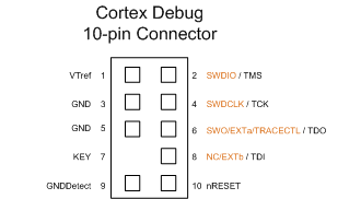
    Also, for nRF52 only three pins are required: SWDIO, SWDCLK, and VTref. All the three are very conveniently located in close proximity on pins 2, 4 and 1:

    CTX 10 pin

    Such, for a tiny custom board a 2x2 pin header, 1.27 pitch can be used w/o breaking compatibility.

    Hardware

  • 💬 rayBeacon: nRF52 on-the-go Development Kit
    M Mishka

    Well, looks like the CDEBYTE did great job by placing all required components. From the datasheet (yes, there is one, and that's awesome) I see the only missing part is 32.768kHz crystal which is not an issue either.

    The antenna is huge. If it was tuned properly it may give us up to +5dBi easily. Also, the 840 can be boosted up to +8dBm. IMHO this module looks like being serious about long range. I think you may get up to 1 km of it as is.

    Another good thing about the module is that it has easily accessible waveguide. Probably it may be possible to unmount the antenna, crop the board a little, and inject an RF front end (like SKY66405-11) to gain some +10dBm more. As I said, the antenna is good so it's worth to reuse it and save little bit more money. Tune it once and then call it a reference design. I don't know can someone make it to 5 km, but would be interesting to see the range.

    Anyhow, I've just spend $5 for my couple, thanks for the link! :-)

    Regarding the Raybeacon module - it was created as a tiny board for development on the go. I could take a Feather, but this one is smaller and has battery attached. Someone may also consider it as a reference design for own boards (as we in Raytrails do). Long range wasn't the goal here. I totally agree - employing a module is a good practice. Unfortunately, I just found no module with zero clearance for antenna so decided to go this way.

    OpenHardware.io raytrails nrf52 nrf52833 nrf52840 button cell

  • Everything nRF52840
    M Mishka

    @orhanyor AFAIU you're going to solder it manually, right? Will you use stencil or are you going to presoak pads? For the stencil it might be also reasonable to order a custom PCB pallet which may help to precisely align the board to the stencil. Similarly, another pallet may help to place the chip right into the center. It will be very interesting to hear from you how it went. Wish you best of luck!

    I've ordered some boards with nRF52840/nRF52833, but also had to ask for assembly for exactly this reason. The PCBWay did machine soldering of the aQFN chip, and the rest were soldered manually.

    By the way, the PCB price were raised two times: first, for 5 mil tolerance (the board uses NFC so I was unable to route antenna differently), and second, for ENIG finish because of the aQFN-73 package (the factory insisted on it in order to avoid soldering issues). I still have no room for the RESET, but perhaps I need to go your way and drop some unnecessary pins - that's nice idea.

    Hardware

  • 💬 rayBeacon: nRF52 on-the-go Development Kit
    M Mishka

    Hi,

    I'm very gald to post an update to the project. Revision 0.6 features fully round shape for the main board (and hence all extension boards). The battery placement is off-centric now, but it should fit just fine together with the extension socket. Please note, the dedicated ground pad has been also moved and now it's conveniently located right below the USB pads.

    OpenHardware.io raytrails nrf52 nrf52833 nrf52840 button cell

  • 💬 rayBeacon: nRF52 on-the-go Development Kit
    M Mishka

    And here is the revision 0.7.

    It adds 2x4 1.27 pitch pin header on the front side of the breadboard part. The connector is fully matches the Raybeacon extension socket - you may safely break the breadboard part off, and then solder a pin header there in order to use the detached piece as 1.27 to 2.54 adapter.

    With this change, need for a dedicated dock board is perhaps even less. If so, flip the SWD socket bottom up.

    OpenHardware.io raytrails nrf52 nrf52833 nrf52840 button cell

  • 💬 The Harvester: ultimate power supply for the Raybeacon DK
    M Mishka

    Hi @neverdie, thanks for your comment! Well, from what I've found in datasheets the SPV1050 was designed for ultra-low power apps and is very efficient in low light conditions, when SPV1040 is capable to gain up to 3W and its step-up converter is more suitable for outdoors. I've also considered bq25504 and LTC3103, but found that they seem isolate battery from the output where the load is expected to be. In contrast, the SPV1050 implements very simple approach by connecting the store and the battery via a FET - this allowed to connect main load parallel to the battery (where by fact it is) and disable integrated LDOs. Another advantage of the SPV1050 is that it's omnivorous - can accept input up to 18V (although I've configured it for 12V) and officially supports TEGs.

    But to be honest, never tried anything from the list so will eventually post my findings :-) So far the Raybeacon was finally assembled and sent to Nordic for tuning - you may have noticed updated pics on its page. So hope to advance the project status from preview to beta by the end of the year.

    OpenHardware.io raytrails solar mppt usb charger power supply teg

  • 💬 The Harvester: ultimate power supply for the Raybeacon DK
    M Mishka

    @NeverDie Just received the KXOB25-02X8F panels. In short - you was right, and I was too optimistic about indoor lights.

    Generally speaking, the pannel works really not bad and looks extremely handy. However, in order to achieve the desired 2.6V it has to be illuminated with greatly above 1000 lux which roughly equals bright supermarket or factory lights. And yes, it seem differentiates LED lamps from the sun.

    Accordingly to my (totally uncalibrated) luxmeter:

    • Living room room: 50 lx - 0.4 V
    • Overcast daylight, indoors: 250 lx - 1.4 V
    • Supermarket lights: 1300 - 2.0V
    • Overcast daylight, street: 2000 lx - 2.7V

    Therefore, it's safe to say that two of 02X8F would make it acceptably work in buck-boost configuration. By acceptable I mean it could charge an ML2032 battery, but batteryless operation is quite limited indeed.

    This pushes me to review use-cases for the Harvester. It has two input sources - first one is spv1050, and another one is MIC5205 3.2V LDO. I'm thinking about switching the spv1050 to boost configuration and cover only PV and TEG sources from 75 mV to 3.6V. At the same time LDO could handle sources capable to deliver 2.0V and above (2.0-3.2V with battery removed, and 3.2V to 16V with or without a battery). The point here is that at higher voltages there is likely a more capable source so MPPT might not be required.

    Such, although less flexible, one or two KXOB25-05X3F, 30mW each, and a "supercap" should be enough to power the nRF52 (and even an extra module) without the need of a battery. For more demanding applications, up to five KXOB25-14X1F could be used delivering 150mW in total. With 3.2V, 70mA limit on the spv1050 battery pin it sounds like a good match.

    Another option is to make the Harvester configurable via solder jumpers. This will put four more jumpers on top of it (and there are five on the back side already). Well, although possible, sounds too complicated as for one inch board.

    Any thoughts?

    P.S. I'm going to assembly a buck/boost board anyway so we can compare later.

    OpenHardware.io raytrails solar mppt usb charger power supply teg
  • Login

  • Don't have an account? Register

  • Login or register to search.
  • First post
    Last post
0
  • MySensors
  • OpenHardware.io
  • Categories
  • Recent
  • Tags
  • Popular