Sorry but do I understand correctly that relay should be visible as a Sensor in MyController?
Sorry but do I understand correctly that relay should be visible as a Sensor in MyController?
Of course it was issue on my side. My understanding was that GW baud rate in mycontroller should be baud rate of RS485. When I changed baud rate to correct value everything works well. Nod is added automatically.
But I would like to kindly ask you for next suggestion.
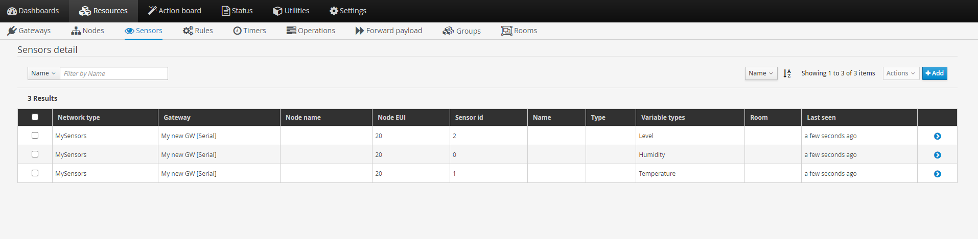
I plan to use one Arduino to monitor Temp, Hum and CO2. Those sensors are presented in MyController as static now.
Additionally script should control 3 relays. I added relay script from My sensors but I have no idea where I should see those relays in MyController and how to control them manually
// Enable debug prints to serial monitor
#define MY_DEBUG

// Enable RS485 transport layer
#define MY_RS485

// Define this to enables DE-pin management on defined pin
#define MY_RS485_DE_PIN 2

// Set RS485 baud rate to use
#define MY_RS485_BAUD_RATE 9600

// Enable this if RS485 is connected to a hardware serial port
//#define MY_RS485_HWSERIAL Serial1

#define MY_NODE_ID 20

#include <MySensors.h>

static const uint64_t UPDATE_INTERVAL = 10000;

#define CHILD_ID_HUM 0
#define CHILD_ID_TEMP 1
#define CHILD_ID_CO2 2

#define RELAY_PIN 10  // Arduino Digital I/O pin number for first relay (second on pin+1 etc)
#define NUMBER_OF_RELAYS 3 // Total number of attached relays
#define RELAY_ON 1  // GPIO value to write to turn on attached relay
#define RELAY_OFF 0 // GPIO value to write to turn off attached relay

MyMessage msgHum(CHILD_ID_HUM, V_HUM);
MyMessage msgTemp(CHILD_ID_TEMP, V_TEMP);
MyMessage msgCo2(CHILD_ID_CO2, V_LEVEL);
MyMessage msgCo2b(CHILD_ID_CO2, V_UNIT_PREFIX);

// ----------------------------------------------------------------------------

void before()
{
    for (int sensor=1, pin=RELAY_PIN; sensor<=NUMBER_OF_RELAYS; sensor++, pin++) {
        // Then set relay pins in output mode
        pinMode(pin, OUTPUT);
        // Set relay to last known state (using eeprom storage)
        digitalWrite(pin, loadState(sensor)?RELAY_ON:RELAY_OFF);
    }
}

void presentation()
{
  // Send the sketch version information to the gateway
  sendSketchInfo("Lihen", "1.0");

  // Register all sensors to gw (they will be created as child devices)
  present(CHILD_ID_HUM, S_HUM);
  present(CHILD_ID_TEMP, S_TEMP);
  present(CHILD_ID_CO2, S_AIR_QUALITY);
  send(msgCo2b.set("ppm"));

  for (int sensor=1, pin=RELAY_PIN; sensor<=NUMBER_OF_RELAYS; sensor++, pin++) {
    // Register all sensors to gw (they will be created as child devices)
    present(sensor, S_BINARY);
  }
}

// ----------------------------------------------------------------------------
void setup()
{
  Serial.println( F("Arduino MySensors RS485 Node test") );    // Fonction F() permet de placer la chaine dans la mémoire eprogramme (Arduino IDE 1.0).
  analogReference(INTERNAL);
  delay(1000);
}


void loop()
{
    Serial.println( F("Loop ...") );
    TempHum();
    readCO2();
    // Sleep for a while to save energy
    sleep(UPDATE_INTERVAL);
}

void TempHum ()
{
    int temperature = 30;
    int humidity = 50;
    Serial.print(F("Tmp: "));
    Serial.println(temperature);
    Serial.print(F("Hum: "));
    Serial.println(humidity);

    send(msgTemp.set(temperature, 1));
    send(msgHum.set(humidity, 1));
}

int readCO2()
{
    int CO2value = 1550;
    Serial.print(F("CO2: "));
    Serial.println(CO2value);

    send(msgCo2.set(CO2value));
}

void receive(const MyMessage &message)
{
    // We only expect one type of message from controller. But we better check anyway.
    if (message.getType()==V_STATUS) {
        // Change relay state
        digitalWrite(message.getSensor()-1+RELAY_PIN, message.getBool()?RELAY_ON:RELAY_OFF);
        // Store state in eeprom
        saveState(message.getSensor(), message.getBool());
        // Write some debug info
        Serial.print("Incoming change for sensor:");
        Serial.print(message.getSensor());
        Serial.print(", New status: ");
        Serial.println(message.getBool());
    }
}
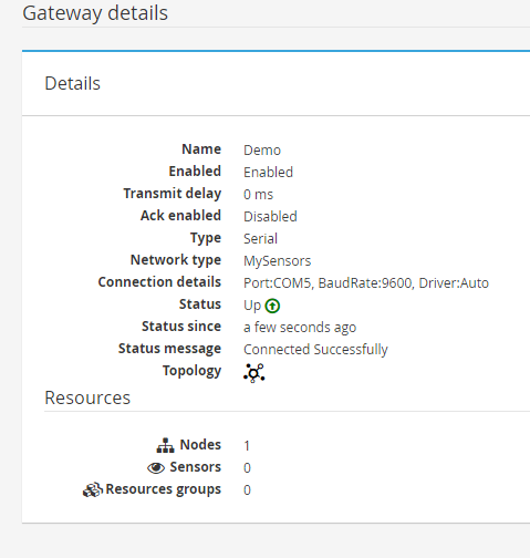
Gateway
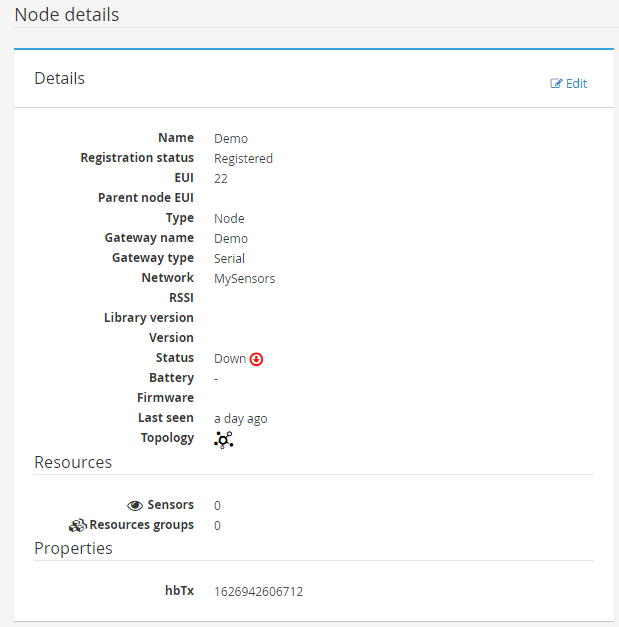
Node
Unfortunately function discover does not add anything
Hello,
I would like to ask you for your help. I frozen on adding a Nodes to Mycontroller.
I am using Serial RS485 gateway - This I managed to add to MyController

As a Nod I am using DHT sketch with RS485 enabled and NOD definition
#define MY_NODE_ID 22
#define MY_PARENT_NODE_ID 0
If I try to add Node manually Node is in status down

Communication between GW and Node works well
0;255;3;0;9;0 MCO:BGN:INIT GW,CP=RSNGA---,FQ=16,REL=255,VER=2.3.2
0;255;3;0;9;5 TSM:INIT
0;255;3;0;9;7 TSF:WUR:MS=0
0;255;3;0;9;10 TSM:INIT:TSP OK
0;255;3;0;9;13 TSM:INIT:GW MODE
0;255;3;0;9;15 TSM:READY:ID=0,PAR=0,DIS=0
0;255;3;0;9;19 MCO:REG:NOT NEEDED
0;255;3;0;14;Gateway startup complete.
0;255;0;0;18;2.3.2
0;255;3;0;9;23 MCO:BGN:STP
0;255;3;0;9;29 MCO:BGN:INIT OK,TSP=1
0;255;3;0;9;33 TSM:READY:NWD REQ
0;255;3;0;9;53 ?TSF:MSG:SEND,0-0-255-255,s=255,c=3,t=20,pt=0,l=0,sg=0,ft=0,st=OK:
0;255;3;0;9;7954 TSF:MSG:READ,22-22-0,s=0,c=1,t=1,pt=7,l=5,sg=0:41.0
22;0;1;0;1;41.0
Thank you very much for any advice
This solved my issue!! Thank you!!
Hi,
I have the same issue.
I used example library and upload Serial Gateway RS485 and Motion Sensor RS485. Both to Arduino UNO. Wiring according to (https://forum.mysensors.org/assets/uploads/files/1585670689122-example-rs485-mqtt.p)
Gateway Log
0;255;3;0;9;0 MCO:BGN:INIT GW,CP=RSNGA---,FQ=16,REL=255,VER=2.3.2
0;255;3;0;9;5 TSM:INIT
0;255;3;0;9;7 TSF:WUR:MS=0
0;255;3;0;9;10 TSM:INIT:TSP OK
0;255;3;0;9;13 TSM:INIT:GW MODE
0;255;3;0;9;15 TSM:READY:ID=0,PAR=0,DIS=0
0;255;3;0;9;19 MCO:REG:NOT NEEDED
0;255;3;0;14;Gateway startup complete.
0;255;0;0;18;2.3.2
0;255;3;0;9;23 MCO:BGN:STP
0;255;3;0;9;29 MCO:BGN:INIT OK,TSP=1
0;255;3;0;9;33 TSM:READY:NWD REQ
0;255;3;0;9;53 ?TSF:MSG:SEND,0-0-255-255,s=255,c=3,t=20,pt=0,l=0,sg=0,ft=0,st=OK:
NOD Log
16 MCO:BGN:INIT NODE,CP=RSNNA---,FQ=16,REL=255,VER=2.3.2
26 TSM:INIT
28 TSF:WUR:MS=0
29 TSM:INIT:TSP OK
31 TSF:SID:OK,ID=123
32 TSM:FPAR
51 ?TSF:MSG:SEND,123-123-255-255,s=255,c=3,t=7,pt=0,l=0,sg=0,ft=0,st=OK:
2059 !TSM:FPAR:NO REPLY
2061 TSM:FPAR
2078 ?TSF:MSG:SEND,123-123-255-255,s=255,c=3,t=7,pt=0,l=0,sg=0,ft=0,st=OK:
4086 !TSM:FPAR:NO REPLY
4088 TSM:FPAR
4106 ?TSF:MSG:SEND,123-123-255-255,s=255,c=3,t=7,pt=0,l=0,sg=0,ft=0,st=OK:
6114 !TSM:FPAR:NO REPLY
6116 TSM:FPAR
6133 ?TSF:MSG:SEND,123-123-255-255,s=255,c=3,t=7,pt=0,l=0,sg=0,ft=0,st=OK:
8141 !TSM:FPAR:FAIL
8142 TSM:FAIL:CNT=1
8144 TSM:FAIL:DIS
8146 TSF:TDI:TSL
18148 TSM:FAIL:RE-INIT
18150 TSM:INIT
18151 TSM:INIT:TSP OK
18153 TSF:SID:OK,ID=123
18155 TSM:FPAR
18173 ?TSF:MSG:SEND,123-123-255-255,s=255,c=3,t=7,pt=0,l=0,sg=0,ft=0,st=OK:
20182 !TSM:FPAR:NO REPLY
Try with NODE ID definition or without
#define MY_PARENT_NODE_ID 0
Thnak you for any help!!
I found an root cause.
In pin definition was
#define AIQ_SENSOR_ANALOG_PIN 1
but should be
#define AIQ_SENSOR_ANALOG_PIN A1
I do not know why with first definition it worked with nano but did not work with mini.
@rejoe2 said in MQ135 with RS485:
NodeID
Hmm, I tried to define sensor as 30 but still the same result. In log of sensor I can see
114875 !TSM:FPAR:NO REPLY
114877 TSM:FPAR
114895 TSF:MSG:SEND,30-30-255-255,s=255,c=3,t=7,pt=0,l=0,sg=0,ft=0,st=OK:
I think that it is not a case. As I told everything works with arduino nano.
How I can check if data from sensor are reading?
It seems that code does not continue if sensor is not connected to gateway.
Now I replaced mini pro and used nano instead. Data were send successfully.
Do you have any idea what can be wrong with mini pro?
Hello,
I try to get working my MQ135 on RS485 but I cannot manage to make it working.
I use UNO as Gateway + 2 separate sensors (DHT on UNO and MQ135 on pro mini 5V)
DHT works correctly but MQ135 does not work.
For testing purpose I disconnected DHT.
I wanted to be sure that MQ135 is connected correctly so I uploaded another code and everything works correctly, But with code below I cannot send data to gateway. I used as a source of code following MySensor forum code
Connection
MQ135 - arduino pro mini 5V
Vcc - Vcc 5V
GND - GND
AO - A1
RS485 - arduino pro mini 5V
DI - D9
R0 - D8
DE/RE - D2
GND - GND
Vcc - Vcc 5V
A - A(gateway RS485)
A - A(gateway RS485)
CODE
/*
  Arduino MQ135
  connect the sensor as follows :
  A H A   >>> 5V
  B       >>> A0
  H       >>> GND
  B       >>> 10K ohm >>> GND

  Contribution: epierre
  Based on David Gironi http://davidegironi.blogspot.fr/2014/01/cheap-co2-meter-using-mq135-sensor-with.html
  http://skylink.dl.sourceforge.net/project/davidegironi/avr-lib/avr_lib_mq135_01.zip

*/

// Enable debug prints
#define MY_DEBUG


// Enable RS485 transport layer
#define MY_RS485

// Define this to enables DE-pin management on defined pin
#define MY_RS485_DE_PIN 2

// Set RS485 baud rate to use
#define MY_RS485_BAUD_RATE 9600

// Enable this if RS485 is connected to a hardware serial port
//#define MY_RS485_HWSERIAL Serial1

// #include <SPI.h>
//#include <MySensor.h>
#include <MySensors.h>
#include <Wire.h>

#define CHILD_ID_AIQ 0
#define AIQ_SENSOR_ANALOG_PIN 1

#define MQ135_DEFAULTPPM 399 //default ppm of CO2 for calibration
#define MQ135_DEFAULTRO 68550 //default Ro for MQ135_DEFAULTPPM ppm of CO2
#define MQ135_SCALINGFACTOR 116.6020682 //CO2 gas value
#define MQ135_EXPONENT -2.769034857 //CO2 gas value
#define MQ135_MAXRSRO 2.428 //for CO2
#define MQ135_MINRSRO 0.358 //for CO2

unsigned long SLEEP_TIME = 30000; // Sleep time between reads (in seconds)
//VARIABLES
float mq135_ro = 10000.0;    // this has to be tuned 10K Ohm
int val = 0;                 // variable to store the value coming from the sensor
float valAIQ =0.0;
float lastAIQ =0.0;

// MySensor gw;
MyMessage msg(CHILD_ID_AIQ, V_LEVEL);

void setup()
{
//  gw.begin();

  // Send the sketch version information to the gateway and Controller
 // gw.sendSketchInfo("AIQ Sensor MQ135", "1.0");

  // Register all sensors to gateway (they will be created as child devices)
//  gw.present(CHILD_ID_AIQ, S_AIR_QUALITY);

}

void presentation()
{
  // Send the sketch version information to the gateway and Controller
  sendSketchInfo("AIQ Sensor MQ135", "1.0");

  // Register all sensors to gw (they will be created as child devices)
  present(CHILD_ID_AIQ, S_AIR_QUALITY);
}

/*
 * get the calibrated ro based upon read resistance, and a know ppm
 */
long mq135_getro(long resvalue, double ppm) {
return (long)(resvalue * exp( log(MQ135_SCALINGFACTOR/ppm) / MQ135_EXPONENT ));
}

/*
 * get the ppm concentration
 */
double mq135_getppm(long resvalue, long ro) {
double ret = 0;
double validinterval = 0;
validinterval = resvalue/(double)ro;
if(validinterval<MQ135_MAXRSRO && validinterval>MQ135_MINRSRO) {
ret = (double)MQ135_SCALINGFACTOR * pow( ((double)resvalue/ro), MQ135_EXPONENT);
}
return ret;
}

void loop()
{
  uint16_t valr = analogRead(AIQ_SENSOR_ANALOG_PIN);// Get AIQ value
  Serial.println(val);
  uint16_t val =  ((float)22000*(1023-valr)/valr);
  //during clean air calibration, read the Ro value and replace MQ135_DEFAULTRO value with it, you can even deactivate following function call.
  mq135_ro = mq135_getro(val, MQ135_DEFAULTPPM);
  //convert to ppm (using default ro)
  valAIQ = mq135_getppm(val, MQ135_DEFAULTRO);

  Serial.print ( "Val / Ro / value:");
  Serial.print ( val);
  Serial.print ( " / ");
  Serial.print ( mq135_ro);
  Serial.print ( " / ");
  Serial.print ( valAIQ);


  if (valAIQ != lastAIQ) {
    //  gw.send(msg.set(MQ135_DEFAULTPPM+(int)ceil(valAIQ)));
       send(msg.set(MQ135_DEFAULTPPM+(int)ceil(valAIQ)));
      lastAIQ = ceil(valAIQ);
  }

  // Power down the radio.  Note that the radio will get powered back up
  // on the next write() call.
  //gw.sleep(SLEEP_TIME); //sleep for: sleepTime
  sleep(SLEEP_TIME); //sleep for: sleepTime
}


/*****************************  MQGetPercentage **********************************
Input:   rs_ro_ratio - Rs divided by Ro
         pcurve      - pointer to the curve of the target gas
Output:  ppm of the target gas
Remarks: By using the slope and a point of the line. The x(logarithmic value of ppm)
         of the line could be derived if y(rs_ro_ratio) is provided. As it is a
         logarithmic coordinate, power of 10 is used to convert the result to non-logarithmic
         value.
************************************************************************************/
int  MQGetPercentage(float rs_ro_ratio, float ro, float *pcurve)
{
  return (double)(pcurve[0] * pow(((double)rs_ro_ratio/ro), pcurve[1]));
}
SENSOR LOG
16 MCO:BGN:INIT NODE,CP=RSNNA---,REL=255,VER=2.3.1
26 TSM:INIT
27 TSF:WUR:MS=0
28 TSM:INIT:TSP OK
30 TSM:FPAR
49 TSF:MSG:SEND,255-255-255-255,s=255,c=3,t=7,pt=0,l=0,sg=0,ft=0,st=OK:
2056 !TSM:FPAR:NO REPLY
2058 TSM:FPAR
2075 TSF:MSG:SEND,255-255-255-255,s=255,c=3,t=7,pt=0,l=0,sg=0,ft=0,st=OK:
4083 !TSM:FPAR:NO REPLY
4085 TSM:FPAR
4103 TSF:MSG:SEND,255-255-255-255,s=255,c=3,t=7,pt=0,l=0,sg=0,ft=0,st=OK:
6111 !TSM:FPAR:NO REPLY
6113 TSM:FPAR
6130 TSF:MSG:SEND,255-255-255-255,s=255,c=3,t=7,pt=0,l=0,sg=0,ft=0,st=OK:
8138 !TSM:FPAR:FAIL
8139 TSM:FAIL:CNT=1
8141 TSM:FAIL:DIS
8143 TSF:TDI:TSL
GATEWAY LOG
0;255;3;0;9;0 MCO:BGN:INIT GW,CP=RSNGA---,REL=255,VER=2.3.1
0;255;3;0;9;5 TSM:INIT
0;255;3;0;9;7 TSF:WUR:MS=0
0;255;3;0;9;9 TSM:INIT:TSP OK
0;255;3;0;9;12 TSM:INIT:GW MODE
0;255;3;0;9;15 TSM:READY:ID=0,PAR=0,DIS=0
0;255;3;0;9;18 MCO:REG:NOT NEEDED
0;255;3;0;14;Gateway startup complete.
0;255;0;0;18;2.3.1
0;255;3;0;9;23 MCO:BGN:STP
0;255;3;0;9;29 MCO:BGN:INIT OK,TSP=1
0;255;3;0;9;32 TSM:READY:NWD REQ
0;255;3;0;9;52 TSF:MSG:SEND,0-0-255-255,s=255,c=3,t=20,pt=0,l=0,sg=0,ft=0,st=OK:
Thank you very much for any help!!!
Thank you very much for great explanation!!!
But is there a way how to connect ESP8266 to Controller. In MySensors are available just ethernet or serial gateway with NRF. Of course I can connect ESP to NRF and then use serial gateway but then there is no difference if I use ESP or nano.
My idea is that I want to use wireless network for sensors. One of my sensor should be LCD/TFT with touch so I wanted to prevent to use NRF (it occuy SPI)
https://forum.mysensors.org/topic/9276/home-automation-tft-touch-display
Hello,
Maybe I have a stupid question but I did not find proper information on this forum or internet.
Currently I use serial gateway (Uno + NRF24 connected via USB, MyController) for connection of sensors. So sensors are arduinos (uno, mini, ...) with sensor and NRF24.
And now my stupid question. Can I connect WeMos D1 mini directly to my gateway (without NRF24)? Both items works on 2.4GHz.
Thank you for your reply
Hello,
I would like to promote my home automation system and be able to control room settings for each room.
I use MySensors + MyController.
In rooms I measure Temperature, Humidity, AirQuality, and I control air condition, heating and electronic window blind.
I would like to have a TFT touch display in each room with possibility to see all measured values and (on button click or slide) + be able to control temperature (thermostat), open or close window blind.
Additionally i would like to build it small .. not like on mega but on nano. Unfortunatley NRF and TFT use MISO/MOSI so I need to use custom pins for TFT.
Do you know if it is doable and could you recommend solution/concept?
Thank you very much!