@รอเร-อ btw Normal single phase type 2 charging on an EV is 32a = 7 Kw. If your ev can charge at 22Kw, then it will need a 3 phase supply. OpenEVSE can do this but you will need to put a 3 phase contactor in it.
R
rmh
Posts
-
EV Charger (type 2) with RESTful API and Wifi recommendations? -
EV Charger (type 2) with RESTful API and Wifi recommendations?@รอเร-อ take a look at openevse https://shop.openenergymonitor.com/openevse-wifi-emoncms-ev-charging-station-diy-kit/
Just got one, delivered in a couple of days from UK - 'deluxe' version with ESP8266 is fully controllable via mqtt or built-in app. Assembly instructions aren't great. Our EV not arrived yet so I can't tell you if it works - I expect it will.
R
-
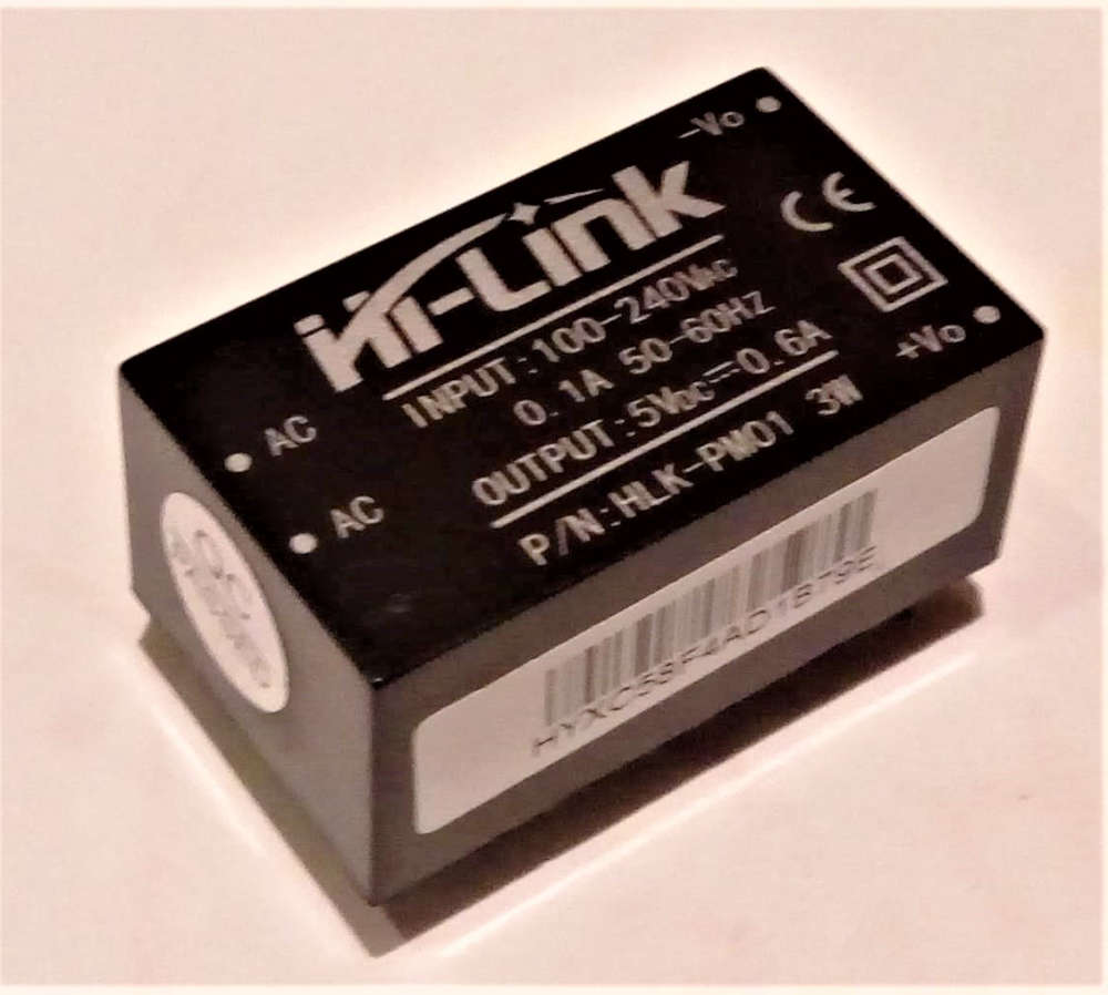
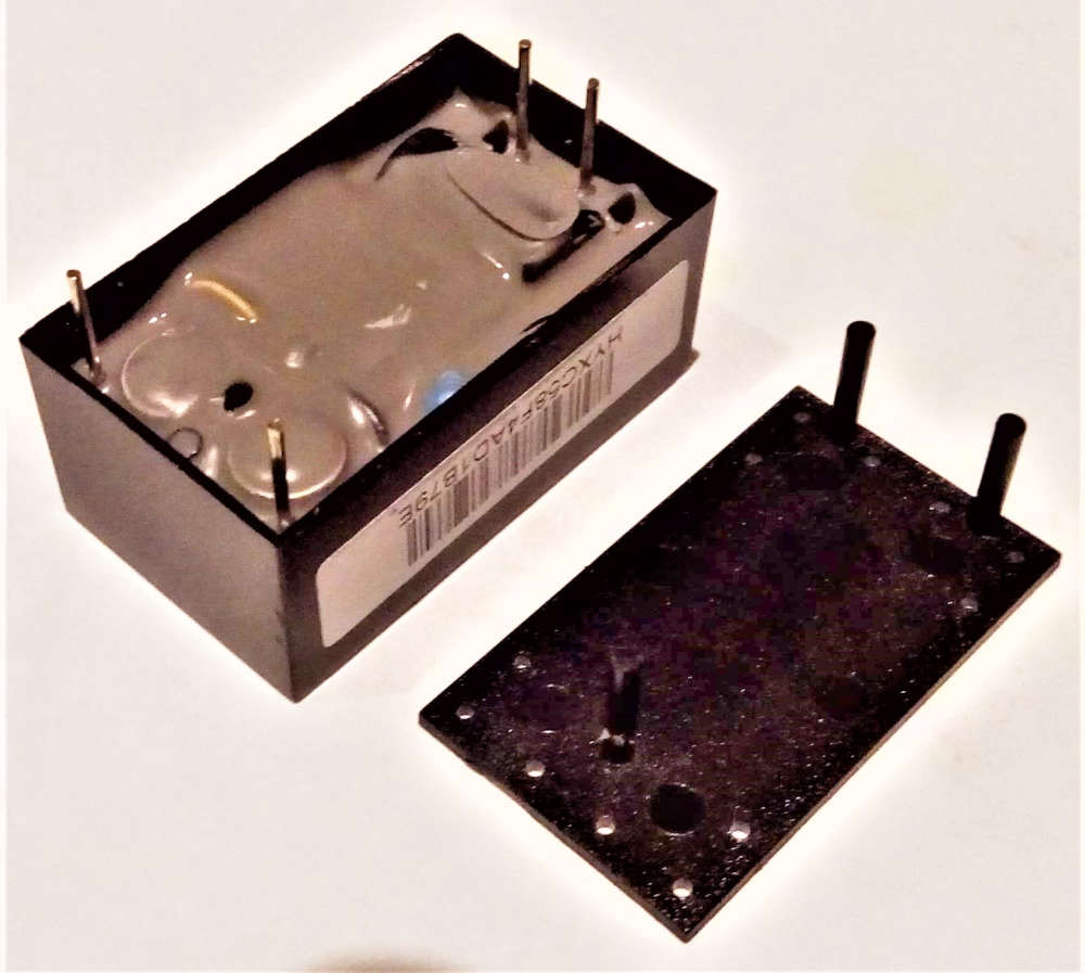
Safe In-Wall AC to DC Transformers??Received some hilink transformers today from QIMEI Electronics Network Technology Co., Ltd in China; Compared to the posts above, the 3.3v ones look genuine, but not sure about the 5v ones.
The side the pins come out of does not have the central hole and feels 'squigy' so I lifted it off one of them and the space inside is not completely filled with the encapsulation stuff, but it does feel slightly rubbery like the real ones...
Maybe a new variant of the real thing? Or fake?
These are destined for being outside in waterproof boxes, so I'll let you know if any catch fire....
Richard
(


-
Blink on nodeMCU / RFM69 gatewayMy gateway works fine with the vanilla wiring as per RFM69/95 & ESP8266 at https://www.mysensors.org/build/connect_radio and the example GatewayESP8266MQTTClient sketch.
I have tried adding the Radio Traffic LEDs as per https://www.mysensors.org/build/advanced_gateway but whichever available pins I use:
D2 / D3 / D4 : leds blink but comms to nodes seem to fail with NOACK
D9 / D10 : seems to work but lose serial output for debug.I expect someone has made this work before - what am I doing wrong?
Thanks
Richard
-
sleep mode not working as expected...@mfalkvidd thanks for the welcome and your prompt reply.
The log is always showing
2101803 MCO:SLP:WUP=-1 Node woke-up, reason/IRQ=-1 (-2=not possible, -1=timer, >=0 IRQ)So it would appear the 'timer' is doing the waking as I would expect, but since the millis timer is frozen in sleep mode, what timer is this? I kind of imagine it is firing interrupt 1 (pin 3) to wake it up, but my use of the same pin for the counter is interfering with this somehow?
Thanks
Richard
-
sleep mode not working as expected...Hi all
I have a solar powered node counting pulses on a water meter. Hardware is a ceech board (=pro-mini) which takes care of pv and charging, a RFM69 radio, and a RC+schmitt inverter circuit to do hardware debounce.
Sketch is a cut down and modified version of the WaterMeterPulseSensor example with flow removed because I have SLEEP_MODE true
According to the standard wiring diagram, the D100 pin of the RFM69 radio goes to pin 2 of the arduino, so I've set the other interrupt pin 3 for the pulse counting #define DIGITAL_INPUT_SENSOR 3
And it all works as expected - Except:
If there is no pulse during the sleep period then it sleeps more-or-less the time I expect, however, if there are pulses, (which it seems to be counting correctly), it seems to wake up at approx 20 sec intervals, totally ignoring whatever I put as the sleep period, eg sleep(90000); or smartSleep(90000);
This leads me to think there's something going on with my interrupts which is waking it unexpectedly, but because I don't really understand how the mySensors sleep thing works I have no idea how to fix it....
Thanks
Richard
