Navigation

    • Register
    • Login
    • OpenHardware.io
    • Categories
    • Recent
    • Tags
    • Popular
    1. Home
    2. rolandow
    3. Posts
    • Profile
    • Following
    • Followers
    • Topics
    • Posts
    • Best
    • Groups

    Posts made by rolandow

    • RE: 💬 MySensors InCan double light switch

      I haven't started on my project yet, so I am glad to read some more information here.

      @stormy: could you please add a bit of documentation and/or links to (english) documentation about how to put the bootloader on the atmel? Personally I haven't done this before; my Arduino's already had the right bootloader. I would like to know what the recommended uploader would be (maybe with a link or picture?) and what the recommended procedure would be to upload this.

      Thanks for opening my eyes about this @magpern 🙂

      posted in OpenHardware.io
      rolandow
      rolandow
    • RE: 💬 Building a Raspberry Pi Gateway
      1. For me, my electronics is not as good as my development skills ;-). But I gave it a try. According to the datasheet the NRF24 will consume about 14 mA max. My cable is 2 m max, so then the resistance is 0,16ohms. So if I understand correctly the voltage drop would be 0,00224 volt. Sounds neglegtable to me? Also; can't I just measure the voltage at the end of the cable once it's connected to the RPI?

      2. At the stackoverflow page somebody says: "In an answer on a Microchip forum, Jan Axelson, author of 'Serial Port Complete', claims a maximum cable length of 10' for the SPI bus. Other posts have mentioned the same figure.". So 10" is about 3 metres, so I am within that range. I do understand though that this isn't a preferred thing to do.

      Which makes me wonder how other people handle this. I mean; I think ideally you'd want the radio that is connected to the controller in the most 'center' way of the home, right? So do people just hange the Pi and the whole shebang to the ceiling? 😉 I'd rather put the controller in the closet where my modem and router are, and then only wire the receiver to outside the closet. Isn't there a better way to do this?

      posted in Announcements
      rolandow
      rolandow
    • RE: 💬 MySensors InCan double light switch

      Thank you for your reply. I did rename the files, and then I could view the design. I do understand now why the other drill file wasn't selected. I ordered 10 pieces and am very excited about it.

      Another thing I was wondering; could I leave out 1 relay if I only need one? I only have single switches at the moment. Even if I'd install double switches, the second switch would probably be a 'virtual' switch that isn't connected to a relay anyways.

      Great project!

      posted in OpenHardware.io
      rolandow
      rolandow
    • RE: 💬 Building a Raspberry Pi Gateway

      Ok, one more question. I thought I read somewhere that the wiring between the RPI and de radio should be as short as possible, but I can't find exactly where I read that anymore.

      At another project (zigbee2mqtt) I read that users had better reception when they placed the transceiver further away from the controller, because there was less inteference. So if possible, I would like to use a piece of UTP cable to wire the radio to the raspberry pi. That way I can put the rpi inside a closet, but the radio outside.

      So I am not sure if longer wires (say 2, 3 meters) is going to be a problem?

      posted in Announcements
      rolandow
      rolandow
    • RE: 💬 Building a Raspberry Pi Gateway

      @marceloaqno Sorry to kick this old topic, but I will soon be trying to build my gateway with a Raspberry pi. I was wondering if the capacitor is also required for the gateway, or just for the nodes?

      Because at the instruction page on how to wire and build a Raspberry Pi gateway, the capacitor isn't mentioned.

      I'll be using a RPI 1 and NRF24L01+

      posted in Announcements
      rolandow
      rolandow
    • RE: 💬 MySensors InCan double light switch

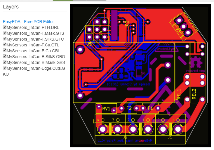
      I think I am one step further now. For Seeed Studio, I renamed the files (see below). I am not sure though about the "edge cuts". But when I check the viewer in Seeed Studio, I guess the PCB looks okay, except that I am missing one DRL file. The -NPTH.DRL is not used for the design. Is this normal?

      I renamed the files to this:

      MySensors_InCan-B.Cu.GBL
      MySensors_InCan-B.Mask.GBS
      MySensors_InCan-B.SilkS.GBO
      MySensors_InCan-Edge.Cuts.GKO
      MySensors_InCan-F.Cu.GTL
      MySensors_InCan-F.Mask.GTS
      MySensors_InCan-F.SilkS.GTO
      MySensors_InCan-NPTH.DRL
      MySensors_InCan-PTH.DRL

      Gerber viewer looks like this:

      alt text

      So where is MySensors_InCan-NPTH.DRL ??

      posted in OpenHardware.io
      rolandow
      rolandow
    • RE: 💬 MySensors InCan double light switch

      I would really want to try and build this, but I don't have a clue how to get started. I'm not afraid to solder the pieces to the board, but I have never ordered a board before. Where should I go, and what files do I need?

      I check pcbaway, but the site is pretty overwhelming for me 🙂

      posted in OpenHardware.io
      rolandow
      rolandow
    • RE: 💬 Sensebender Gateway

      Forgive me if this isn't the right place to ask; but as a beginner, where do I start? How can I order this thing, or any other stuff from OpenHardware.io ? I see so many design files, I'm not sure what to do with them. Soldering the thing I can probably manage, but is there a guide available how to order the PCB, and maybe the parts as well?

      posted in OpenHardware.io
      rolandow
      rolandow
    • RE: New compile error for Pro Mini 3.3v 168

      I am aware of the open source concept, I wasn't trying to push something or somebody ;-). It just surprised me a bit that this issue comes up in a newer version of the library.

      I was wondering; how can I easily switch to a lower version of MySensors? Are you using the Arduino IDE to do so? I read some github issues about maintaining libraries with different versions, and it seems to be rather complicated or unsupported even. So what is the recommended way if I want to use version 2.1.1.

      Maybe I can already test my communication while I'm waiting for my logic level shifters to arrive.

      posted in Bug Reports
      rolandow
      rolandow
    • RE: New compile error for Pro Mini 3.3v 168

      @mfalkvidd Ok, no problem. So if I understand correctly, a bug appeared in the newer MySensors lib, so this would probably be fixed in the future, because of the issue that was opened on github?

      I will switch to the atmega 328 for my current. When I was even more a rookie than I am now, I didn't pay any attention to the chips that was on the pro mini. So now I have a bunch of those atmega168's. Maybe I could still use them as a door sensor. I imagine this shouldn't take too much extra memory.

      posted in Bug Reports
      rolandow
      rolandow
    • RE: New compile error for Pro Mini 3.3v 168

      @mfalkvidd Thank you for trying to compile my code :-). I am wondering how I can use the 2.2.1 version of MySensors though, because on github I can't find it anywhere. I cannot find a tag with 2.2.1 and develop and master have different versions as well.

      posted in Bug Reports
      rolandow
      rolandow
    • New compile error for Pro Mini 3.3v 168

      Re: [Compile error for Pro Mini 5](5v 168)

      I read about compile errors earlier, and that the 168 chip wasn't supported. But I believe some fixes has been done, so now it should be supported right?

      So I am trying to create a node with this pro mini 3.3v. I connected a RFM69hw to it. Then I copied the button sketch, just for testing to see if I could make this work. I deleted the Bouncer and SPI module to make sure that this wasn't the reason for the compile error.

      The compile error is:

      Arduino: 1.8.1 (Windows 7), Board: "Arduino Pro or Pro Mini, ATmega168 (3.3V, 8 MHz)"
      
      Build options changed, rebuilding all
      In file included from c:\users\r.od.akker\appdata\local\arduino15\packages\arduino\tools\avr-gcc\4.9.2-atmel3.5.4-arduino2\avr\include\avr\io.h:99:0,
      
                       from c:\users\r.od.akker\appdata\local\arduino15\packages\arduino\tools\avr-gcc\4.9.2-atmel3.5.4-arduino2\avr\include\avr\pgmspace.h:90,
      
                       from C:\Users\r.od.akker\AppData\Local\Arduino15\packages\arduino\hardware\avr\1.6.21\cores\arduino/Arduino.h:28,
      
                       from sketch\MySensorsButton.ino.cpp:1:
      
      C:\Roland\Arduino\libraries\MySensors/hal/architecture/AVR/MyHwAVR.cpp: In function 'bool hwUniqueID(uint8_t (*)[16])':
      
      C:\Roland\Arduino\libraries\MySensors/hal/architecture/AVR/MyHwAVR.cpp:246:26: error: 'SIGRD' was not declared in this scope
      
        *((uint8_t*)uniqueID) = boot_signature_byte_get(0x00);
      
                                ^
      
      C:\Roland\Arduino\libraries\MySensors/hal/architecture/AVR/MyHwAVR.cpp:247:30: error: 'SIGRD' was not declared in this scope
      
        *((uint8_t*)uniqueID + 1) = boot_signature_byte_get(0x02);
      
                                    ^
      
      C:\Roland\Arduino\libraries\MySensors/hal/architecture/AVR/MyHwAVR.cpp:248:30: error: 'SIGRD' was not declared in this scope
      
        *((uint8_t*)uniqueID + 2) = boot_signature_byte_get(0x04);
      
                                    ^
      
      C:\Roland\Arduino\libraries\MySensors/hal/architecture/AVR/MyHwAVR.cpp:249:30: error: 'SIGRD' was not declared in this scope
      
        *((uint8_t*)uniqueID + 3) = boot_signature_byte_get(0x01); //OSCCAL
      
                                    ^
      
      exit status 1
      Error compiling for board Arduino Pro or Pro Mini.
      
      This report would have more information with
      "Show verbose output during compilation"
      option enabled in File -> Preferences.
      

      And just to be complete, my sketch is:

      /**
       * The MySensors Arduino library handles the wireless radio link and protocol
       * between your home built sensors/actuators and HA controller of choice.
       * The sensors forms a self healing radio network with optional repeaters. Each
       * repeater and gateway builds a routing tables in EEPROM which keeps track of the
       * network topology allowing messages to be routed to nodes.
       *
       * Created by Henrik Ekblad <henrik.ekblad@mysensors.org>
       * Copyright (C) 2013-2015 Sensnology AB
       * Full contributor list: https://github.com/mysensors/Arduino/graphs/contributors
       *
       * Documentation: http://www.mysensors.org
       * Support Forum: http://forum.mysensors.org
       *
       * This program is free software; you can redistribute it and/or
       * modify it under the terms of the GNU General Public License
       * version 2 as published by the Free Software Foundation.
       *
       *******************************
       *
       * DESCRIPTION
       *
       * Simple binary switch example 
       * Connect button or door/window reed switch between 
       * digitial I/O pin 3 (BUTTON_PIN below) and GND.
       * http://www.mysensors.org/build/binary
       */
      
      
      // Enable debug prints to serial monitor
      #define MY_DEBUG 
      
      // Enable and select radio type attached
      //#define MY_RADIO_NRF24
      #define MY_RADIO_RFM69
      #define MY_IS_RFM69HW
      //#define MY_RFM69_FREQUENCY RFM69_868MHZ
      
      #include <MySensors.h>
      
      #define CHILD_ID 3
      #define BUTTON_PIN  3  // Arduino Digital I/O pin for button/reed switch
      
      int oldValue=-1;
      
      // Change to V_LIGHT if you use S_LIGHT in presentation below
      MyMessage msg(CHILD_ID,V_TRIPPED);
      
      void setup()  
      {  
        // Setup the button
        pinMode(BUTTON_PIN,INPUT);
        // Activate internal pull-up
        digitalWrite(BUTTON_PIN,HIGH);
        
      }
      
      void presentation() {
        // Register binary input sensor to gw (they will be created as child devices)
        // You can use S_DOOR, S_MOTION or S_LIGHT here depending on your usage. 
        // If S_LIGHT is used, remember to update variable type you send in. See "msg" above.
        present(CHILD_ID, S_DOOR);  
      }
      
      
      //  Check if digital input has changed and send in new value
      void loop() 
      {
        int value = digitalRead(BUTTON_PIN);
       
        if (value != oldValue) {
           // Send in the new value
           send(msg.set(value==HIGH ? 1 : 0));
           oldValue = value;
        }
      } 
      

      Does this mean the atmel 168 isn't supported enough yet? MySensors lib is up to date at 2.2.0.

      posted in Bug Reports
      rolandow
      rolandow
    • Node can't find parent; what am I missing here?

      Hi! After a long time of following mysensors I finally build my own setup, but I am stuck already. To prevent TL;DR: the node and gateway seem to work fine, according to the serial logs. But the gw and node just don't seem to 'see' each other.

      As controller I am using Home Assistant, although at first I started without the controller. I was expecting to see some incoming messages at the gateway when it's in debug mode, but that didn't work, so then I thought maybe the controller is already needed.

      As a gateway I used a Raspberry Pi 1 with .configure options: --my-transport=rfm69 --my-rfm69-frequency=868 --my-is-rfm69hw --my-gateway=ethernet --my-port-5003. This build fine and runs fine. When I start the gateway in debug mode I get this:

      mysgw: Starting gateway...
      mysgw: Protocol version - 2.3.0-alpha
      mysgw: MCO:BGN:INIT GW,CP=RPNGL---,VER=2.3.0-alpha
      mysgw: TSF:LRT:OK
      mysgw: TSM:INIT
      mysgw: TSF:WUR:MS=0
      mysgw: TSM:INIT:TSP OK
      mysgw: TSM:INIT:GW MODE
      mysgw: TSM:READY:ID=0,PAR=0,DIS=0
      mysgw: MCO:REG:NOT NEEDED
      mysgw: Listening for connections on 0.0.0.0:5003
      mysgw: MCO:BGN:STP
      mysgw: MCO:BGN:INIT OK,TSP=1
      mysgw: New connection from 192.168.1.202
      mysgw: GWT:TSA:C=0,CONNECTED
      mysgw: GWT:TSA:C=0,DISCONNECTED
      mysgw: Ethernet client disconnected.
      mysgw: New connection from 192.168.1.202
      mysgw: GWT:TSA:C=0,CONNECTED
      mysgw: GWT:RFC:C=0,MSG=0;255;3;0;2;
      mysgw: GWT:RFC:C=0,MSG=0;255;3;0;2;
      

      So in my opinion the gateway works fine, or at least no error messages.

      For the node I use the MySensorButton example on an Arduino Uno. I connected the radio to the 3.3v pin and I connected a 5V3A power supply as well as the USB cable (to be able to use the monitor). I think that should be enough power? I added defines for the rfm69 to the sketch like this:

      #define MY_RADIO_RFM69
      #define MY_IS_RFM69HW
      

      The serial monitor looks like this:

      16 MCO:BGN:INIT NODE,CP=RRNNA---,VER=2.2.0
      25 TSM:INIT
      26 TSF:WUR:MS=0
      29 TSM:INIT:TSP OK
      30 TSM:FPAR
      1250 TSF:MSG:SEND,255-255-255-255,s=255,c=3,t=7,pt=0,l=0,sg=0,ft=0,st=OK:
      3257 !TSM:FPAR:NO REPLY
      3259 TSM:FPAR
      4480 TSF:MSG:SEND,255-255-255-255,s=255,c=3,t=7,pt=0,l=0,sg=0,ft=0,st=OK:
      6487 !TSM:FPAR:NO REPLY
      6489 TSM:FPAR
      7708 TSF:MSG:SEND,255-255-255-255,s=255,c=3,t=7,pt=0,l=0,sg=0,ft=0,st=OK:
      9715 !TSM:FPAR:NO REPLY
      9717 TSM:FPAR
      10936 TSF:MSG:SEND,255-255-255-255,s=255,c=3,t=7,pt=0,l=0,sg=0,ft=0,st=OK:
      12943 !TSM:FPAR:FAIL
      12944 TSM:FAIL:CNT=1
      12946 TSM:FAIL:DIS
      12948 TSF:TDI:TSL
      

      I think the radio seems to be working fine, no error messages about that.

      So I read the debug article. The range between the gateway and the node is about 10cm. I use an antenna as listed in the shopping guide at the "Connecting the radio" post. The capacitor that is being advised, I see it's mainly for the nrf24 radios. I don't see this comment for the rfm69. Should I use it here too? Could this cause the issue?

      What else can I try or test to get this going?

      Thanks in advance!

      posted in Troubleshooting
      rolandow
      rolandow