One interesting thing I stumbled upon:
https://github.com/insane-adding-machines/unicore-mx
UniCore-MX | Universal Core for ARM Cortex-M0/0+/3/4/7/X
Supports nRF51/52
One interesting thing I stumbled upon:
https://github.com/insane-adding-machines/unicore-mx
UniCore-MX | Universal Core for ARM Cortex-M0/0+/3/4/7/X
Supports nRF51/52
@neverdie There are three ways to manipulate registers directly from Micropython:
Use machine.mem16
Use the decorator @micropython_viper
The Viper code emitter implements integer types and pointers, allowing to access memory and registers directly.
Use the decorator @micropython.asm_thumb
Write your code in ARM assembler.
Problem: I don't know whether any of this is already implemented and works reliably in Micropython for nRF.
@neverdie Speaking of micropython: Adafruits fork of micropython (called circuitpython) now also supports the nRF52840. The also added the nRF52840 dongle as make target (pca10059). After compiling, you can use nRF Connect to flash the hex file to the dongle, via the stock USB DFU bootloader, so you don't need an extra programmer.
I like that dongle, it's cheap yet powerful, and it may be the smallest micropython-capable board with native USB. Native USB is nice, because in this case it has not only a serial REPL, but also a virtual drive with the code files, like the original pyboard.
@jokgi Someone said 800 to 1000m.
https://www.reddit.com/r/electronics/comments/9b3xhv/a_simple_nrf52840_breakout_board/
@neverdie said in nRF5 action!:
It has 256K RAM and 1MB of flash. I'm having difficulty imagining which applications would require that much of either one.
Bluetooth 5
@neverdie No, device only.
But another thought: This thing has USB, NFC, an AES and SHA accelerator, secure storage, secure boot, random number generator, and Bluetooth.
So it would make a nice USB/NFC/Bluetooth FIDO/U2F security key!
@neverdie
In fact it can.
Adafruit has a build of their Circuitpython (Micropython fork) for the nrf52832, and there's already an early alpha for the nrf52840.
As the 52840 has native USB, they can use Micropython as it was originally intended to be, with a virtual USB drive that contains all the user code files.
@ahmedadelhosni
Sure, I'm using a similar one.
Why wouldn't it work? The nrf52 is an ARM Mx, like the ST chips. The programming interface is the same. You could also use one of the many other ARM programmers, like J-Link, or nearly any JTAG programmer supported by OpenOCD.
Just follow this guide: https://www.openhardware.io/view/376/MySensors-NRF5-Platform
And: https://github.com/sandeepmistry/arduino-nRF5/#installing
One must be aware, that the gain of an antenna doesn't come from a magic amplification, but from direction.
Meaning, the higher the gain of an antenna is, the more directional it is.
For a sensor, let's say a window switch, that may end up in every mounting position you might imagine, this is NOT what you want.
Neither do you want that for the gateway, that may be in the middle of the house, and should be able to receive transmissions from all directions.
@NeverDie For a development board, it could be interesting to drive LEDs with P0.20 and P0.24, because they'll show you exactly when the board sends or receives.
@NeverDie It isn't possible to crimp a thicker wire to a U.FL connector.
Therefore you have to use a thin cable, but keep it as short as possible.
There are thin cables with lower loss, but they tend to be very expensive.
@NeverDie
I bought it used on ebay, for little money.
But generally you can assume that everything that comes with an N connector is meant for (semi-) professional use.
Conversely, avoid everything that comes with a reverse-SMA connector and/or a thin cable.
It's usually crap.
@NeverDie The datasheet is here: http://www.freqchina.com/plus/view.php?aid=1083
(Click on the "Data" tab.)
@scalz For rtlsdr, I once bought one of those (outdoor) scanner antennas, that claim to be usable from 20MHz to 2GHz, only to find out, that a simple coat hanger antenna made from coax performs ways better.
I can even receive the NOAA satellites with it.
@NeverDie said in nRF5 Bluetooth action!:
It actually does extend range. Not as well as I had hoped, but better than this high gain antenna, which I also received today and which, in comparison, I would call little better than a placebo:
https://www.amazon.com/gp/product/B073SWWMRG/ref=oh_aui_detailpage_o00_s00?ie=UTF8&psc=1
Those 2.4GHz pseudo stocked dipole antennas have always been crap.
Even if they had 9dBi, they'd lose most of it because of the thin lossy cables.
Never combine a high gain antenna with a long cheap cable, it's a waste of money.
Most better patch antennas work quite well, as do parabolic and backfire types.
I have a 16dBi patch antenna, that works amazingly well. I can, from inside the house, see WiFi APs that are kilometers away.
If you're on a budget, build a cantenna. If not, buy a not too cheap patch antenna.
@scalz Wideband means: Bulky, but nevertheless low gain.
With "low gain" as in: performs as well as a piece of wire of 1/4 wavelength.
@NeverDie
What antenna did you use?
It doesn't make so much sense to replace the internal 1-2dBi Antenna with an external 2-3dBi one.
Most small WiFi antennas are simply crap.
Also, 2.4GHz is a frequency so useless, that not even the radio amateurs wanted it. They have 2.3GHz.
At 2.4GHz, you may achieve a range of kilometers if you have a free sight, but not even penetrate a single wall with the same setup.
@NeverDie
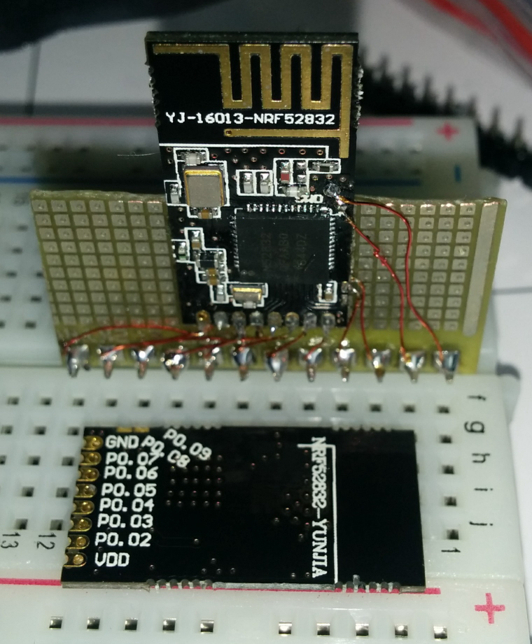
Exactly. There are two pads labelled SWD and SWC, originally meant for pogo pins.
I patched them with wires to the pin header.
Programming with a Chinese STLink V2 clone works flawlessly.
I just received 2 of those little boards.
Ideal for small sensor nodes, I'd say, but not very breadboard friendly.
So I dug out the verowire, and did a little soldering.
