[Solved]ProMini Will Not Sleep/ Enter Low Power Mode - what is best avr sleep or smartsleep?
-
I have created a very simple 4 button battery powered scene controller using a promini, an nrf24, 4 button membrane keypad and 2xAAA.
On intial run the device regeisters itself then after a short period it goes to sleep and stays asleep until a button ispressed. I use interupts on PCINT1 (4 pins) to wake up the device and transmit the subsequent scene ID which works really well - however- after 3 weeks of use the batterys died and then I realised that the promini wasnt actaully going to sleep which means not powering down.
When transmitting the device consumes 18mA, in 'so called' sleep mode it consumes 14mA.
I suspect that I am not putting the promini to sleep correctly within the MySensors framework - I have put an extract of my sketch below - can someone check the sleep mode calls and let me know if im doing something wrong?
Thx
Sleep Routine:
void loop()
  {
    if((millis() - StartTime) >= SleepWaitTime)   // Wait for some time before going to sleep
      {
        Serial.println("Sleeping....");
        delay(10);
        cli();                                    //disable interrupts
        sleep_enable ();                          // enables the sleep bit in the mcucr register

        set_sleep_mode (SLEEP_MODE_PWR_DOWN);     // set sleep mode
        ADCSRA = 0;                               //disable the ADC
        sleep_bod_disable();                      //save power
        sei();                                    //enable interrupts
        sleep_mode ();                            // goto sleep

        sleep_disable ();                         // first thing after waking from sleep:
        StartTime = millis();
        Serial.println("Awake...");
        int battery_read;                          // call function - Send the battery status
        battery_read = SendBattery();

      }
Main sketch:
#define MY_DEBUG true // Enable debug prints #define MY_RADIO_NRF24 // Enable and select radio type attached #define MY_NODE_ID 7 // >>>>>>>>Set the node ID manually - this must be set the mysensors.h call<<<<<<<<<<<<<<<<<<<<<<<<<<<<<<<< #include <MySensors.h> #include <OneButton.h> // https://github.com/mathertel/OneButton #include <avr/sleep.h> #define MIN_V 1.9 // Minimum Battery Voltage #define MAX_V 3.1 // Max Battery Voltage #define CHILD_ID_BUTTON1 1 #define CHILD_ID_BUTTON2 2 #define CHILD_ID_BUTTON3 3 #define CHILD_ID_BUTTON4 4 #define CHILD_ID_BATTERY 5 #define CHILD_ID_ADC 6 #define SN "Scene Controller" #define SV "0.4" OneButton button4(A1, true); // Setup a new OneButton on pin A1. OneButton button1(A2, true); // Setup a new OneButton on pin A2. OneButton button3(A0, true); // Setup a new OneButton on pin A0. OneButton button2(A3, true); // Setup a new OneButton on pin A3. int SendDelay = 500; // Time to wait before sending data over the radio int BATTERY_SENSE_PIN = A5; // Define battery sense pins int oldBatteryPcnt = 0; //int batteryCounter = BATTERY_REPORT_CYCLE -1; // counter for battery update //int reportCounter = FORCE_TRANSMIT_CYCLE -1; // counter for the loop and forcing updates unsigned long StartTime = 10000; unsigned long SleepWaitTime = 10000; // 10 seconds int MessageA = 0; // Button Message Values 0- no value int MessageB = 1; // up int MessageC = 2; // down int MessageD = 3; // toggle on/off MyMessage msgButton1(CHILD_ID_BUTTON1, V_SCENE_ON); MyMessage msgButton2(CHILD_ID_BUTTON2, V_SCENE_ON); MyMessage msgButton3(CHILD_ID_BUTTON3, V_SCENE_ON); MyMessage msgButton4(CHILD_ID_BUTTON4, V_SCENE_ON); MyMessage msgBattery(CHILD_ID_BATTERY, V_VOLTAGE); MyMessage msgADCValue(CHILD_ID_ADC, V_VOLTAGE); /* #################################################### # # # Presentaion # # # #################################################### */ void presentation() { sendSketchInfo(SN, SV); wait(SendDelay); // Send the sketch version information to the gateway present(CHILD_ID_BUTTON1, S_SCENE_CONTROLLER); wait(SendDelay); // Register all sensors to gw (they will be created as child devices) present(CHILD_ID_BUTTON2, S_SCENE_CONTROLLER); wait(SendDelay); present(CHILD_ID_BUTTON3, S_SCENE_CONTROLLER); wait(SendDelay); present(CHILD_ID_BUTTON4, S_SCENE_CONTROLLER); wait(SendDelay); present(CHILD_ID_BATTERY, S_MULTIMETER); wait(SendDelay); present(CHILD_ID_ADC, S_MULTIMETER); wait(SendDelay); // metric = getControllerConfig().isMetric; } /* #################################################### # # # Interupt Service Routine # # # #################################################### */ ISR (PCINT1_vect) // handle pin change interrupt for A0 to A5 here { //Serial.println("--**-INTERRUPT-**--"); //debug } /* #################################################### # # # Void Setup # # # #################################################### */ void setup() { analogReference(INTERNAL); Serial.begin(115200); // Setup the Serial port. see http://arduino.cc/en/Serial/IfSerial Serial.println("Starting..."); delay(10); // Setup Interrupts PCMSK1 |= bit (PCINT8); // enable pin A0 PCMSK1 |= bit (PCINT9); // enable pin A1 PCMSK1 |= bit (PCINT10); // enable pin A2 PCMSK1 |= bit (PCINT11); // enable pin A3 PCIFR |= bit (PCIF1); // clear any outstanding interrupts PCICR |= bit (PCIE1); // enable pin change interrupts for A0 to A5 button1.attachClick(click1); // Button 1 functions. button1.attachDoubleClick(doubleclick1); button1.attachLongPressStop(longPressStop1); button2.attachClick(click2); // Button 2 functions. button2.attachDoubleClick(doubleclick2); button2.attachLongPressStop(longPressStop2); button3.attachClick(click3); // Button 3 functions. button3.attachDoubleClick(doubleclick3); button3.attachLongPressStop(longPressStop3); button4.attachClick(click4); // Button 4 functions. button4.attachDoubleClick(doubleclick4); button4.attachLongPressStop(longPressStop4); } /* #################################################### # # # Void Loop # # # #################################################### */ void loop() { if((millis() - StartTime) >= SleepWaitTime) // Wait for some time before going to sleep { Serial.println("Sleeping...."); delay(10); cli(); //disable interrupts sleep_enable (); // enables the sleep bit in the mcucr register set_sleep_mode (SLEEP_MODE_PWR_DOWN); // set sleep mode ADCSRA = 0; //disable the ADC sleep_bod_disable(); //save power sei(); //enable interrupts sleep_mode (); // goto sleep sleep_disable (); // first thing after waking from sleep: StartTime = millis(); Serial.println("Awake..."); int battery_read; // call function - Send the battery status battery_read = SendBattery(); } button1.tick(); // Watch the push buttons: button2.tick(); button3.tick(); button4.tick(); delay(10); } -
Thank you for the reply
I am using 4 pins/ switches that I need to monitor
Is it possible to use PCINT1 for the interupt definition (pin change) when using the mysensors sleep() method or does it have to be definined as pin 2 and 3 only?
update: answering my own question no its not possible - while a sketch compiles using the PCINT1 it does not wake up the device
-
Check this for an example
https://github.com/rikki78/MySensors/blob/master/WallRemote/WallRemote.ino
@electrik I assume the example if for an earlier version of MySensors 1.x - is this method still valid for 2.x onwards?
-
Hmm is it that old already 🤔
The sketch uses a different library for the sleep functions, if I remember correctly. So if you use this sketch you should port the mysensors part to 2.x, otherwise just use the sleep functions in your own sketch.
Hope it helps -
Thank you for the reply
I am using 4 pins/ switches that I need to monitor
Is it possible to use PCINT1 for the interupt definition (pin change) when using the mysensors sleep() method or does it have to be definined as pin 2 and 3 only?
update: answering my own question no its not possible - while a sketch compiles using the PCINT1 it does not wake up the device
@gardensheddev Perhaps you might clarify how your pro-mini has been modified and that it has been modified for low voltage operation?
Even a 3.3v pro-mini with power LED and regulator removed should be <5mA active ( minus effects of active radio of course) and <5 nA asleep.
I second @Yveaux's observation MySensors Sleep is way easier to implement.
For multiple inputs on either pin 2 or 3, I'm certain somebody did this here already using a resistor matrix, an analogue pin and an Interrupt pin.
The principle was the promini is wakened from Sleep on pin 2 or 3, and the voltage read on the analogue pin determines which button was pressed.
Perhaps worth considering? ;) -
ok, so I figured it out... and just recording my observatios and fix in the hope it helps others or me if I forget :)
@yveaux and @zboblamont said to use the MyS sleep() function which can handle interupts on pins 2 & 3. For me this is too limitiing as I am using 4 pins.
What I needed was something simple for a rapid build. When I intially built the node a month ago I read up on the MyS sleep function, realised that it couldnt handle more than 2 pins for interupts and opted to go down the route of interupts as laid out on www.gammon.com.au. After a little more reading I then implemented the AVR sleep function, so far so good or so I thought - move fwd to my problem. While everything was working well:
- scene controller HW built - check,
- Software created - check,
- Enclosure printed - check,
- hooked up to home assitant - check,
- WAF (very important) - check,
...the node wasnt actaully sleeping DOH!
Upto this point I had spent less than 6 hours in dev and implementation time....
So heres the problem, after a lot of reading over the last 36 hours I found a post that states MyS library only implements interupts for pins 2&3 on the pro mini - it doesnt implement interupt groups such as PCINT1 (A0-A5) etc AND the node cannot be woken up via interupt if it is not done via pins 2&3.
@electrik posted a link to his excellent sketch that hacks the core code a little - as I was looking into this method I stumbled on a post by @freynder that implements a 'dirty hack' here which forces the node to wake up on interupt when using the MyS sleep() function. This then led me to a post on a 6/8 button controller here. These two posts have be pivotal in fixing my problem. Thank you @electrik for triggering the thought process that lead to a simple solution :)
@yveaux and @zboblamont you where both correct I need to use the MyS sleep() function which I have now implemented alongside the external interupt library form the 6/8 button controller link and the added the two lines of code as per the 'dirty hack'
My node now reads 18mA when active (transmitting) and when sleeping it is less than 0.5mA - which is the limitation of my equipment!
@zboblamont to answer your Q about node setup, I have a pro mini and with both the power led and regulator removed as per the MySensors hack for battery nodes - however the transmit led is still connected which will draw extra current when transmitting, which I am ok with for the moment lol
thank you to all that have contributed !!
heres the schematic of the controller:
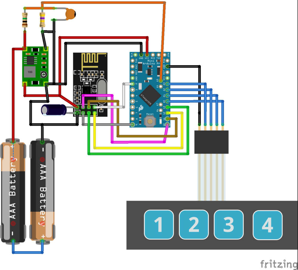
and an updated extract of the code#define MY_DEBUG true // Enable debug prints #define MY_RADIO_NRF24 // Enable and select radio type attached #define MY_NODE_ID 7 // >>>>>>>>Set the node ID manually - this must be set the mysensors.h call<<<<<<<<<<<<<<<<<<<<<<<<<<<<<<<< #include <MySensors.h> #include <OneButton.h> // https://github.com/mathertel/OneButton #define EI_NOTEXTERNAL // External interrupts managed by built-in routines #include <EnableInterrupt.h> // Pin-change interrupts #define MIN_V 1.9 // Minimum Battery Voltage #define MAX_V 3.1 // Max Battery Voltage #define CHILD_ID_BUTTON1 1 #define CHILD_ID_BUTTON2 2 #define CHILD_ID_BUTTON3 3 #define CHILD_ID_BUTTON4 4 #define CHILD_ID_BATTERY 5 #define CHILD_ID_ADC 6 #define SN "Scene Controller" #define SV "0.4" #define BUTTON4 A1 // Interput pin and button definitions #define BUTTON1 A2 #define BUTTON3 A0 #define BUTTON2 A3 OneButton button4(BUTTON4, true); // Setup a new OneButton on pin A1. OneButton button1(BUTTON1, true); // Setup a new OneButton on pin A2. OneButton button3(BUTTON3, true); // Setup a new OneButton on pin A0. OneButton button2(BUTTON2, true); // Setup a new OneButton on pin A3. int SendDelay = 500; // Time to wait before sending data over the radio int BATTERY_SENSE_PIN = A5; // Define battery sense pins int oldBatteryPcnt = 0; //int batteryCounter = BATTERY_REPORT_CYCLE -1; // counter for battery update //int reportCounter = FORCE_TRANSMIT_CYCLE -1; // counter for the loop and forcing updates unsigned long StartTime = 0; // sleep startime variable unsigned long SleepWaitTime = 10000; // Time to wait before going to sleep 10 seconds unsigned long Sleep_Time = 86400000; // 86400000 Sleep for 24 hours int MessageA = 0; // Button Message Values 0- no value int MessageB = 1; // up int MessageC = 2; // down int MessageD = 3; // toggle on/off MyMessage msgButton1(CHILD_ID_BUTTON1, V_SCENE_ON); MyMessage msgButton2(CHILD_ID_BUTTON2, V_SCENE_ON); MyMessage msgButton3(CHILD_ID_BUTTON3, V_SCENE_ON); MyMessage msgButton4(CHILD_ID_BUTTON4, V_SCENE_ON); MyMessage msgBattery(CHILD_ID_BATTERY, V_VOLTAGE); MyMessage msgADCValue(CHILD_ID_ADC, V_VOLTAGE); /* #################################################### # # # Presentaion # # # #################################################### */ void presentation() { sendSketchInfo(SN, SV); wait(SendDelay); // Send the sketch version information to the gateway present(CHILD_ID_BUTTON1, S_SCENE_CONTROLLER); wait(SendDelay); // Register all sensors to gw (they will be created as child devices) present(CHILD_ID_BUTTON2, S_SCENE_CONTROLLER); wait(SendDelay); present(CHILD_ID_BUTTON3, S_SCENE_CONTROLLER); wait(SendDelay); present(CHILD_ID_BUTTON4, S_SCENE_CONTROLLER); wait(SendDelay); present(CHILD_ID_BATTERY, S_MULTIMETER); wait(SendDelay); present(CHILD_ID_ADC, S_MULTIMETER); wait(SendDelay); // metric = getControllerConfig().isMetric; } /* #################################################### # # # Void Setup # # # #################################################### */ void setup() { analogReference(INTERNAL); Serial.begin(115200); // Setup the Serial port. see http://arduino.cc/en/Serial/IfSerial Serial.println("Starting..."); delay(10); button1.attachClick(click1); // Button 1 functions. button1.attachDoubleClick(doubleclick1); button1.attachLongPressStop(longPressStop1); button2.attachClick(click2); // Button 2 functions. button2.attachDoubleClick(doubleclick2); button2.attachLongPressStop(longPressStop2); button3.attachClick(click3); // Button 3 functions. button3.attachDoubleClick(doubleclick3); button3.attachLongPressStop(longPressStop3); button4.attachClick(click4); // Button 4 functions. button4.attachDoubleClick(doubleclick4); button4.attachLongPressStop(longPressStop4); enableInterrupt(BUTTON1,Int_vect,CHANGE); enableInterrupt(BUTTON2,Int_vect,CHANGE); enableInterrupt(BUTTON3,Int_vect,CHANGE); enableInterrupt(BUTTON4,Int_vect,CHANGE); } /* #################################################### # # # Void Loop # # # #################################################### */ void loop() { if((millis() - StartTime) >= SleepWaitTime) // Wait for some time before going to sleep { Serial.println("Sleeping...."); delay(10); sleep(Sleep_Time); // Sleepy Time :) // WAKE UP HERE _wokeUpByInterrupt = INVALID_INTERRUPT_NUM; //dirty hack wake up routine - clear interupt StartTime = millis(); Serial.println("Awake..."); int battery_read; // call function - Send the battery status battery_read = SendBattery(); } button1.tick(); // Check the push buttons: button2.tick(); button3.tick(); button4.tick(); delay(10); } /* #################################################### # # # Interupt Service Routine # # # #################################################### */ void Int_vect() // handle pin change interrupt for A0 to A5 here { //Serial.println("--**-INTERRUPT-**--"); //debug _wokeUpByInterrupt = 0xFE; // Dirty hack to get out of MySensors sleep loop }
Hello! It looks like you're interested in this conversation, but you don't have an account yet.
Getting fed up of having to scroll through the same posts each visit? When you register for an account, you'll always come back to exactly where you were before, and choose to be notified of new replies (either via email, or push notification). You'll also be able to save bookmarks and upvote posts to show your appreciation to other community members.
With your input, this post could be even better 💗
Register Login