Simplest PCB - Atmega328p - NRF24L01+ - SI7021
-
Hello,
I would like to have the simplest PCB possible to just transmit humidity and temperature (objective : round PCB radius 25 mm in a wooden "box").
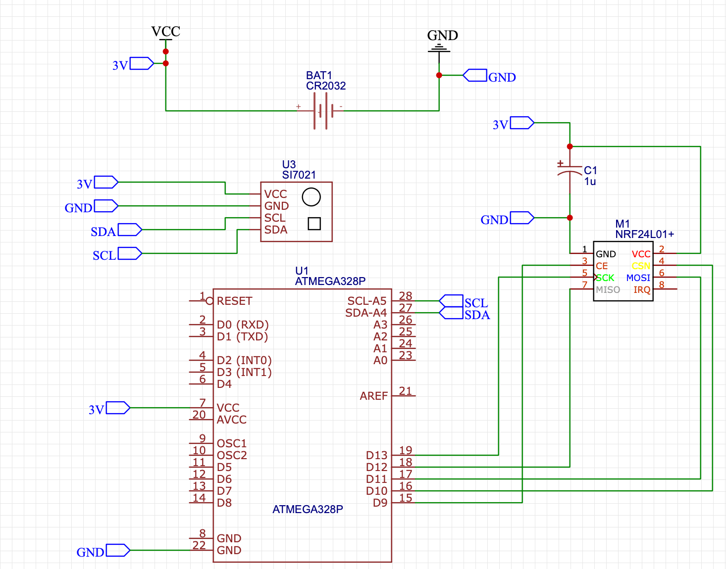
For now, I have added only these components in the schematic:

I believe it can work this way. But will it be stable in your opinion ?
Thanks ! -
Hi @ryolaxe
I highly suggest using a larger capacitor of at least 100µF if you intend to run off a CR2032 coin cell. This will stabilize the voltage when the radio is active, may allow you to operate it at a higher PA level and increase the usable capacity of the battery. I have some more detailed information in this and this post.
You also shouldn't leave the RESET pin floating, or else the MCU might reset anytime. Pull it high using a 10k ohm resistor.
Add 100nF ceramic capacitors ideally to every VCC/GND pair. It is also recommended to connect AREF with a 100nF capacitor to ground, even if you do not intend to use the ADC.
If your SI7021 module doesn't have pullup resistors for SDA and SCL onboard, you should add them aswell.
-
Hi @BearWithBeard,
Thanks for your answer.
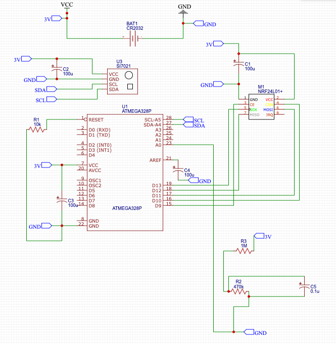
I've added / modified the capacitors and also added a measurement for the battery voltage.
I'm converting it to PCB in EasyEDA now, but It doesn't want to rotate the elements (NRF24 for example). Have you had similar problems ?
Edit : Screenshot
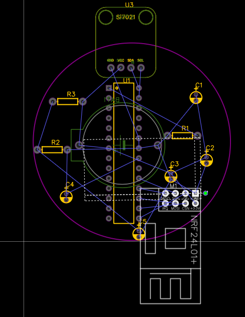
The NRF24 is rotated (hyphen lines) but none of the pins or even the module really rotates...
-
Sorry, I can't help you with EasyEDA. I'm familiar with EAGLE and KiCAD only.
Maybe I've been too ambiguous or you misunderstood what I wrote earlier. I suggested to add 100 nF (Nanofarad; 100 nF = 0.1 µF) ceramic capacitors to every VCC/GND pair, but you have added 100 µF (Microfarad) electrolytic capacitors in your schematic. With "every VCC/GND pair" I was referring to the ATmega only, which has multiple VCC/GND pins (pins 7+8 and 20+22 for the THT package you are using), not to every device / module in your circuit. Change C1, C3 and C3 to 100 nF ceramic and add 100 µF electrolytic as a buffer. You can remove C2.
You are now pulling RESET low, which means you are holding the MCU in a reset state forever. Pull it high to VCC instead.
If you are going to use a voltage divider to measure the battery voltage, you have to read the voltage in between the two resistors. Refer to the Measuring and Reporting Battery Level section in the Battery Powered Sensors guide for the proper setup. You could also measure the voltage without external hardware if you want to keep it minimal. Here's an example sketch.
Besides that, I highly suggest you build your circuit on a breadboard or similar first and test it before you order your designed PCB.
Hello! It looks like you're interested in this conversation, but you don't have an account yet.
Getting fed up of having to scroll through the same posts each visit? When you register for an account, you'll always come back to exactly where you were before, and choose to be notified of new replies (either via email, or push notification). You'll also be able to save bookmarks and upvote posts to show your appreciation to other community members.
With your input, this post could be even better 💗
Register Login