110v-230v AC to Mysensors PCB board
-
Hi All,
I'm not sure if I understand the 2-wire thing completely, but in my house (which is kind of standard I guess in Europe) I have 3 wires going from the electricity cabinet, to the light switch and then to the light bulb. These cables are Phase, Neutral and Ground.
As I don't want to rewire my entire grid, I decided to build these boards so I can reuse the current wiring. I ended up with the following "schematic" if I can call my paintskills like that.
The enclosure at the bottom of the drawing would be placed behind the current light switch, while the enclosure at the top of the drawing would be placed right above the light bulb. This requires little to no modification of my current wiring.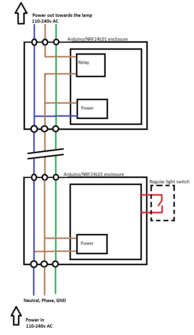
@ServiceXP, I'll update the title to include the 110v information.
-
Why don't you place the relay behind the switch, too? This way you could save half of the nodes.
I have just ordered some of those power supply modules. Very interesting, cheapest similar ones I found before were about 14 €.
-
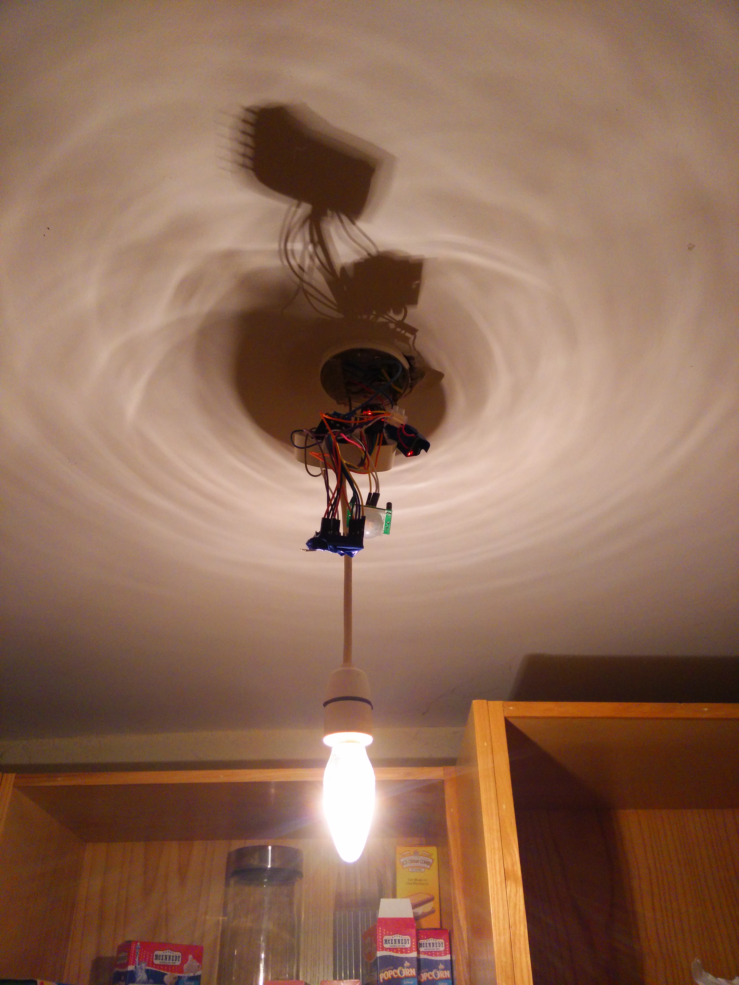
This is what I have done for a light bulb in the pantry with a motion sensor. Its a mess as it is a proof of concept.
I have a 5 separate "modules" as such. Arduino Pro Mini, Motion Sensor, Radio, 5V AC/DC transformer and a 5V Relay. So clearly it is too big and a bit of a mess! So I am really interested in your PCB @aproxx! Do let us know how it works for you.
-
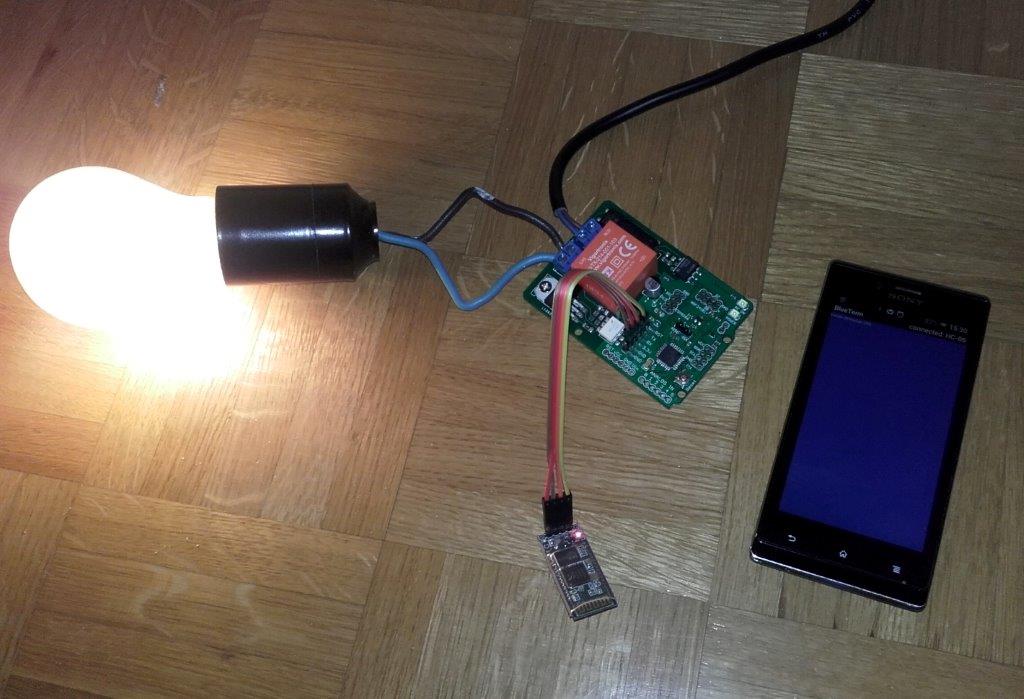
There is something similar I'm working on. Although mine is more like a solid state relay. And it can be used as an AC dimmer. But has the same concept with AC-DC converter. I used one from Vigortronix. It has a 3.3V output.
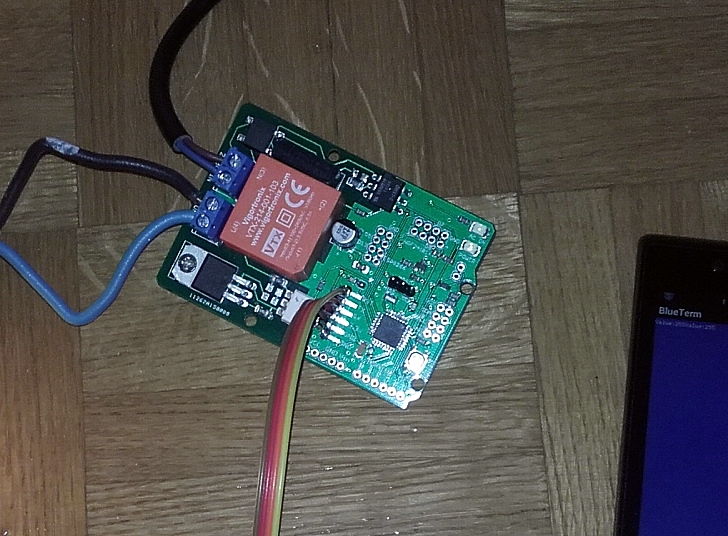
Here it is controlled with Bluetooth serial connection
This is how the board looks like
If anyone wants it, let me know.@aproxx I like your form factor. Great find with that AC-DC converter.
-
Those are even much smaller (3.3v , 25x38x17 mm , 3w) and have similar price. I've got one (still to experiment with)
-
Too bad these Ac Dc are so expensive and little big. But good quality for sure.
@ceech : looks like a pretty board. I am interested in your files please. It could be useful..:wink:
@scalz Here you go:
https://github.com/ceech/AC-dimmer
Enjoy. -
thank you!
-
This is really interesting.
If this PCB succeeds i will order maybe 10-15 of them. They need to be so small it can be mounted inside/behind the wallswitch and i also want to combine it with some sort of motion detector fittet in the wallswitch as well...
Cool really looking forward to this... keep up the good work!
-
@Jan-Gatzke You are absolutely right. No idea on why I've never thought about that!
I have now redesigned the board to fit a relay as well. Size is still limited to 45 by 45mm, so it should be quite easy to place them behind a light switch.I hope to receive my PCB boards next week, after which I'll add all components to the board and start testing it. If all goes well, I'll be submitting the new design with relay to dirtyPCBs to have those printed too.
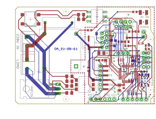
Just a sneak peak of the new board:
Top:
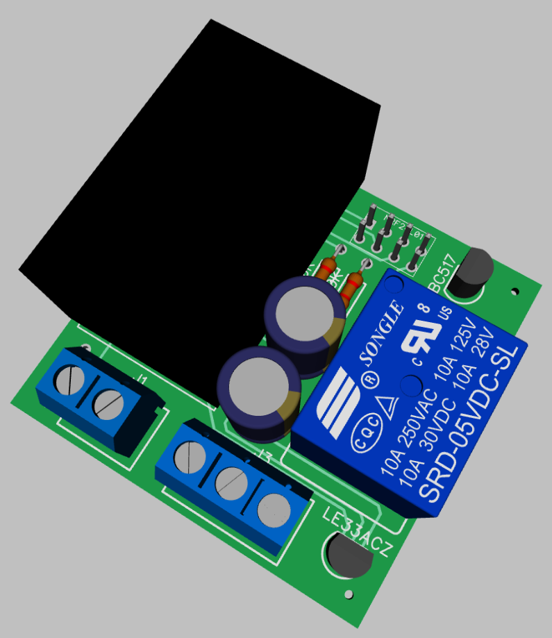
Bottom:
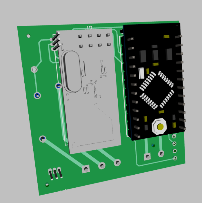
In the following days I'll start designing a 3d-printable casing to fit the board.
As soon as I have confirmed that the board with relay is working fine, I'll submit the PCB design here together with the 3d printable casing. Due to slow shipping and limited spare time I expect this to happen in about 4 to 7 weeks. -
YES - this is really what im looking for!! :)
Well done @aproxx - i will follow this closely.If you have the space - the pcb could have a input/hole for an external sensor to pin 3 (if unused or another one). so you can add say external motion sensor or temp as well.
Can you list the parts so there is a possibility to start ordering those?
-
@sundberg84 Thanks for the kind words!
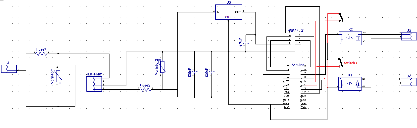
The new design (with relay) indeed has a few digital pins available. I've included the following in this design:- 4 digital in and output pins. Pin 3, 4, 5 and 6. Pin 3 is also used to switch the relay, so 3 other digital pins are available to connect other things like motion sensors and switches.
- 1 Analog input pin. Pin A0.
- 2 5v pins.
- 2 Ground pins.
- A few extra empty pins which aren't connected to anything, but can be used to add some custom things if needed.
Bill of materials is available below, together with Gerber files, and DIP file (as I'm using Diptrace to design my PCBs).
Please keep in mind that this is only my second time designing PCBs, so if you'd like to be 100% sure it works I would recommend to wait until I've tested the board and confirmed that everything is working fine.
But feedback is always welcome!
Mysensors v2.1 UNTESTED.rar -
@sundberg84 Thanks for the kind words!
The new design (with relay) indeed has a few digital pins available. I've included the following in this design:- 4 digital in and output pins. Pin 3, 4, 5 and 6. Pin 3 is also used to switch the relay, so 3 other digital pins are available to connect other things like motion sensors and switches.
- 1 Analog input pin. Pin A0.
- 2 5v pins.
- 2 Ground pins.
- A few extra empty pins which aren't connected to anything, but can be used to add some custom things if needed.
Bill of materials is available below, together with Gerber files, and DIP file (as I'm using Diptrace to design my PCBs).
Please keep in mind that this is only my second time designing PCBs, so if you'd like to be 100% sure it works I would recommend to wait until I've tested the board and confirmed that everything is working fine.
But feedback is always welcome!
Mysensors v2.1 UNTESTED.rar@aproxx Looks great so far. I am missing a diode and snubber components around the relay. Or are those just not visible? Didn't have a look at the files, yet. In another thread someone posted a diy solid state relay with triacs. This would be a little bit smaller than the relay and would less likely fail. I would add a fuse in front of the power supply, too.
I will definitly have a look at Diptrace. I like those 3D previews. :)
-
@Jan Gatzke There is a diode in place, but it just isn't visible in that current 3D design. I've used following schematic (minus the LED) to connect the relay to pin 3 of the Arduino :
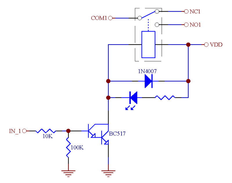
What do you mean by "less likely to fail" about these relays? I've been using them for a while now, but never had any issues with these. Or do you think that they might show this problem when using them for a long time?
-
Yes, relays are mechanical parts. Cheap ones are likely to fail over time. The missing snubber protection in your circuit will kill them, too when connecting inductive loads.
-
Hi all,
After all input you guys gave me, combined with the findings of this topic, I decided to go back to the drawing board.
Before submitting my newly designed PCB I would like to make sure it doesn't contain any (obvious) mistakes.
Two questions I still have are:- I assume it is correct that all ground pins are connected to each other? So both for the 5v parts of the circuit and the 3.3v circuit?
- The HLK-PM01 seems to provide a quite stable voltage somewhere between 4.9 and 5.1 volts. If I understand correctly I should directly connect this to VCC input of the Arduino Pro Mini, and NOT to the RAW input voltage?
Any other remarks on the current design are welcome as well of course! :)
Schematic
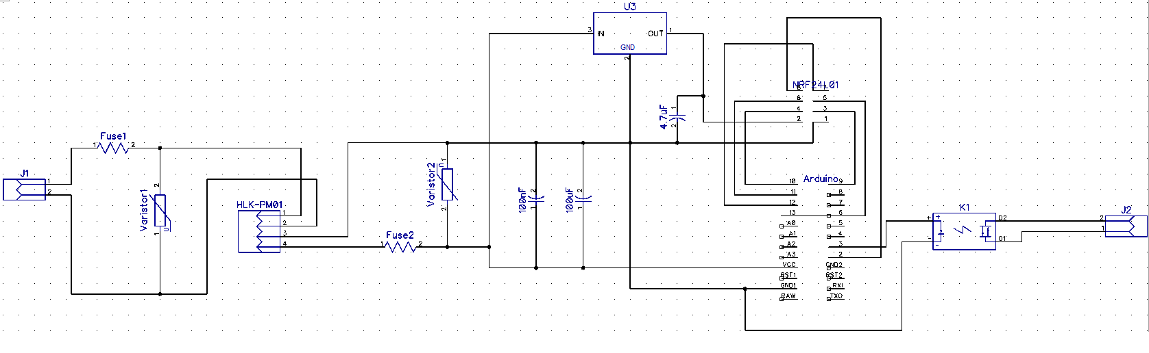
Components (from left to right)
J1 2 Pin screw terminal (Power input)
Fuse1 PTC Resettable Fuses 250V 1A TRF250-1000 PPTC Polymeric PTC PolySwitch
Varistor1 Varistor 10D391K 10D-391K VDR 10K391 Metal voltage dependent resistor
HLK-PM01 HLK-PM01 230v AC – 5v DC converter
Fuse2 PTC Resettable Fuses 250V 1A TRF250-1000 PPTC Polymeric PTC PolySwitch
Varistor2 SMD 1206 5.5V Varistor original Varistor resistor 100pcs/lot
C1 100nF capacitor
C2 100uF capacitor
U3 LE33ACZ 5v to 3.3v converter
C3 4.7uF capacitor
NRF24L01 Normal NRF24L01(+) module
Arduino Arduino Pro Mini 5v
K1 G3MB-202P 240V AC 2A Solid State relay
J2 2 Pin screw terminal -
Hi all,
After all input you guys gave me, combined with the findings of this topic, I decided to go back to the drawing board.
Before submitting my newly designed PCB I would like to make sure it doesn't contain any (obvious) mistakes.
Two questions I still have are:- I assume it is correct that all ground pins are connected to each other? So both for the 5v parts of the circuit and the 3.3v circuit?
- The HLK-PM01 seems to provide a quite stable voltage somewhere between 4.9 and 5.1 volts. If I understand correctly I should directly connect this to VCC input of the Arduino Pro Mini, and NOT to the RAW input voltage?
Any other remarks on the current design are welcome as well of course! :)
Schematic
Components (from left to right)
J1 2 Pin screw terminal (Power input)
Fuse1 PTC Resettable Fuses 250V 1A TRF250-1000 PPTC Polymeric PTC PolySwitch
Varistor1 Varistor 10D391K 10D-391K VDR 10K391 Metal voltage dependent resistor
HLK-PM01 HLK-PM01 230v AC – 5v DC converter
Fuse2 PTC Resettable Fuses 250V 1A TRF250-1000 PPTC Polymeric PTC PolySwitch
Varistor2 SMD 1206 5.5V Varistor original Varistor resistor 100pcs/lot
C1 100nF capacitor
C2 100uF capacitor
U3 LE33ACZ 5v to 3.3v converter
C3 4.7uF capacitor
NRF24L01 Normal NRF24L01(+) module
Arduino Arduino Pro Mini 5v
K1 G3MB-202P 240V AC 2A Solid State relay
J2 2 Pin screw terminal
Hello! It looks like you're interested in this conversation, but you don't have an account yet.
Getting fed up of having to scroll through the same posts each visit? When you register for an account, you'll always come back to exactly where you were before, and choose to be notified of new replies (either via email, or push notification). You'll also be able to save bookmarks and upvote posts to show your appreciation to other community members.
With your input, this post could be even better 💗
Register Login