Magnetic field detection
-
Hello everyone...
i try to build a Anemometer with an AS5040-Chip.... so it would be great to use mysensors with an Anemometer...
does anyone have a similar project? maybe there are wiring-plans for the as5040 and arduinos?thanks for help..
-
Hello everyone...
i try to build a Anemometer with an AS5040-Chip.... so it would be great to use mysensors with an Anemometer...
does anyone have a similar project? maybe there are wiring-plans for the as5040 and arduinos?thanks for help..
@michlb1982 This site shows how to connect an AS5040 to an Arduino and has a sample sketch: http://reprap.org/wiki/Magnetic_Rotary_Encoder_1.0. The section is towards the bottom called Digital SSI Output. None of the pins used conflict with NRF24 radio usage so it should be relatively simple to MySensor it.
Cheers
Al -
Hello
thanks for the input...
well i did it...
i was able to build an Wind-direction-MYSENSOR... well i'm sure, its a little bit
awkward and much to complicated but it works quite OK...
the next step is to build a windspeed - sensor.. with the AS5040..here the Arduino nano Code...:
#include <SPI.h>
#include <MySensor.h>

const int ledPin = 13; //LED connected to digital pin 13
const int clockPin = 5; //output to clock
const int CSnPin = 4; //output to chip select
const int inputPin = 6; //read AS5040

int inputstream = 0; //one bit read from pin
long packeddata = 0; //two bytes concatenated from inputstream
long angle = 0; //holds processed angle value
long anglemask = 65472; //0x1111111111000000: mask to obtain first 10 digits with position info
long statusmask = 63; //0x000000000111111; mask to obtain last 6 digits containing status info
long statusbits; //holds status/error information
int DECn; //bit holding decreasing magnet field error data
int INCn; //bit holding increasing magnet field error data
int OCF; //bit holding startup-valid bit
int COF; //bit holding cordic DSP processing error data
int LIN; //bit holding magnet field displacement error data
int debug = 0; //SET THIS TO 0 TO DISABLE PRINTING OF ERROR CODES
int shortdelay = 1000; // this is the microseconds of delay in the data clock
int longdelay =1000; // this is the milliseconds between readings
#define CHILD_ID_DIR 0
//#define INTERRUPT inputPin
MySensor gw;
MyMessage msgDIR(CHILD_ID_DIR, V_DIRECTION);

void setup()
{
  gw.begin(NULL, AUTO, true, AUTO);
  Serial.begin(250000);
  pinMode(ledPin, OUTPUT); // visual signal of I/O to chip
  pinMode(clockPin, OUTPUT); // SCK
  pinMode(CSnPin, OUTPUT); // CSn -- has to toggle high and low to signal chip to start data transfer
  pinMode(inputPin, INPUT); // SDA

  // Send the Sketch Version Information to the Gateway
  gw.sendSketchInfo("Winddirection", "1.0");
  // Register all sensors to gw (they will be created as child devices)
  gw.present(CHILD_ID_DIR, S_WIND);
}

void loop()
{
// CSn needs to cycle from high to low to initiate transfer. Then clock cycles. As it goes high
// again, data will appear on sda
  digitalWrite(CSnPin, HIGH); // CSn high
  digitalWrite(clockPin, HIGH); // CLK high
  delay(longdelay);// time between readings
  digitalWrite(ledPin, HIGH); // signal start of transfer with LED
  digitalWrite(CSnPin, LOW); // CSn low: start of transfer
  delayMicroseconds(shortdelay); // delay for chip initialization
  digitalWrite(clockPin, LOW); // CLK goes low: start clocking
  delayMicroseconds(shortdelay); // hold low
  for (int x=0; x <16; x++) // clock signal, 16 transitions, output to clock pin
  {
    digitalWrite(clockPin, HIGH); //clock goes high
    delayMicroseconds(shortdelay); //
    inputstream =digitalRead(inputPin); // read one bit of data from pin
//Serial.print(inputstream, DEC);
    packeddata = ((packeddata << 1) + inputstream);// left-shift summing variable, add pin value
    digitalWrite(clockPin, LOW);
    delayMicroseconds(shortdelay); // end of one clock cycle
  }
// end of entire clock cycle
//Serial.println(" ");
  digitalWrite(ledPin, LOW); // signal end of transmission
// lots of diagnostics for verifying bitwise operations
//Serial.print("packed:");
//Serial.println(packeddata,DEC);
//Serial.print("pack bin: ");
//Serial.println(packeddata,BIN);
  angle = packeddata & anglemask; // mask rightmost 6 digits of packeddata to zero, into angle.
//Serial.print("mask: ");
//Serial.println(anglemask, BIN);
//Serial.print("bin angle:");
//Serial.println(angle, BIN);
//Serial.print("angle: ");
//Serial.println(angle, DEC);
  angle = (angle >> 6); // shift 16-digit angle right 6 digits to form 10-digit value
//Serial.print("angleshft:");
//Serial.println(angle, BIN);
//Serial.print("angledec: ");
//Serial.println(angle, DEC);
  angle = angle * 0.3515; // angle * (360/1024) == actual degrees
  Serial.print("angle: "); // and, finally, print it.
  Serial.println(angle, DEC);
//Serial.println("--------------------");
//Serial.print("raw: "); // this was the prefix for the bit-by-bit diag output inside the loop.
  if (debug)
  {
    statusbits = packeddata & statusmask;
    DECn = statusbits & 2; // goes high if magnet moved away from IC
    INCn = statusbits & 4; // goes high if magnet moved towards IC
    LIN = statusbits & 8; // goes high for linearity alarm
    COF = statusbits & 16; // goes high for cordic overflow: data invalid
    OCF = statusbits & 32; // this is 1 when the chip startup is finished.
    if (DECn && INCn) { Serial.println("magnet moved out of range"); }
    else
    {
      if (DECn) { Serial.println("magnet moved away from chip"); }
      if (INCn) { Serial.println("magnet moved towards chip"); }
    }
    if (LIN) { Serial.println("linearity alarm: magnet misaligned? Data questionable."); }
    if (COF) { Serial.println("cordic overflow: magnet misaligned? Data invalid."); }
  }
  float V_DIRECTION = angle;
  gw.send(msgDIR.set(V_DIRECTION, DEC));
  packeddata = 0; // reset both variables to zero so they don't just accumulate
  angle = 0;
  gw.process();
  //gw.sleep(INTERRUPT,CHANGE);
  gw.sleep(longdelay);
}
the code for FHEM:
define MYSENSOR_111 MYSENSORS_DEVICE 111
attr MYSENSOR_111 IODev SerialGate
attr MYSENSOR_111 alias Windrichtung
attr MYSENSOR_111 group Sensoren
attr MYSENSOR_111 mapReading_direction 0 direction
attr MYSENSOR_111 mapReading_gust 0 gust
attr MYSENSOR_111 mapReading_wind 0 wind
attr MYSENSOR_111 mode repeater
attr MYSENSOR_111 room 03_Umwelt
attr MYSENSOR_111 stateFormat {sprintf("%.0f",ReadingsVal("MYSENSOR_111","direction",0))."°"}
a curcuit will follow in the next days...
greets..
Mike -
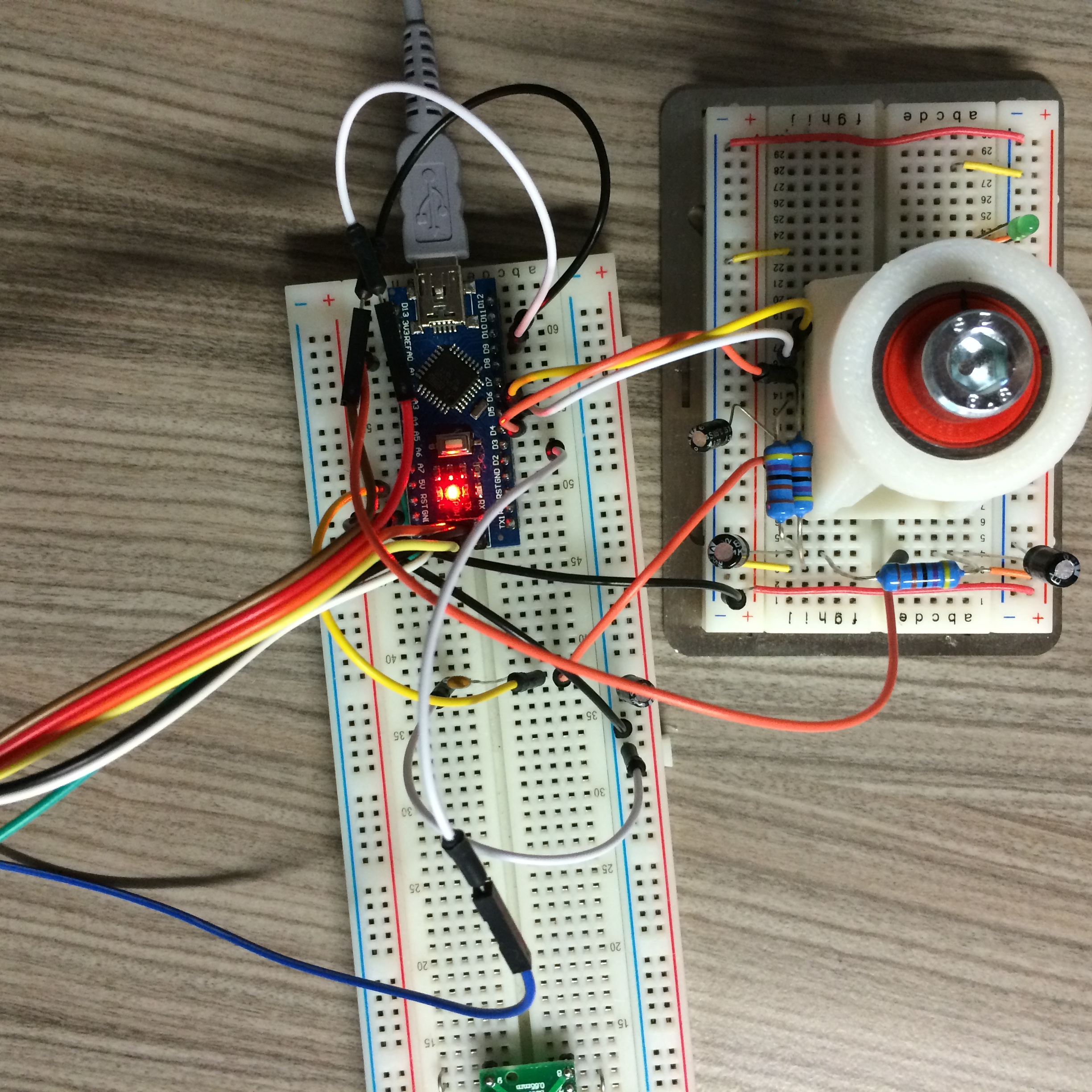
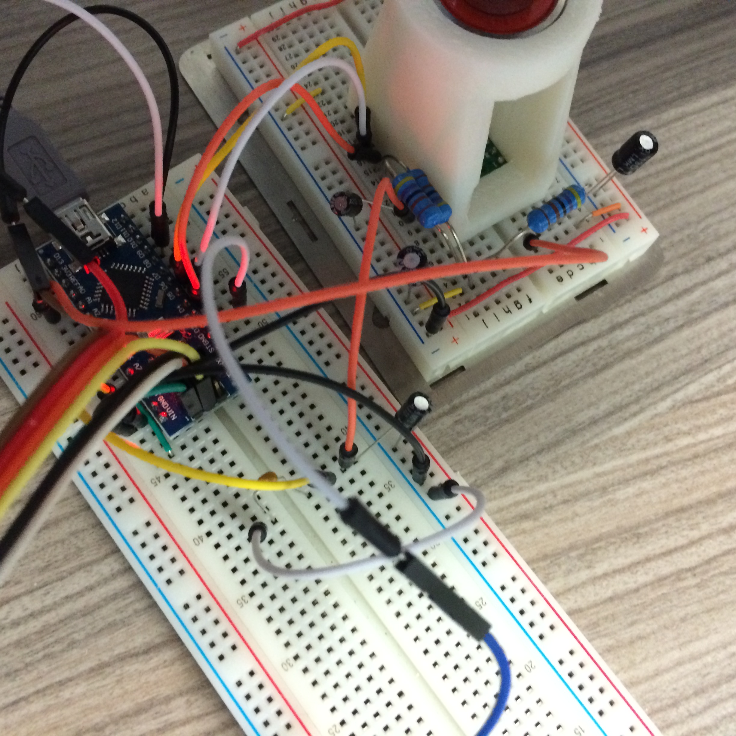
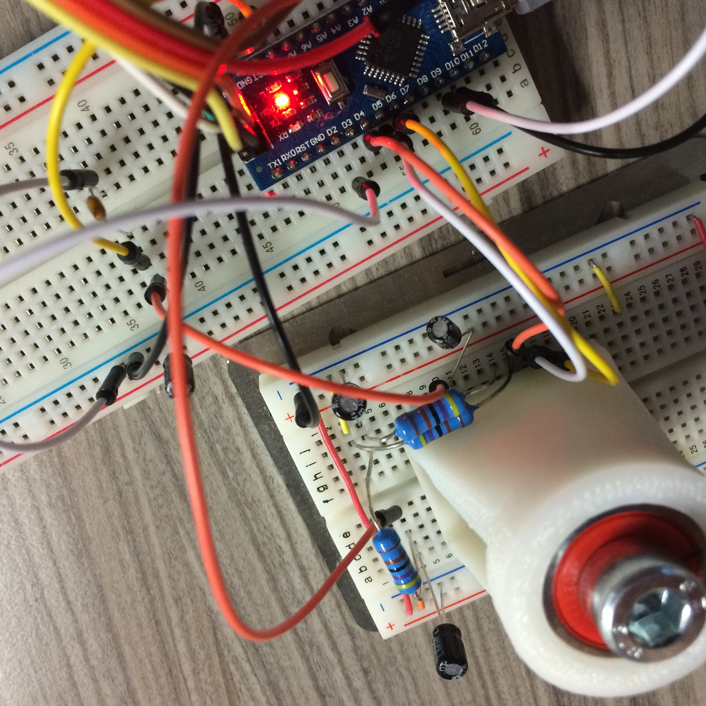
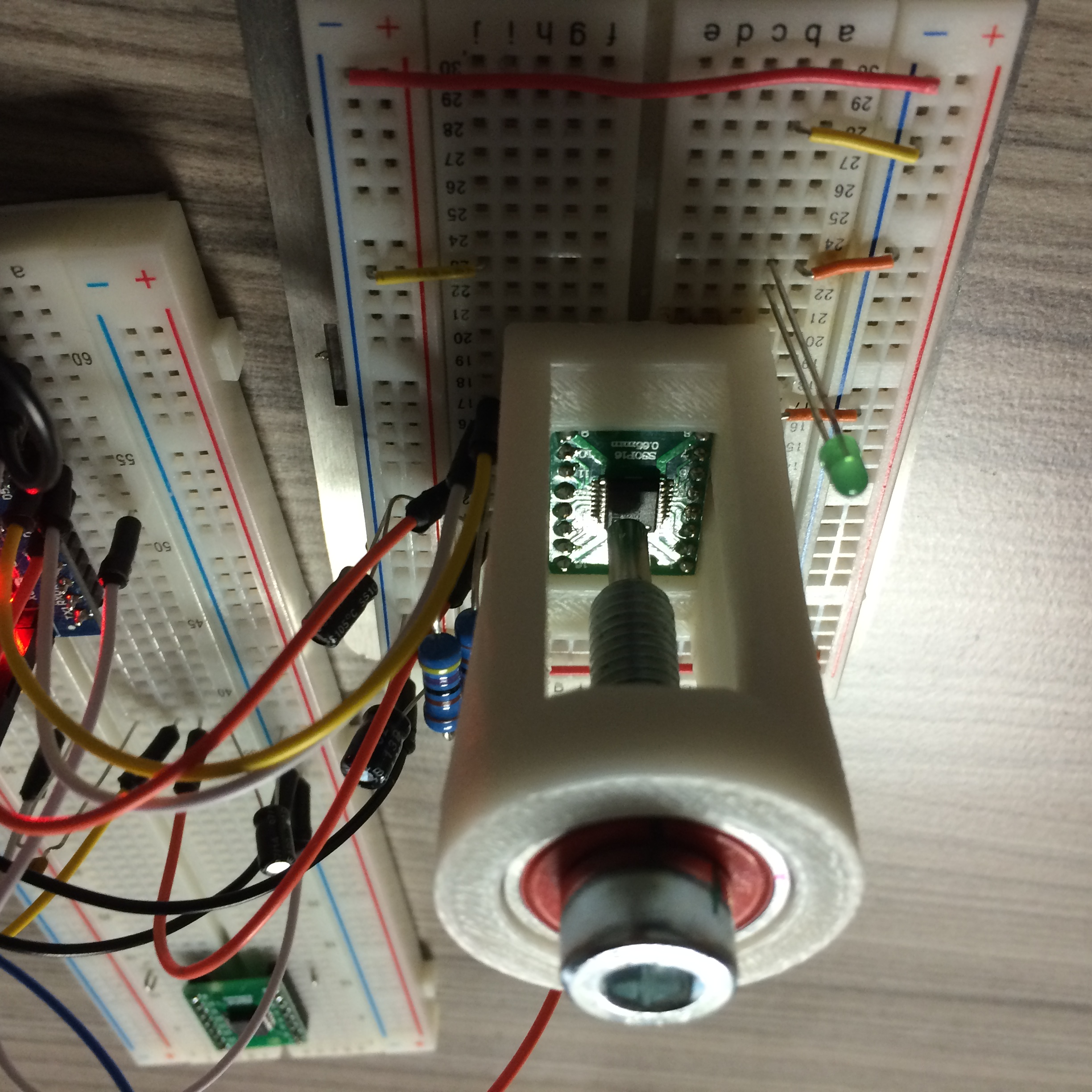
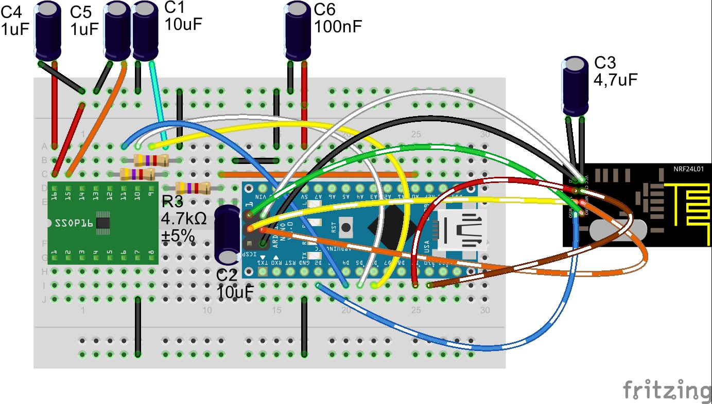
here some pics
-
well, the promised curcuit...Windrichtung-AS5040-Mysensor.pdf
 Windrichtung.fzz
Hello! It looks like you're interested in this conversation, but you don't have an account yet.
Getting fed up of having to scroll through the same posts each visit? When you register for an account, you'll always come back to exactly where you were before, and choose to be notified of new replies (either via email, or push notification). You'll also be able to save bookmarks and upvote posts to show your appreciation to other community members.
With your input, this post could be even better 💗
Register Login