
My Slim 2AA Battery Node
-
-
@Cliff-Karlsson I'm experimenting with several versions of Optiboot (various upload and upload combinations) for my board. Once that is done, I will add it to the documentation of my board. I'm extending the sketch found here:
-
anyone care to write down the exact precedure of how to burn a new bootloader to the atmel chip? what files goes to what folders and so on.
@Cliff-Karlsson Let's continue your bootloader trouble discussion in it's own thread:
http://forum.mysensors.org/topic/2975/how-do-i-burn-a-bootloader-to-an-328p-with-uno-bootloader-preinstalled/8 -
OK, so finally I have received most of the parts I need to build a few of these sensors. I want to go with a temp sensor at first, the si7021. So I wanted to check what "other bits" I need (newb alert).
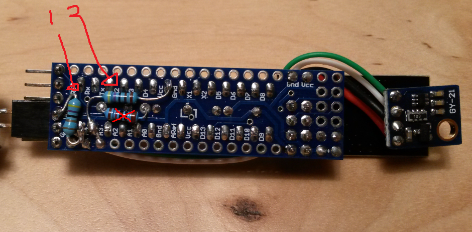
From there, do I need both 1 and 2? If so, what are these?
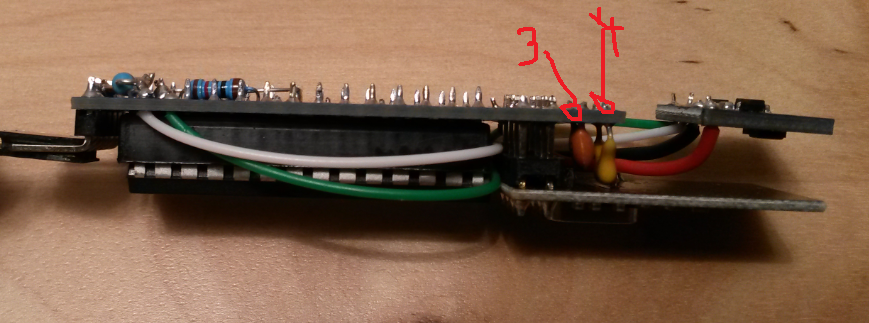
From here, what are 3 and 4? Do I need both?
Also, depending on the answers above, do I solder to exactly the same pins? Have I missed anything?
Thanks
-
Ok, finaly succeded in burning the bootloader. Now comes next part. Fuses and lockbits, I have no idea what this means but is this what I need to do?
avrdude -C ../etc/avrdude.conf -c usbasp -B5 -p ATmega328P -U lfuse:w:0x62:m -U hfuse:w:0xDE:m -U efuse:w:0x07:m -U lock:w:0x2F:m -
-
-
Web-based fuse calculator
A different way of evaluating fuses is presented at this web page:
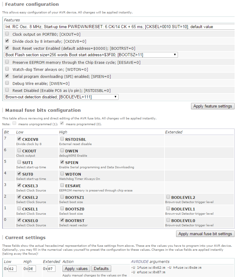
http://www.engbedded.com/fusecalcAt the bottom I inserted your fuses.
Translation:
Divide by8-> if your mcy board uses 8Mhz, then you now use 1Mhz Clock (Good this enables that you now can use a lower voltage down to 1,9V)
SPI is enabled, then you can program your mcu with FTDI cable
BOD mcu will not power down mcu when you have a low voltage (So you can use down to 1,9V)
I write 1,9Volt since this is the lowest voltage your NRF24L01+ can use for operation -
Sorry for asking the same questions over and over but I have just used the files linked at the top of this thread.
This is the bootloader that I used:
atmega328_1a.hex (Optiboot for 9600baud at 1MHz)############################################################## # Add the new board to boards.txt (normally located at "C:\Program Files\Arduino\hardware\arduino\avr" # The *.bootloader.* etries only matters if you want to program bootloader (and fuses) from Arduino IDE. # See http://www.engbedded.com/fusecalc (select Atmega328p) for interpretation of fuse values and how # extended fuses are written in different applications (07h in Arduino IDE = FFh in Atmel studio). ############################################################## apm96.name=APM Optiboot internal 1MHz noBOD 9600baud apm96.upload.tool=avrdude apm96.upload.protocol=arduino apm96.upload.maximum_size=32256 apm96.upload.speed=9600 apm96.bootloader.tool=avrdude apm96.bootloader.low_fuses=0x62 apm96.bootloader.high_fuses=0xde apm96.bootloader.extended_fuses=0x07 apm96.bootloader.path=optiboot_v50 apm96.bootloader.file=atmega328_1a.hex apm96.bootloader.unlock_bits=0x3F apm96.bootloader.lock_bits=0x2F apm96.build.mcu=atmega328p apm96.build.f_cpu=1000000L apm96.build.core=arduino apm96.build.variant=standardDo I still need to add fuses or is that done when the bootloader is burned?
-
Sorry for asking the same questions over and over but I have just used the files linked at the top of this thread.
This is the bootloader that I used:
atmega328_1a.hex (Optiboot for 9600baud at 1MHz)############################################################## # Add the new board to boards.txt (normally located at "C:\Program Files\Arduino\hardware\arduino\avr" # The *.bootloader.* etries only matters if you want to program bootloader (and fuses) from Arduino IDE. # See http://www.engbedded.com/fusecalc (select Atmega328p) for interpretation of fuse values and how # extended fuses are written in different applications (07h in Arduino IDE = FFh in Atmel studio). ############################################################## apm96.name=APM Optiboot internal 1MHz noBOD 9600baud apm96.upload.tool=avrdude apm96.upload.protocol=arduino apm96.upload.maximum_size=32256 apm96.upload.speed=9600 apm96.bootloader.tool=avrdude apm96.bootloader.low_fuses=0x62 apm96.bootloader.high_fuses=0xde apm96.bootloader.extended_fuses=0x07 apm96.bootloader.path=optiboot_v50 apm96.bootloader.file=atmega328_1a.hex apm96.bootloader.unlock_bits=0x3F apm96.bootloader.lock_bits=0x2F apm96.build.mcu=atmega328p apm96.build.f_cpu=1000000L apm96.build.core=arduino apm96.build.variant=standardDo I still need to add fuses or is that done when the bootloader is burned?
It is already done when you burn the bootloader.
apm96.bootloader.low_fuses=0x62
apm96.bootloader.high_fuses=0xde -
Ok, finaly succeded in burning the bootloader. Now comes next part. Fuses and lockbits, I have no idea what this means but is this what I need to do?
avrdude -C ../etc/avrdude.conf -c usbasp -B5 -p ATmega328P -U lfuse:w:0x62:m -U hfuse:w:0xDE:m -U efuse:w:0x07:m -U lock:w:0x2F:m@Cliff-Karlsson said:
Ok, finaly succeded in burning the bootloader.
Great news!! With Arduino as ISP? Any particular tips to share?
-
@m26872 I am fairly sure that all methods work in normal cases but nothing worked for me fore some reason :) .
The only way I could get it to work was when I finaly put the chip in an Arduino Uno clone with 328p Dip(?) socket and connected an USBtiny ISP to the ISCP of that Uno. It took just a couple of seconds and then it was done :).
I flashed like 6-7 ships right away with bootloader and blink-sketch just for fun. Biggest problem now is to get the damn chip in/out of the sockets without bending any legs. But I ordered a chip extractor to remedy that problem (in 4-6 weeks :()
-
@m26872 I am fairly sure that all methods work in normal cases but nothing worked for me fore some reason :) .
The only way I could get it to work was when I finaly put the chip in an Arduino Uno clone with 328p Dip(?) socket and connected an USBtiny ISP to the ISCP of that Uno. It took just a couple of seconds and then it was done :).
I flashed like 6-7 ships right away with bootloader and blink-sketch just for fun. Biggest problem now is to get the damn chip in/out of the sockets without bending any legs. But I ordered a chip extractor to remedy that problem (in 4-6 weeks :()
@Cliff-Karlsson
:thumbsup:To get the ICs out from the DIP socket, I just use a small screw driver (2-3mm) and gently push it all the way under from one side only. And of course, don't push in the IC to hard to begin with.
-
@m26872 I am fairly sure that all methods work in normal cases but nothing worked for me fore some reason :) .
The only way I could get it to work was when I finaly put the chip in an Arduino Uno clone with 328p Dip(?) socket and connected an USBtiny ISP to the ISCP of that Uno. It took just a couple of seconds and then it was done :).
I flashed like 6-7 ships right away with bootloader and blink-sketch just for fun. Biggest problem now is to get the damn chip in/out of the sockets without bending any legs. But I ordered a chip extractor to remedy that problem (in 4-6 weeks :()
@Cliff-Karlsson
You shall buy Textool ZIF socket. not sure which fits your Arduino, If you at some point get's lazy (Solder less, and accept to use a little more space) and use Arduino Pro Mini then textool 224-3344 ZIF will be your friend -
-
Hi all, I'm seeing replies, but I'm not sure if any are aimed at my question? I think not?
@rsachoc
I've started a new thread aimed at your question. I'll soon delete much of the content in the post you based your question on and refer to the new thread instead. -
-
@meddie I don't use any of it myself yet, but I know it's only a matter of time until they'll be needed. I think a add-on board to all already existing nodes would be my personal priority then, but new users would prefer it on-board of course and only populate if needed. I'll put on my not yet posted future requests list. (I remember top-side labels are also wanted.) A thing to remember though, is that my Slim Node design is a concept was a lean and simplicity concept, without preparations for maximum flexibility etc.
As I've said earlier - if anyone like to do their own Slim Node design, you're very welcome. And if you share it, it's even better.
-
@m26872: slowly getting there: http://forum.mysensors.org/topic/3043/new-nrf24l01-smd/14
-
What i like on this node is the great idea with the casing. To use a cable duct is a great idea. We have wooden windows and i found in a diy market cable ducts in wooden look
like this:

The Problem is that the size is 15x15 mm outside. inside the pcb can be max. 13 mm.






Hello! It looks like you're interested in this conversation, but you don't have an account yet.
Getting fed up of having to scroll through the same posts each visit? When you register for an account, you'll always come back to exactly where you were before, and choose to be notified of new replies (either via email, or push notification). You'll also be able to save bookmarks and upvote posts to show your appreciation to other community members.
With your input, this post could be even better 💗
Register Login