Motion Sensor triggering on its own
-
I have for a sonar sensor (Ultrasonic Module HC-SR04) used in RPI and written in Python, used to measure 3 times and if all 3 measurements are same, then result is valid and data send. This is working perfect for me. You can create something similar for your Arduino
intdistance = 0
distance = -1 continueLoop = True log.debug("Loop until distance1 = distance2 = distance3") while(continueLoop): #distance = ser.read(size=3) distance = ser.readline() getValue1 = distance.rstrip('\r\n') log.debug("distance1: %s", getValue1) distance = ser.readline() getValue2 = distance.rstrip('\r\n') log.debug("distance2: %s", getValue2) distance = ser.readline() getValue3 = distance.rstrip('\r\n') log.debug("distance3: %s", getValue3) distance == getValue1 if getValue1 == getValue2 and getValue2 == getValue3 : continueLoop = False intdistance = int(distance) log.info("distance: %d to be sent to Agocontrol", intdistance) -
The same problem for me. Different HC-SR501 sensors (connected to one of three nodes with this sensors) periodically entering "flood mode" with continuous sending 1/0 values. I suspect that this is power supply related problems.
@robosensor Have you tried to enable the ibternal pullup for the pin?
-
@robosensor Have you tried to enable the ibternal pullup for the pin?
@Jan-Gatzke said:
@robosensor Have you tried to enable the ibternal pullup for the pin?
Didn't read biss0001 datasheet, so I don't know is output pin 5V-compatible (for pullup) or not, so I didn't tried to enable internal pullup.
In any case I will try to check what happens with OUT pin of module during this 1/0 flood.
-
Thanks @Jan-Gatzke it did not work for me this time.
I'm using a 5v Arduino Pro mini and when i measure the power on the HC-SR501 i get 3.71v.
When i measure the power on the VCC i get 3.69v and when i measure the RAW i get 5.43v.Here you can se how everything is wired, I use the Easy/Newbie PCB by @sundberg84.
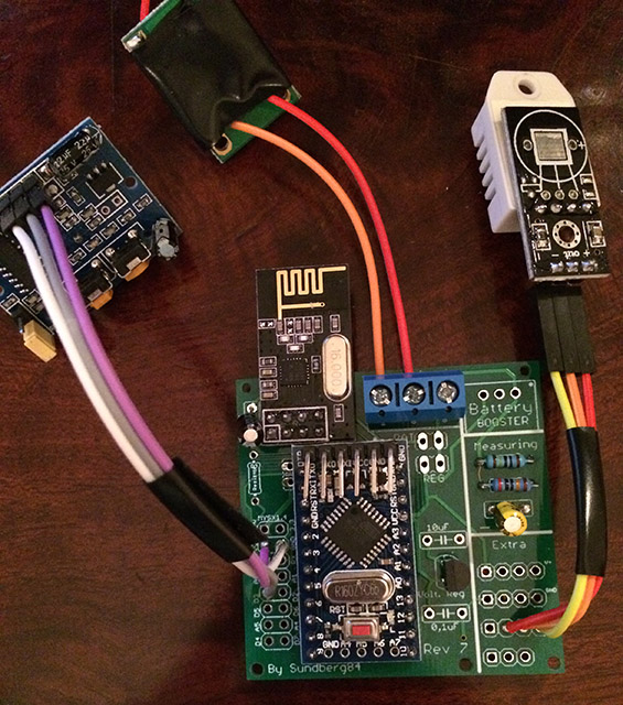
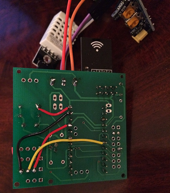
First i used the 5v cable to the raw on the PCB and then it did't work.
When I change to connect to the PWR then it works. Don't know why. Maybe @sundberg84 know why? -
Hi @ErrK.
Work your way backwards with the multimeter. Are you powering with 5v there shouldnt be a drop to 3v. Check volt over arduino and then vcc output. As i said work you way backwards in the circuit.
I suspect a faulty hardware somewhere, measure the input and output on the voltage regulator on the arduino.
-
@Maciej-Kulawik Thanks.
Today my second node started to do this too.
I have tried to change the HC-SR501 and the problem seams to be on the node and not on the sensor.
Can i see how you fixed this in the sketch?@ErrK In my case PIR switches into HIGH for some seconds (depending on potentiometer), so reading after 100ms will give the same value.
@ErrK Unfortunately my solution is not 100% reliable. For 2 of my nodes it works well, but for 3rd node (the same hardware, the same sketch, only PCB is a little bi different - previous version, but difference only in dimension) - pir is false triggerring almost each minute (sometimes with 2 minutes delay with false triggering). And I checked - it is not caused by NRF sending. I have no idea whats going on.
-
@Maciej-Kulawik , how are you powering the node? I had once a PIR false-triggering due power instabilities...
-
Hi,
i'm wanted to share my experience also with those sensor.
I had a lot of issue with false trigger when running on 3.3V. In my case the power was definitely the issue.
it's looks like sleeping the radio/mcu cause some noise on the voltage line.I solve 100% of my false trigger issue when doing a small sleep, before enabling the sleep with interrupt.
gw.sleep(500); gw.sleep(INTERRUPT,RISING, SLEEP_TIME); -
@Maciej-Kulawik , how are you powering the node? I had once a PIR false-triggering due power instabilities...
@rvendrame I'm powering all with 2xAA baterries. On PIR I removed regulator. The problem with false trigerring is independent from voltage level. It is the same if I put old baterries (2,8V) or brand new (3,2V).
@fifipil909 I also suspect that it is somehow connected to powering noises and mcu sleeping. In my one case PIR is triggering each minute - and sleep time is also one minute. -
@Maciej-Kulawik , maybe if you try to power the PIR with +5V for a while and watch the results? Don't forget to keep all GNDs inter-connected...
-
I'm also having this issue at 3V. It gets triggered if there is a (little) voltage drop. All my pirs only wake with an interrupt and no timer, then it works fine. But with a sleep timer it won't work the normal way.
At 5V everything works fine.
Maybe @fifipil909 's solution works.
-
I was testing the below sensor with 3.3v and it was reporting false status. It worked well with 5v. Although the site claims it works between 3 to 5 volts.
Maybe power issueshttp://store.fut-electronics.com/products/pir-motion-sensor-module-adjustable-range
-
I was testing the below sensor with 3.3v and it was reporting false status. It worked well with 5v. Although the site claims it works between 3 to 5 volts.
Maybe power issueshttp://store.fut-electronics.com/products/pir-motion-sensor-module-adjustable-range
@ahmedadelhosni All those PIRs are built using the same chip. All all have 3,3v regulator onboard, so they always work with 3,3v. I don't understand why powering directly with 3,2v from battery makes so trouble.
Maybe this LDO regulator adds some additional stabilisation/filtering on power line, when powered with greater voltage... -
@ahmedadelhosni All those PIRs are built using the same chip. All all have 3,3v regulator onboard, so they always work with 3,3v. I don't understand why powering directly with 3,2v from battery makes so trouble.
Maybe this LDO regulator adds some additional stabilisation/filtering on power line, when powered with greater voltage...@Maciej-Kulawik It can be that the on-board LDO needs more than 3.3v to activate. It maybe even dropping the voltage from batteries, and doing nothing but disturbing :-) Maybe it worth to remove it when running the circuit with 3V from batteries.
-
@Maciej-Kulawik It can be that the on-board LDO needs more than 3.3v to activate. It maybe even dropping the voltage from batteries, and doing nothing but disturbing :-) Maybe it worth to remove it when running the circuit with 3V from batteries.
@rvendrame But I work only with pirs with ldo removed (and diode).
-
@rvendrame But I work only with pirs with ldo removed (and diode).
@Maciej-Kulawik if so, your PIR looks to need at least 3.3V, so the ~3V from 2xAA is not enough and it is causing instabilities (probably the same as reported by others here).
-
@ahmedadelhosni All those PIRs are built using the same chip. All all have 3,3v regulator onboard, so they always work with 3,3v. I don't understand why powering directly with 3,2v from battery makes so trouble.
Maybe this LDO regulator adds some additional stabilisation/filtering on power line, when powered with greater voltage...@Maciej-Kulawik I didnt know that info. Thanks.
-
Did you guys get them working? I tried to power the pir sensor via the "H" pad directly with 3.3V from a boost converter (via a coin cell). Now I get random readings that I didn't have when using a stable 3.3V source. Any ideas how to solve this?
I haven't (yet) removed the voltage regulator on board. Perhaps that might help... -
Hi,
False detection is only due to power stability issue.
Personnaly i remove the regulator and power the PIR without any boost on the VCC pin. Even below 2v the PIR continue working without any a single issue.Did you try to do a small delay before sleeping with interupt ? See my post a bit upper.
For me it solve all my false trigger issue.
Hello! It looks like you're interested in this conversation, but you don't have an account yet.
Getting fed up of having to scroll through the same posts each visit? When you register for an account, you'll always come back to exactly where you were before, and choose to be notified of new replies (either via email, or push notification). You'll also be able to save bookmarks and upvote posts to show your appreciation to other community members.
With your input, this post could be even better 💗
Register Login