Arduino and NRF24 Mesh Code
-
I have seen this NRF24 mesh tutorial of MySensor Library on the link link text but could not find any sample code of it's implementation. Is there any sample code that implements sensor and gateway code.Please help , thanks in advance.
-
I have seen this NRF24 mesh tutorial of MySensor Library on the link link text but could not find any sample code of it's implementation. Is there any sample code that implements sensor and gateway code.Please help , thanks in advance.
@سیدعظیم-عباس there are lots of examples on https://www.mysensors.org/build/
Which type of sensor do you want to build? -
I have 4 arduino uno's with nrf24 and i want to make 3 uno's as a sensor nodes and one as a gateway node.I want to make networking mesh of these 3 sensor nodes and 1 gateway node.
-
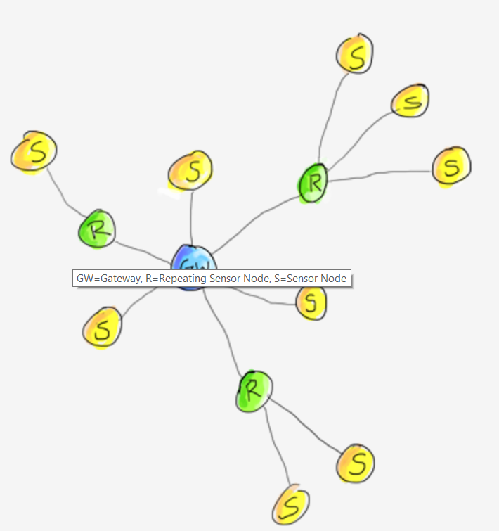
The gateway is always Node 0 and that "target" is coded as default. If you want to go from Node 2 (S) to Node 1 (R) and then to the Gateway (GW) as stated on your painting above, you have to init Node 2 with "target" Node 1 insted of 0 and tell Node 1, that it is a repeater. This is done by create repeating node.
-
#include <MySensor.h>
#include <SPI.h>
#include <Bounce2.h>

#define RELAY_PIN  4  // Arduino Digital I/O pin number for relay
#define BUTTON_PIN  3  // Arduino Digital I/O pin number for button
#define CHILD_ID 1   // Id of the sensor child
#define RELAY_ON 1
#define RELAY_OFF 0

Bounce debouncer = Bounce();
int oldValue=0;
bool state;
MySensor gw;
MyMessage msg(CHILD_ID,V_LIGHT);

void setup()
{
  gw.begin(incomingMessage, AUTO, true);

  // Send the sketch version information to the gateway and Controller
  gw.sendSketchInfo("Relay & Button", "1.0");

 // Setup the button
  pinMode(BUTTON_PIN,INPUT);
  // Activate internal pull-up
  digitalWrite(BUTTON_PIN,HIGH);

  // After setting up the button, setup debouncer
  debouncer.attach(BUTTON_PIN);
  debouncer.interval(5);

  // Register all sensors to gw (they will be created as child devices)
  gw.present(CHILD_ID, S_LIGHT);

  // Make sure relays are off when starting up
  digitalWrite(RELAY_PIN, RELAY_OFF);
  // Then set relay pins in output mode
  pinMode(RELAY_PIN, OUTPUT);

  // Set relay to last known state (using eeprom storage)
  state = gw.loadState(CHILD_ID);
  digitalWrite(RELAY_PIN, state?RELAY_ON:RELAY_OFF);
}


/*
*  Example on how to asynchronously check for new messages from gw
*/
void loop()
{
  gw.process();
  debouncer.update();
  // Get the update value
  int value = debouncer.read();
  if (value != oldValue && value==0) {
      gw.send(msg.set(state?false:true), true); // Send new state and request ack back
  }
  oldValue = value;
}

void incomingMessage(const MyMessage &message) {
  // We only expect one type of message from controller. But we better check anyway.
  if (message.isAck()) {
     Serial.println("This is an ack from gateway");
  }

  if (message.type == V_LIGHT) {
     // Change relay state
     state = message.getBool();
     digitalWrite(RELAY_PIN, state?RELAY_ON:RELAY_OFF);
     // Store state in eeprom
     gw.saveState(CHILD_ID, state);

     // Write some debug info
     Serial.print("Incoming change for sensor:");
     Serial.print(message.sensor);
     Serial.print(", New status: ");
     Serial.println(message.getBool());
   }
}
Thanks for your reply , I have shared the sample code of MySensor Library above according to this code you mean that all the gateway nodes will have child_id 0 and sensor node will have child_id 1.
-
There is always only one gateway. This has to be NodeID 0. NodeID of the for all other nodes are free of choice or assigned automaticly.
ChildIDs are for the children of the nodes: the sensors themself. They are presented to the gateway. -
For example , I am controlling switches of 4 rooms(each room can be consider as a node) , having 6 buttons each when I call MyMessage msg(CHILD_ID,V_LIGHT); and than gw.send how i can assure which button of that node or room i wont to turn.
Also if i am assign child_id as 0,1,2..... in neighbor their can also be nodes having CHILD_ID same. -
The NodeId + SensorId are the adress of that switches, so the same Childs on different nodes are allowed:
- Livingroom Node 10, ChildIds 1,2,3,4,5,6
- Kitchen: Node 20, ChildIDs 1,2,3,4,5,6
you have to present every single one of them. You can use a loop for that like:
#define RELAY_1 3 // Arduino Digital I/O pin number for first relay (second on pin+1 etc) #define NUMBER_OF_RELAYS 4 // Total number of attached relays #define RELAY_ON 0 // GPIO value to write to turn on attached relay #define RELAY_OFF 1 // GPIO value to write to turn off attached relay // for (int sensor=1, pin=RELAY_1; sensor<=NUMBER_OF_RELAYS;sensor++, pin++) { // Register all sensors to gw (they will be created as child devices) gw.present(sensor, S_LIGHT); } }``` -
/**
 * The MySensors Arduino library handles the wireless radio link and protocol
 * between your home built sensors/actuators and HA controller of choice.
 * The sensors forms a self healing radio network with optional repeaters. Each
 * repeater and gateway builds a routing tables in EEPROM which keeps track of the
 * network topology allowing messages to be routed to nodes.
 *
 * Created by Henrik Ekblad <henrik.ekblad@mysensors.org>
 * Copyright (C) 2013-2015 Sensnology AB
 * Full contributor list: https://github.com/mysensors/Arduino/graphs/contributors
 *
 * Documentation: http://www.mysensors.org
 * Support Forum: http://forum.mysensors.org
 *
 * This program is free software; you can redistribute it and/or
 * modify it under the terms of the GNU General Public License
 * version 2 as published by the Free Software Foundation.
 *
 *******************************
 *
 * REVISION HISTORY
 * Version 1.0 - Henrik Ekblad
 *
 * DESCRIPTION
 * Example sketch showing how to control physical relays.
 * This example will remember relay state after power failure.
 * http://www.mysensors.org/build/relay
 */

#include <MySigningNone.h>
#include <MyTransportNRF24.h>
#include <MyTransportRFM69.h>
#include <MyHwATMega328.h>
#include <MySensor.h>
#include <SPI.h>

#define RELAY_1  3  // Arduino Digital I/O pin number for first relay (second on pin+1 etc)
#define NUMBER_OF_RELAYS 1 // Total number of attached relays
#define RELAY_ON 1  // GPIO value to write to turn on attached relay
#define RELAY_OFF 0 // GPIO value to write to turn off attached relay

// NRFRF24L01 radio driver (set low transmit power by default)
MyTransportNRF24 radio(RF24_CE_PIN, RF24_CS_PIN, RF24_PA_LEVEL_GW);
//MyTransportRFM69 radio;
// Message signing driver (none default)
//MySigningNone signer;
// Select AtMega328 hardware profile
MyHwATMega328 hw;
// Construct MySensors library
MySensor gw(radio, hw);

void setup()
{
  // Initialize library and add callback for incoming messages
  gw.begin(incomingMessage, AUTO, true);
  // Send the sketch version information to the gateway and Controller
  gw.sendSketchInfo("Relay", "1.0");

  // Fetch relay status
  for (int sensor=1, pin=RELAY_1; sensor<=NUMBER_OF_RELAYS;sensor++, pin++) {
    // Register all sensors to gw (they will be created as child devices)
    gw.present(sensor, S_LIGHT);
    // Then set relay pins in output mode
    pinMode(pin, OUTPUT);
    // Set relay to last known state (using eeprom storage)
    digitalWrite(pin, gw.loadState(sensor)?RELAY_ON:RELAY_OFF);
  }
}


void loop()
{
  // Alway process incoming messages whenever possible
  gw.process();
}

void incomingMessage(const MyMessage &message) {
  // We only expect one type of message from controller. But we better check anyway.
  if (message.type==V_LIGHT) {
     // Change relay state
     digitalWrite(message.sensor-1+RELAY_1, message.getBool()?RELAY_ON:RELAY_OFF);
     // Store state in eeprom
     gw.saveState(message.sensor, message.getBool());
     // Write some debug info
     Serial.print("Incoming change for sensor:");
     Serial.print(message.sensor);
     Serial.print(", New status: ");
     Serial.println(message.getBool());
   }
}
above i have shared a sample code of RelayActuator can i treat it as one sensor node controlling one relay switch from pin 3.Please guide me i am new to mysensor library.
Hello! It looks like you're interested in this conversation, but you don't have an account yet.
Getting fed up of having to scroll through the same posts each visit? When you register for an account, you'll always come back to exactly where you were before, and choose to be notified of new replies (either via email, or push notification). You'll also be able to save bookmarks and upvote posts to show your appreciation to other community members.
With your input, this post could be even better 💗
Register Login