Relay Node: radio init failure
-
I have two modules:
- Ethernet Gateway w/Clone Nano, W5100 and NRF24L01+
Flashing this module with EthernetGateway.ino and opening serial debug I get this:
0;0;3;0;9;gateway started, id=0, parent=0, distance=0
0;0;3;0;14;Gateway startup complete.
Finished
0;0;3;0;2;0;0;3;0;2;1.5.4
Finished
0;0;3;0;2;Get Version0;0;3;0;2;1.5.4
Finished
0;0;3;0;18;PINGFinished
0;0;3;0;18;PINGFinishedWhich I think means everything is working and the PING is a response to Domoticz request for setup.
- Relay Module w/Clone Mini Pro, NRF24L01+ and 5/3.3 voltage regulator
Flashing the module with RelayActuator.ino and stating Serial monitor I get:
radio init fail
So, after two days of checking power, wiring, re-flowing solder, changing radios and researching issues, I decide to flash the Relay Module with EthernetGateway.ino, since I can't think of anything else to do. Rearranging radio wiring for the EthernetGateway(since it is different) and using the EXACT SAME HARDWARE, I flash it with EthernetGateway.ino and get this:
0;0;3;0;9;gateway started, id=0, parent=0, distance=0
Which I think means the radio is working.
I then reflash the EXACT SAME HARDWARE using the EthernetGateway radio wiring with the RelayActuator.ino and I get this:
radio init fail
Which I expected. All hardware was prototyped and verified to work with Domoticz before soldering onto PCB. Only change was to the Ethernet Gateway Nano which lasted about 3 seconds on the 12V power I had planned to run it with.
Ideas?
- Ethernet Gateway w/Clone Nano, W5100 and NRF24L01+
-
I am working this problem from the prototype board since the relay components are now soldered in and mounted in a case. The same issue exists with each set of components... i.e. soldered in and prototype have the same serial debut outputs.
This is the prototype. I have replaced the leads according to the color coding at https://www.mysensors.org/build/connect_radio for trace-ability. I confirmed that the serial debug responses are the same after the rewire. The cap on the radio power is 10uF, this is all I have. I have also tried 68uF with the same results. Recommendations for the size of this component vary by 4 orders of magnitude across MySensors forum. In my uneducated opinion, cap should not matter for initialization.

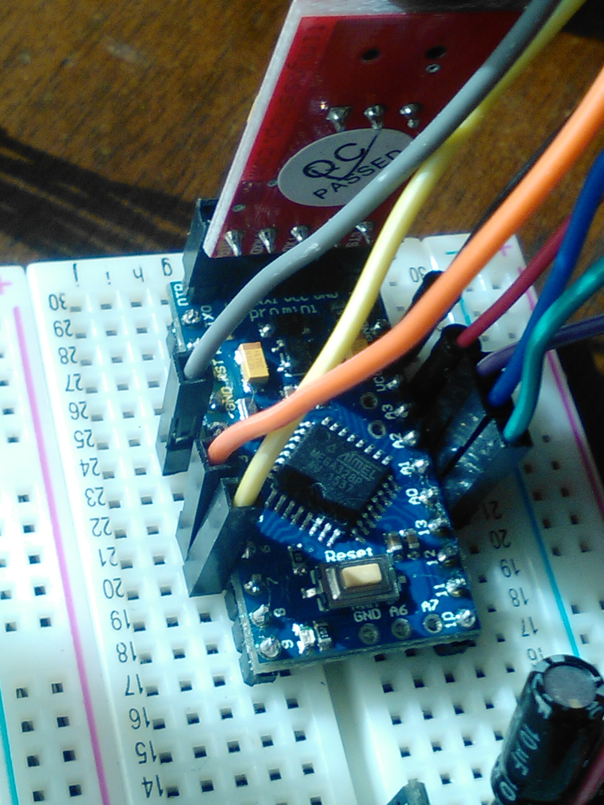
Closeup of the Mini wired for the RelayActuator.ino.
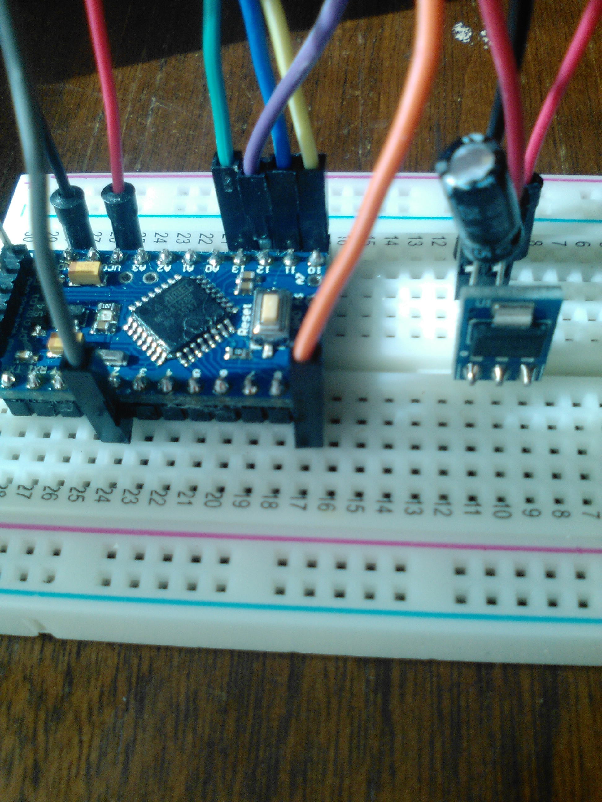
Closeup of the radio connections:
Serial Debug output of this configuration:radio init fail
Mini rewired for EthernetGateway.ino
Enable soft_spi in myconfig.h and flash the Mini with EthernetGateway.ino, this is the Serial Debug output:
0;0;3;0;9;gateway started, id=0, parent=0, distance=0Same hardware... same wires... same power supply... different software and wiring for software.
-
Radio wiring photo crapped out:

I get 405 Error Not Allowed each time I try to upload this image.
Update:18:30hrs
GettingStarted.ino from this site https://arduino-info.wikispaces.com/Nrf24L01-2.4GHz-HowTo runs the radio just fine utilizing the arduino pin hookup TMRh20 RF24 Library. This is looking like a software issue or a pin out error. -
I have 10 radios. Two were prototyped to verify and then soldered into enclosures. Three days ago I could not sleep and decided to work on this issue for a bit. Going over the same steps I have gone over multiple times, suddenly, miraculously, the communications started to work. For 15 glorious minutes I clicked an icon on the computer and the relay operated. Then the clock struck midnight and they turned back into pumpkins! I am not making any of this up.
Of the remaining 8 radios and 4 or 5 arduinos I have used every software library I can find to try to figure this out. None are diagnostic. Each presumes that the radios, arduinos and stars align and they just work OoB. GettingStarted seems to be the most universally used for radio validation. Using this code and the wiring recommended for it, I can get none of the 8 radios to get past these lines of code:
unsigned long start_time = micros(); // Take the time, and send it. This will block until complete
if (!radio.write( &start_time, sizeof(unsigned long) )){
Serial.println(F("failed"));This means to me that none of the radio's and/or none of the arduino's and/or none of the power configurations work.
Respectfully, if this is a wiring issue, then you can tie me up and paint me blue! I will be blue-fully happy to have finally been shown the truth.
-
I have 10 radios. Two were prototyped to verify and then soldered into enclosures. Three days ago I could not sleep and decided to work on this issue for a bit. Going over the same steps I have gone over multiple times, suddenly, miraculously, the communications started to work. For 15 glorious minutes I clicked an icon on the computer and the relay operated. Then the clock struck midnight and they turned back into pumpkins! I am not making any of this up.
Of the remaining 8 radios and 4 or 5 arduinos I have used every software library I can find to try to figure this out. None are diagnostic. Each presumes that the radios, arduinos and stars align and they just work OoB. GettingStarted seems to be the most universally used for radio validation. Using this code and the wiring recommended for it, I can get none of the 8 radios to get past these lines of code:
unsigned long start_time = micros(); // Take the time, and send it. This will block until complete
if (!radio.write( &start_time, sizeof(unsigned long) )){
Serial.println(F("failed"));This means to me that none of the radio's and/or none of the arduino's and/or none of the power configurations work.
Respectfully, if this is a wiring issue, then you can tie me up and paint me blue! I will be blue-fully happy to have finally been shown the truth.
@martrw You sound pretty hopeless... and not even getting past the first step. Have you measured voltages etc. to make sure the radio gets its juice (and not more than 3.5V)? You can test your arduino with a "blink" sketch on all the relevant pins. If all correct I can't think of anything else that a very bad batch of radio's.
Hello! It looks like you're interested in this conversation, but you don't have an account yet.
Getting fed up of having to scroll through the same posts each visit? When you register for an account, you'll always come back to exactly where you were before, and choose to be notified of new replies (either via email, or push notification). You'll also be able to save bookmarks and upvote posts to show your appreciation to other community members.
With your input, this post could be even better 💗
Register Login