💬 MyMultisensors


  • Very beautiful design and, as usual, so interesting !


  • Hardware Contributor

    @carlierd thx. and as usual.. you're very kind, plus I like your avatar 😉


  • Unfortunately it's not me on the avatar but it's my preferred judo technic 😉


  • Hardware Contributor

    Very nice looking project! And someone else who loves judo 😉
    Will you upload your schematics? I am working on a similar (although not as integrated) project and perhaps I can learn some things from your board.


  • Hardware Contributor

    @LastSamurai
    yeah thx, samurai and budo 🙂 On my side, I love Wing Chun kungfu (not wushu!). So Ip Man is one of my favorite movie lol! I practise a little bit JJB and Eskrima too, ; fun is there are cross concepts like triangle and keep/catch the centerline..

    Schematic is already uploaded. I was thinking to upload the other files but I would like to test it before someone try and need me for debug (I will have already enough debug on my side...). Do you need something in particular?


  • I am more a jujitsuka but not JJB. But due to the small number of hours in a day (only 24 😉 ) I spent most of sport time to run ! I started jujitsu too late (34 years), very difficult with people which started at 5 !!


  • Contest Winner

    Cool this is the MySensors martial arts corner 😉 I do Tai Chi Chuan and Tai Chi Sword. The latter I started recently but I'm loving it. We learn the complete form but also sword handling and fighting skills.


  • Hardware Contributor

    @carlierd
    cool 🙂 yep, I miss time too..I'm lucky to have a mookjong near my desk 🙂 so I can make a break when I have a problem in my work! plus our forms don't take lot of place to train, very pratical, when you are in car or waiting somewhere 😆

    @TheoL
    very cool, I hope you enjoy too 🙂 int vs ext? sticking vs pushing hand? direct vs circular? which one is better? none lol! almost same goals, personal style, and finally the fun is it's like playing chess! So the boards I design are always routed with 45° or circular route! no right angle route..nonsense ahah! Be like water my friend 😊

    Now, sorry guys, don't laugh, that's embarrassing, I have to stop this (interesting) OT 😞 I feel like you I could spend my time to talk about this, sport and wellness...but I shoud try to attract openhardware makers than martialart.com !! So what was I saying??? huum..50 years on coincell?.. 😊


  • @scalz : one question about RFM, why RFM69CW and not HW ? And why the 10k resistor between CS and VCC ?

    David.


  • Hardware Contributor

    @carlierd
    the W not the HW. It's because CW is smaller than the W version. They are software compatible.

    For the pullup, it's a good practice to be sure to have the right level on the CS line. you can forgot it sometimes, but sometimes not having it on each cs line can be source of useless trouble..


  • First time I see this resistor ! Will add it in my design. But I need to learn more information on the SPI first.

    David.


  • Hardware Contributor

    @carlierd
    yes I know..and sure the cs line can be output=high in the setup sketch part...
    briefly for spi, you have: mosi (data output of master/mcu), miso (data input), sck (clock sync). and the CS line is active low when you want to select the chip.
    So if for any reason, the CS line is in an unknown state (for instance when mcu reset or other case..), that could give some strange working. And again more trouble, if you have other chip sharing the same spi bus, and no pullup on each CS to give a nice voltage level and choose the right chip..

    Here a nice article: http://www.dorkbotpdx.org/blog/paul/better_spi_bus_design_in_3_steps


  • Will the board be possible to buy assembled?


  • Hardware Contributor

    yep, it's planned. I will try to make this option possible.
    sorry for delay, I have lot of other things in progress. but it should not take too much time before I give more news.


  • Hardware Contributor

    I am very happy because the pir circuit trigger very well, I'm rather impressed. Yeah 😃
    so far, very few tests because I was playing with software on other things but I've tested two different lens as the pir sensor range is mostly dependant of the lens.

    I will give more results. I'm working on it today 😉 I need to boost..tonight no work! it's champions league final 😄


  • Hardware Contributor

    and the interesting thing is power consumption (pir circuit only) : 1.8uA in sleep mode, 2.5uA active, promising 🙂


  • Hardware Contributor

    still working nice for the moment 🙂 I have modified my schematic a bit, removed few useless things, and improved others for power consumption and a bit of miniaturization 😉

    I am working on the software too. to improve power consumption during blindtime etc.

    @hek
    I'm using pinchange in my sketch, for few pins. Actually it's raw, I did it with raw registers too, but that's not user friendly and I have already seen this question. I'm looking to make it mysensors now. I am using the EnableInterrupt lib.
    So if I use the lib with mysensors I get an error "multiple definition of `__vector_2' ". I see that comes from myHwATmega328 part, from "attachinterrupt".

    What do you think about this:

    • a special define like MYS_USE_EXTINT.
    • If defined, in myHwATmega328, in the sleep methods we use the EnableInt lib instead of arduino attachinterrupt
    • keep the isr routines for int0 and 1 handled as it is
    • and for the others isr, in the main sketch so user/I could do what I want in my irq.
      something like this in sketch then,
      enableInterrupt(PIR_INT_PINH, irq_pirh, RISING);
      enableInterrupt(PIR_INT_PINL, irq_pirl, RISING); 
    

    It's roughly explained 🙂 Is it planned or done? Which way do you prefer??


  • Hardware Contributor

    Hi.

    so it's still a wip but I'm getting close of what I want 🙂
    because using a coincell (without regul) is more tricky. due to internal res of coin cell 😉

    An example, the PIR circuit was working nice in standalone (without nothing around, it uses 1.6uA in trigger or not). As soon as I added the atmel chip (and nothing more, no radio at all, no i2c..). Bingo, nice to meet you false triggers!!
    This was the coincell which was making me a joke lol As soon as atmel woke up I got a cycling false trigger yeah. In fact having atmel internal 8mhz is enough power hungry to make a nice voltage drop and the pir trigger.
    So I solved it in sketch, and a bit of hardware too 😉

    I am curious to know if others people playing with coincell will have long lifetime without some optimizations (hardware and software..).

    So now, the actual state for me this week end, is to connect radio and play again. And add some stuff about listenmode and atc to improve overall..

    About my previous post about external int, no more problem, I am using raw registers for external int and sleep function. because I need some custom things. Plus, the more libs and features, the less mem I have and I have not so much space...I will need to disable some debugs lol if I want all my sensors, signing, rfm69 with new mode etc..

    I'm not really surprised, I was expecting a bit this behaviour, that's why I said this would be a nice sketch challenge 🙂


  • Hero Member

    @scalz This is sure to be unwelcome advice, but do yourself a favor by simplifying this project before it drags you down.


  • Hardware Contributor

    @NeverDie saying this you're challenging me lol 🙂 more seriously, I have no real issue.
    what would you simplify? can't be more simple imho. no regulator, just batt.. I still can use 2xaa/aaa. That would ease a bit. the circuit works fine as expected 😉 but that would be less fun without optimizations 😉

    Things I have thought when I did my choice:

    • as the pir analog is sensitive, I wanted no regul for this one. or I would go for a booster and then more hardware debug (I have already a one cell optimized design that I plan to try with this pir, just to know if there will be a rev2 lol..). But that would need more care&filtering with good quality components (shielded inductors, ferrites, capacitors...) to prevent false trigger.
      Like this one I did https://forum.mysensors.org/topic/2951/my-mysx-multisensors-board or my ulpnode clone 😉 That would be an overall more expensive solution. but with less maintenance and one cell 😉
    • use 1uA digital PIR...not cheap
    • use a better mcu like cc1310 with its power domains and events. but not mysensors/arduino.
    • coincell is just for the fun as this design. and like I said I can use 2 lithium or alkaline.

  • Hardware Contributor

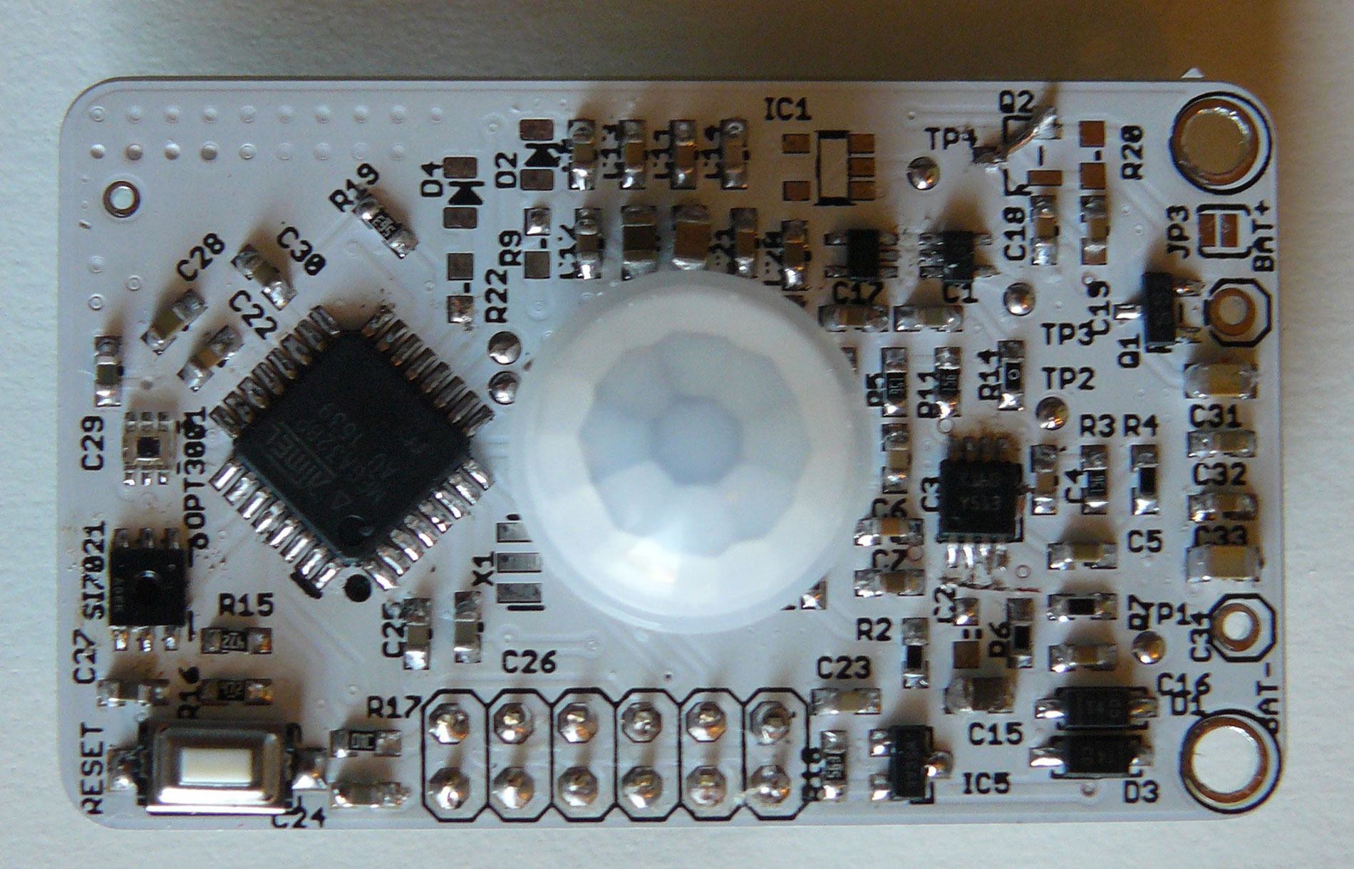
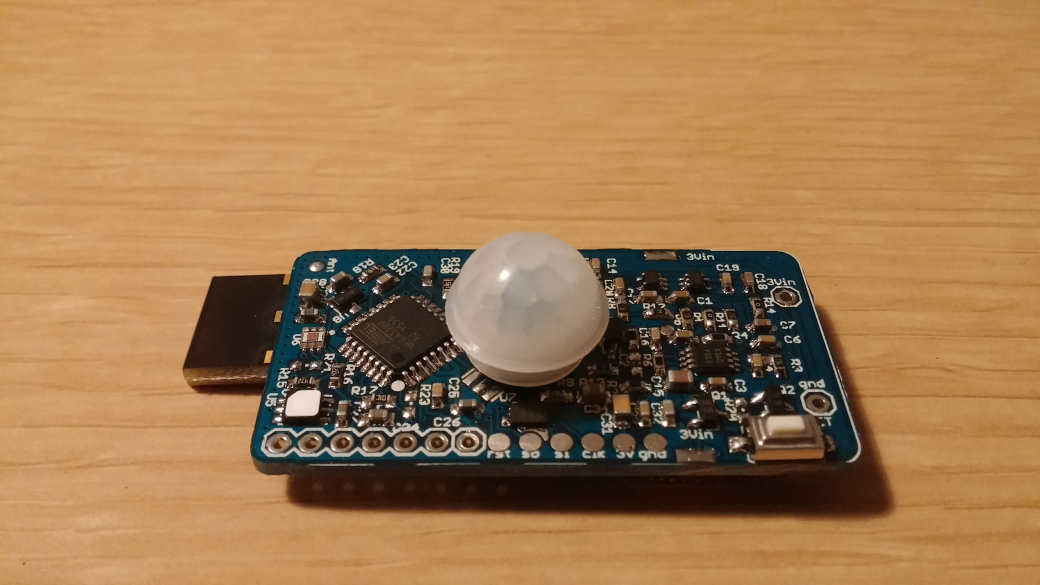
    Few pics of another board i have just assembled. I have just noticed I didn't show any proof/pics 😕

    Top view
    0_1468163835509_MyCoincellMultisensors_t1.jpg
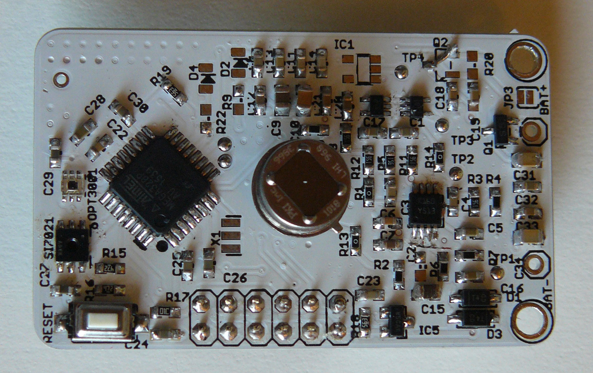
    With this lense, I get 5-6m.
    0_1468163883675_MyCoincellMultisensors_t2.jpg
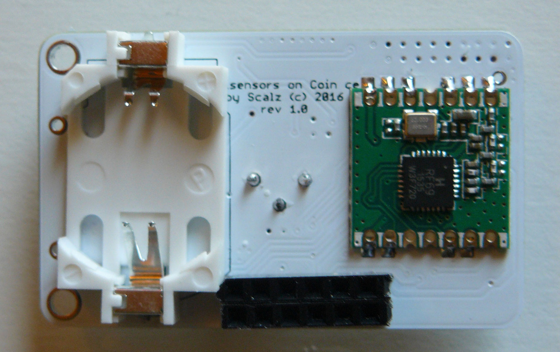
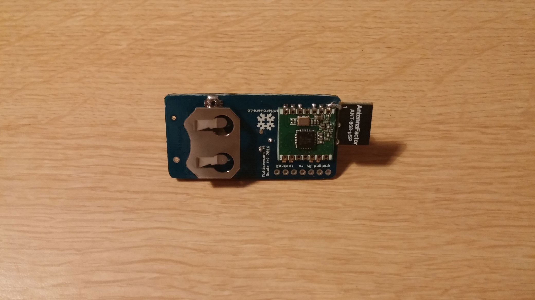
    Bottom view, with rfm69, coincell holder and AVRSPI/FTDI connector.
    0_1468163920031_MyCoincellMultisensors_b1.jpg

    I am waiting for rev 1.1 pcb. No big changes, I improved a bit silkscreen, removed the schmitt trigger to save some power and in place i use pinchange int, makes more sense. Few routes and size changed.
    Though, 328p is memory limited, I have to disable debug for this one!


  • Hardware Contributor

    nothing fancy, just wanted to share how this is working as we're all busy..

    there is a small problem with my widgets but no matter 😊 I show you what this board outputs if you're curious, and I'm beginning to like this board 😍

    0_1469402151633_dash_multisensor.jpg

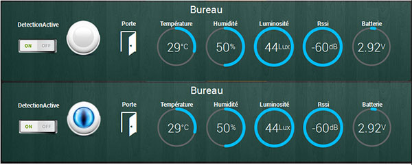
    I will change my dashboard later, it's just for fun.

    For power consumption, few reference for sleep time : old VC506 multimeter but working well + uCurrent Gold

    • PIR enabled, other sensors+MCU in deep sleep with interrupt on pins : 4-5uA for Varta CR2032 coincell, 3-4uA for 2xAAA Duracell
    • PIR enabled, other sensors+MCU in deep sleep with interrupt on pins + WDT enabled : 11uA for the coincell, 8uA for 2xAAA
    • PIR enabled, MCU active 1Mhz, other sensors sleeping with interrupt on pins + WDT enabled : 730-740uA for both

    not that bad 🙂
    I have an other proto waiting (for fun because i do not really need it lol). it's another version not for coincell, but as thin and much smaller! with ota back. I thought for coincell, ota or chain tx pulse, was a bit too much battery killer..even if CR2450 imho...and with our preferred lib 🙂 there are multiple chain tx for presentation, some signing stuff etc..and you can't pause this to limit internal resisitance of the coincell..

    The sketch is still in progress. I mean it's working of course, but still looking to improve a bit things..but i can show you the infos and commands which are available for the controller. That should help to save enough power I think:

    
    // For controller. CHILD_ID are presented. CMDID are not presented to not charge radio tx. But are available from controller, using receive()
    //  CHILD NODE ID/CMD           ID    Description
    #define CHILD_ID_PIR            1     // PIR sensor 
    #define CHILD_ID_TEMP           2     // Temperature sensor
    #define CHILD_ID_HUM            3     // Humidity sensor
    #define CHILD_ID_LIGHT          4     // Ambiant light Child node ID
    #define CHILD_ID_BATT_SENSOR    5     // Battery voltage, % is reported by sendbattery stuff
    #define CHILD_ID_RSSI           6     // Radio rssi
    #define CHILD_ID_DOOR           7     // Door reed switch
    #define CHILD_ID_PIR_EN         8     // Enable PIR 
    #define CMID_FULL               10    // Command from controller with all params below in one tx. below is more for debug..
    #define CMID_PULSES             11    // Command from controller to set PIR number of pulse for windows time 
    #define CMID_WINDOWTIME         12    // Command from controller to set PIR window time   
    #define CMID_BLINDTIME          13    // Command from controller to set PIR blind time   
    #define CMID_CANCELTIME         14    // Command from controller to set PIR cancel time
    #define CMID_EN_LIGHT           15    // Command from controller to enable Light sensor threshold 
    #define CMID_LIGHT_MODE         16    // Command from controller to set Light sensor special mode (for instance, enable pir at certain light level only...) 
    #define CMID_LIGHT_H            17    // Command from controller to set Light sensor high threshold 
    #define CMID_LIGHT_L            18    // Command from controller to set Light sensor low threshold 
    #define CMID_LIGHT_DELTA        19    // Command from controller to set difference of lux for update controller 
    #define CMID_TRANSMIT_INTERVAL  20    // Command from controller to set time between sensor updates
    #define CMID_TH_DELTA           21    // Command from controller to set difference of temp/hum for update controller 
    #define CMID_EN_LED             22    // Command from controller to set led
    

    See you soon 🙂


  • Hello,

    Very complete board !

    How did you report RSSI ? It is RSSI of the node or the gateway ?

    David.


  • Hardware Contributor

    @carlierd hello. hehe yep a bit complete, very memory ric-rac limited 🙂 It's rssi of the node tuned by ATC 😉 I have modified libs, but i'm late on pr...sorry


  • @scalz I will wait. I am curious to see the result on my nodes !


  • Hardware Contributor

    Yo,

    for those who have not seen my latest rev..apologize, I'm working hard to release all my stuff 😉
    It's still working well btw. this is the revision i will release i think (i have few other nice iteration but that's enough!).
    0_1474116844076_20160915_212045.jpg
    0_1474116860159_20160915_212143.jpg

    • Size is 25mmx49mm (same size as a nodemcu)
    • Same specs as before, plus OTA. So optimized for very low power and coincell management. Temp/hum/pir/lux/contact door input
    • Thickness depends on the battery used. That's great as now it's possible to use different kind of battery holder 🙂 CR2032 for the thinnest (8mm without PIR) very thin!, CR2450, or through hole 2xAAA holder
    • you can see a test I want to try: a special antenna i saw on the forum. I will compare it with straight wire antenna, and coiled wire antenna.

    See you soon 🙂


  • Hardware Contributor

    another little pic 😋
    0_1474568971435_20160922_170105.jpg
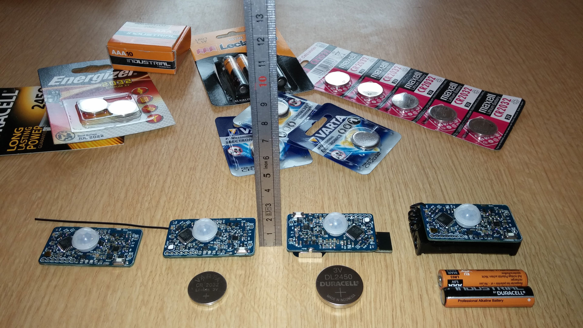
    left to right: 1) pcb without holder, 2) with cr2032 holder, 3) cr2450, 4) 2xaaa
    different antenna format, i have not compared yet. But the straight one, if i remember well, reached 40-50m range with one brick wall (All are the low power version of rfm69, CW). As you can see the coiled antenna (4) does not take so much place compared to the 1.9€ special ant (3).
    I can cover a nice range of use, yeah 🙂


  • Very good job !

    When will share the schematic ?
    How is responding the PIR ?

    And off course, how is the battery usage ? So many sensors could discharge it faster ...

    David.


  • Hardware Contributor

    Hi @carlierd

    i'll fix this! There is still my first version i posted there, on the old topic, https://forum.mysensors.org/topic/3600/my-other-pir-multisensor-on-coin-cell

    PIR is repsonding well, depending of the sensitivity i set in sketch. same for batt!
    Many sensors but all low power 🙂 Except reed switch option, of course my power consumption results above are without reed switch. If i need it, i use a 1M res min (increase a few uA).

    see you soon


  • Contest Winner

    This looks good!
    @scalz The PIR parts, are they based on the app note I showed you way back? 🙂


  • Hardware Contributor

    @anticimex almost! in fact i noticed that's mostly the same schematic if you look at different source. of course it's a PIR ! Regarding the app note you showed me, resistors, capa values changed, and not same ref of comparator (lower power consumption here). so it's very low power 🙂


  • Would it be possible to buy it pre-assembled soon?


  • Hardware Contributor

    Hi.

    yes i'm preparing files for the fabhouse.
    As you can see i've done a little update on my description, i'm focusing on my "work in progress" stuff to "released" at openhardware because i would like to release my others boards etc. and have my mind free for software. That will be hard for a pcb addict like me 🙂
    I hope we'll get a reasonable price..This will be a project for contributing to Mysensors project 😉


  • Hero Member

    @scalz
    Which enclosure do you recommend to go with it?


  • Hardware Contributor

    @NeverDie
    3d printed box for a tailored stuff. I'll also upload .stl and design files. i'm looking at which parts can be "DP" on my BOM, for the pcba..


  • Hardware Contributor

    Hi,
    is it possible to get the actual sketch ?


  • Hola,
    Very nice, I order PCBs.
    I have a question which size for the resonator 8Mhz X1 ?
    By Advance thanks,


  • Hardware Contributor

    hi.
    i've updated the bom. you can use CSTCE8M00G55-R0.
    it's optional, you can omit it if you want, and use internal 8mhz


  • @scalz Thanks !


  • Hardware Contributor

    Hi, which tool do you use for programming with your pogo pin avr isp ?

    Why didn't use pogo pin for FTDI too ?


  • Hardware Contributor

    you can also use pogopin for ftdi, why not 😉
    for avrisp, i use an usbasp.


  • Hardware Contributor

    @scalz Thx but how do you connect your USBASP on the pogo pins ?
    I use an usbasp like this http://d1gsvnjtkwr6dd.cloudfront.net/large/AC-PG-USBASP_LRG.jpg but i don't see how to connect him on the pogo pins 😉


  • Hardware Contributor

    nothing fancy..with dupont cable.
    of course you won't connect the pogo directly on the usbasp.
    make a small adapter. simple and cheap 🙂
    Example with ftdi adapter
    0_1482922538752_ftdi_pogo.png


  • @scalz Awesome board, really. However, I'm a bit worried about its practical use. You see, the motion sensors are commonly placed near the ceiling or sometimes on the ceiling. This may induce a serious drift in the reported temperature. Ideally, a temperature sensor should be placed in the middle of the wall.
    Some people would have the impression that they're wasting energy on heating during winter while others would boost their A/C units during the summer just to read they temperature they feel confortable with. This effect would be mitigate by either concealing the motion sensor at a proper height for temperature reading, or use a reference sensor for calibration and compensate the reported value of an improperly placed sensor, and that's assuming that the seasonal variation is linear.
    Anyway, excellent SMD work, I'm still in the PTH ice age 😀


  • Hardware Contributor

    @mihai-aldea
    thx 🙂
    of course i won't use temperature/hum sensor on the ceiling. Boards are small i can put them everywhere i want.
    On my side, i just need one temp/hum/lum per room, and at least one PIR. This board needs to be well placed of course.
    But if i need more PIR only, or temp/hum only... it's also possible. So i don't need to have a dedicated pcb per use. I stencil only what i need 😉


  • I guess ordering the pcb will only get me the pcb. I need to do the soldering etc myself ?
    But I really wonder how to solder such a board seemingly being smd soldering. Are there any guides available for someone like me (pretty handy, but not experienced in this hardware stuff) ?
    Thanks !


  • Hero Member

    @Sander-Teunissen said:

    I guess ordering the pcb will only get me the pcb. I need to do the soldering etc myself ?
    But I really wonder how to solder such a board seemingly being smd soldering. Are there any guides available for someone like me (pretty handy, but not experienced in this hardware stuff) ?
    Thanks !

    @hek
    Speaking of which, I thought there were going to be some mysensors manufacturering partners who would actually make this stuff, including the soldering. When is that going to happen?


  • Hardware Contributor

    i've been so busy during december, i'll be back for the new year 😉

    About pcba (assembling), it's already possible to use partners in your openhardware account. They may ask for more details if projects need it.


  • Hero Member

    @scalz
    Would they actually make a quantity 1?


  • @scalz said:

    But if i need more PIR only, or temp/hum only... it's also possible. So i don't need to have a dedicated pcb per use. I stencil only what i need 😉

    Yeah, makes sense, a modular sensor PCB, a more advanced version than my Si7021 / DS18B20+ or PIR / door-window PCBs.


  • Admin

    @NeverDie

    PCBWay have quoted a few fully assembled boards on openhardware.io but the prices is pretty high as they won't stock/produce larger batches.

    It's a bit problematic to get low price at low volumes (and low financial commitment).

    I suggest hardware contributors to setup some cooperation directly with the manufacturers. You should have a direct channel to them in the closed manufacturing forum here (accessible for all open hardware contributors).


  • @hek Have you considered using the Seeedstudio PCB assembly service? I haven't tried this service as all my PCB's are using old school PTH. But will try them at some point. It says that "Assembly Fee Starts from $25" but there's no mention whether it's a flat fee or it includes some components assembly. The pricing information is rather fuzzy and I wasn't needing the service for time being anyway so I didn't ask.


  • Admin

    Yes, Seeed Studio have access to quote assembled boards (since a couple of weeks back) on openhardware.io, but they haven't so far as it is a bit more complicated (time consuming) to get a accurate price.

    @scalz and I have been in contact with Seed about this particular board. But we've not had time to follow up on some of their documentation requirements.


  • Hardware Contributor

    @scalz said:

    I stencil only what i need 😉

    I know it's a probably a bit late now, but have you considered making a separate board only for the PIR ?
    Then the "main" board with other sensors would be (relatively) easy to solder and cheap to produce by PCBA, then people could order the PCBA of the PIR only separately if they need.

    And it would be pretty useful for every other board maker on this forum also as a low power PIR is not a real option 😄
    I'm thinking about stealing your design to make a dedicated PIR child board, but I'm afraid my routing skills and electronic knowledge are not good enough yet to make a stable solution that will not be rigged by false detection problems 😞


  • Hardware Contributor

    @Nca78
    My best wishes for the new year 🙂

    I designed this little pir sensor board last month with an optional lux sensor which i think is a nice sensor associated with a PIR. I will post files soon (I'm recovering today, phew!)
    https://www.openhardware.io/view/292/Motion-And-Lux-Shield-V1
    I also derivated it with MYSX connector, so it could be plugged on some new neat sensebender mk for instance 🙂

    And i've asked a pcba for this sensor board, for curiosity. but i've been busy during december.. let's see what we'll get 😉

    But about MyMultisensors. I've designed V2 last month. I didn't need it..just because i wanted to try.
    I've improved cost, changed PIR strategy, new mcu, still low power, and size is 30.5x25.5 ! with all sensors, and a new thing too. I stop talking.I should get the pcb soon and i'll show. .
    Also, that will be a time2time work on the software part because of the mcu choice.


  • Any news about the enclosure ? Or did i miss a comment


  • Hello, this is really an excellent sensor!
    I would like to buy the components for this project, but I do not know which to choose precisely: when I am looking for a capacitor 100n pack 0603 I have 16 V, 20 V, 15%, 20% etc ...
    Do you have a list of references to help us?
    Thanks !


  • Hardware Contributor

    I'll put stl for box soon, i need to check few things, and i'm busy.

    As i've no time for the moment to upload a complete list with manufacturer parts etc.. it's a 3.3v board without regulator, so with passive >6V (for the 100uF for instance) you should be fine. So for others, 16v etc is enough. Rule i use in general, is 2x what my boards need 😉


  • Thanks, and is it OK if I buy 16V for the passive too ?
    Like this one http://www.conrad.fr/ce/fr/product/457889/Condensateur-cramique-CMS-0603-Kemet-C0603C104K4RAC-01-F-16-V-10-X7R-1-pcs?ref=searchDetail for the 100nF for instance.


  • Hardware Contributor

    Yes it's OK to buy 16V. And it should be a rule to buy x7r, so you should be good with those.
    But for big values capacitors (used as power reserve), try to take as low voltage as possible on your circuit as leakage is proportionnal to rated voltage.


  • Thank you so much, so I will buy 16V for 1u capacitor or more, and 6.3V for others.
    And is there a rule for active ? (Watts, volts, amps...)


  • Hardware Contributor

    @particle said:

    Thank you so much, so I will buy 16V for 1u capacitor or more, and 6.3V for others.

    No, it's the opposite 😄
    The higher the voltage rating, the more leakage/losses you will have. It's not important for small capacitors, but for reserve capacitors like 100µF it's better to take as low as possible, basically 2x the voltage used on your board.
    Honestly it's not a big issue if you use 16V instead of 6V, but with a board as optimized for battery life as this one, it would be sad not to optimize the capacitors also 😉


  • OK understood, it's clear now ! 🙂
    And yes with the optimization work, I would like to pay tribute to him!
    And is there a rule for active ? (Watts, volts, amps...)


  • Hardware Contributor

    Hey!

    Sorry for being so late, too much pending projects 🙂

    but here is how looks the custom box for my project. I need to polish a few things, especially sort of mounting plate, then i'll release my stl.

    Box is 62x29x 11.6mm
    No nails no screws.
    i don't like to search my screwdriver or needing screws, or a shorting circuit screw.. So when i can i prefer snaps!

    0_1486292646968_Assembly_multisensors_b.PNG

    And in real

    0_1486292675023_20170205_115515.jpg

    0_1486292691253_20170205_115658.jpg

    See you soon!


  • Hardware Contributor

    @scalz Very good work dude ! What about de V2 ? because i want to build this awesome node but i have read somewhere, you are working on the V2 😉


  • Hardware Contributor

    oki.
    v2 won't be released soon (not this month sure) because i miss time, also it's not mysensors compatible yet. and not rfm69 too 😉


  • Hardware Contributor

    @scalz Oki. And for the nrf24 version ? 🙂


  • Contest Winner

    Unfortunately this circuit and pcb contain a little mistake in reverse polarity protection module. Q1 must be connected as on the following diagram
    reverse polarity
    So just reverse connections of drain and source of Q1, and the next version of your board will contain correct reverse polarity protection 😉
    PS
    Otherwise your circuit will be powered through mosfet body diode (with a drop to ~0.6V of course) when polarity is crossed. 😧


  • Hardware Contributor

    @Koresh thx for feedback 👍 Files are now updated and added a note

    @tonnerre33 sorry for late reply. yes this will be nrf24 compatible, not rfm69. i'll try to show something soon, time does not help me!


  • Hardware Contributor

    @scalz nrf24 for the V1 or V2? Because if V2 isn't mysensors compatible, i prefer use V1 but in nrf24 version 😉


  • So there is no option yet to order complete boards with components in place from manufacturarer? Or am i not getting openhardware correct. Order 10 PCBs will just get me the pcb right?


  • Hardware Contributor

    @Yeitso you are right, 10pcbs order will just give you the pcb 😉


  • Hardware Contributor

    I'm finalizing the nrf24 version because it's a nice board, that would be too bad for nrf24 user

    Did you finish the nrf24 version @scalz ?


  • Hardware Contributor

    @tonnerre33 sorry for delay. yep, sure i finished it a while (rev 1.1 nrf), never ordered it, i use rfm for this node. but i'll upload this week oki


  • Hardware Contributor

    @scalz Thx a lot ! I tried to replace the transmitter myself but the routing is too hard for me.

    I'll try to check the schema before order the board 😉


  • This looks like an awesome unit! Is there a way to buy this with components assembled? Looks like a lot of work to solder all those smds..


  • I also wish I could buy assembled ones.


  • Likewise, to be able to buy assembled would be great


  • @scalz hi, excellent sensor! Do you know if the atmega328 memory is enough? You must have a large sketch for all sensors + signin


  • Hardware Contributor

    @alexsh1 thx 🙂
    memory ok if sketch optimized (radio driver footprint too) and without much debug msg.
    V2 will improve memory, cost and device size (will be 9in1 this time so i needed more mem) but for nrf24 networks only. i should release it soon if i can get rid of a little sw bug..


  • How long can you get these running on a single battery?


  • Hero Member

    @scalz Would also be very interested in buying assembled modules. But why no more RFM69?


  • @mpp I suppose depends on which battery and what sensors - there are a few options here.


  • @scalz atmega328 is only good for simple sketches nowadays. I am struggling with a simple temp/hum/baro sensor with signing and debug as It runs on low memory and the sensor freezes after a few hours. I suppose we have to move to SAMD.
    Do you have the STL file for the box please?


  • Contest Winner

    @alexsh1 regarding low memory problems, debug is intended for just that; debug. Once deployed, you can disable debug to ensure the longevity of your program. Probably the sketch eventually dies due to stack shortage.


  • @Anticimex Completely agree. Having said that I have a few nodes where I left debug purely for convenience. I do not want to re-flash the node to debug it in case need be. Right now I am in the process of changing the GW and may need to see node's debug.


  • Hardware Contributor

    @alexsh1
    I agree with you about 328 and 8bits. And that's a while i've done a board for these 😉
    I won't use it in v2 though, tiny 9in1... not possible!
    I also have custom SAMD boards, missing time to release those one too, but imho these mcu are not ultra low power (SAML is).

    I'll publish stl this week..


  • @scalz ATSAM D21 is already compatible with MySensors, whereas ATSAM L21 may be in the pipeline. So for now, we all are stuck with SAMD.

    Looking forward to your stl


  • Phenomenal!

    I have a stupid question.. clicking buy on the page.. what exactly does that buy you>?


  • @Konrad-Walsh You buy PCBs (10 0r 15 of them).


  • I am sorry.. I should have been more clear...
    When you say PCB.. Is that a fully assembled product with all the mentioned sensors? Or is it a board and you add sensors to it..

    Please excuse my ignorance


  • @Konrad-Walsh Click on the link and see it yourself 😉
    PCB means a bare board and not a ready product. You have to procure parts and assemble it.


  • @alexsh1 Thank you


  • @Konrad-Walsh said in 💬 MyMultisensors:

    you

    No problem.

    @scalz There is a lot of interest from others to have an assembled sensor. Maybe as a suggestion, you would be interested talking to Itead or similar guys to get it arranged?
    Personally, I am comfortable assembling an SMD board down to 0605 (though it is more difficult with the fan). My preference would be 0805 and up


  • Hardware Contributor

    thx for the interest though 🙂
    for the moment, the quotation i got was not so great imho.. oki i'll try again with other fabhouse for this one 😉 as v2 will cover nrf only


  • Hardware Contributor

    @scalz could you give an idea of the price ? I'm curious 🙂


  • Where might I find the source code?


  • @Carywin a source code for what? There are many combinations of sensors.
    I am sure @scalz can help 🙂


Suggested Topics

0
Online

11.2k
Users

11.1k
Topics

112.5k
Posts