Radiator booster (heating)
-
Winter is cold and energy consumption going up. Time to get out of my cave and start a new project ;-).
Low temperature heating systems use special radiators which can be benficial also for other heating systems.
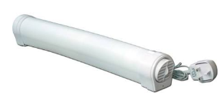
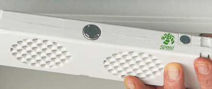
With a few PC vents I built a radiator booster to increase yield of my existing radiators. Still in research stage but results are promising. There are a few commercial options but these are either sub-optimal, expensive and not MySensorized:-1:

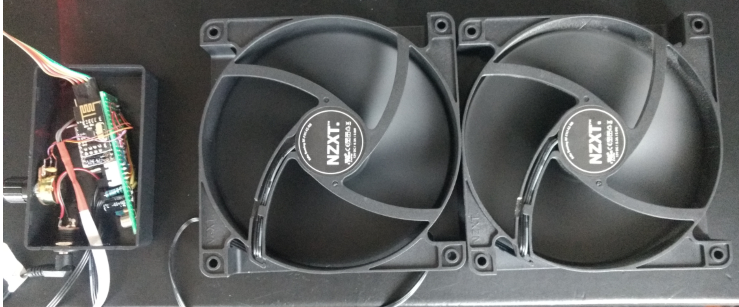
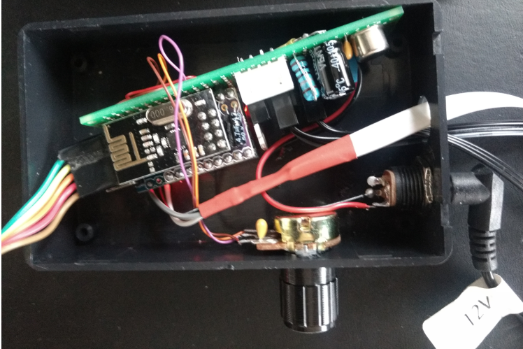
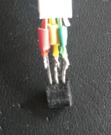
The workbench example built around a compact MySensors node jModule three Dallas temp sensors and PWM circuitry. The whole thing lives in or under the radiator.
Working principle:
- Measure temperatures for water in/ out and environment.
- Vents start spinning slowly as the "In" temperature reaches a threshold (30 Celcius for now)
- Vent spinning increase in time for a few minutes and then slowly spin down until constant level.
- Vents stop spinning when temperature falls below threshold.
- etc.
Extra options:
- Manual mode, started automatically when (MySensors) controller takes over.
- Fan speed control for tuning
I am curious if anybody has some hands-on experience on how to best tune the system. And will publish details (sketch) if anyone is interested.
-
Winter is cold and energy consumption going up. Time to get out of my cave and start a new project ;-).
Low temperature heating systems use special radiators which can be benficial also for other heating systems.
With a few PC vents I built a radiator booster to increase yield of my existing radiators. Still in research stage but results are promising. There are a few commercial options but these are either sub-optimal, expensive and not MySensorized:-1:


The workbench example built around a compact MySensors node jModule three Dallas temp sensors and PWM circuitry. The whole thing lives in or under the radiator.


Working principle:
- Measure temperatures for water in/ out and environment.
- Vents start spinning slowly as the "In" temperature reaches a threshold (30 Celcius for now)
- Vent spinning increase in time for a few minutes and then slowly spin down until constant level.
- Vents stop spinning when temperature falls below threshold.
- etc.
Extra options:
- Manual mode, started automatically when (MySensors) controller takes over.
- Fan speed control for tuning
I am curious if anybody has some hands-on experience on how to best tune the system. And will publish details (sketch) if anyone is interested.


-
@Andrej_AB I think this sketch is doing the job. There are some things to take into account:
- You can comment out the line
#define SPEED_CONTROL_PIN A0 // connect to potentiometer for speed controlif you don't want to have manual speed control. - If you use a PMW fan (4 wire) you need to adjust the PWM frequency to something near 25kHz. ~32 kHz works for me (see sketch) but some fan's are more sensitive.
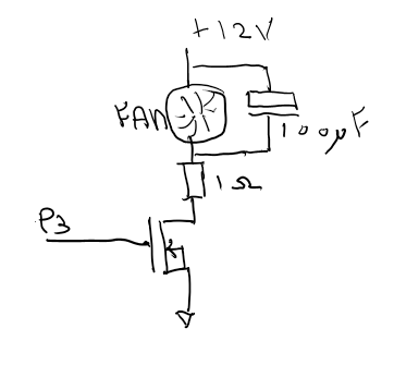
- You can control a non-PWM fan (2 or 3 three wire) with an external MOSFET. In this case you need to lower the PWM frequency to keep a brushless motor in control. ~31 Hz (see sketch) worked for me with the circuit below (sorry for the quality of the drawing ;-). MOSFET is IRLZ44 or almost any other.
- Be aware that I changed the transmission channel / set a fixed node/ set a fixed parent for my own network
/*
 PROJECT: MySensors / Ventilator control
 PROGRAMMER: AWI
 DATE: february 2, 2017/ last update: february 5, 2017
 FILE: AWI_Radiator_Booster.ino
 LICENSE: Public domain

 Hardware: MySensors 2.0, MOSFET dimmer, Dallas temperature

 Special:

 SUMMARY:

	Full independent with manual mode
	Controls ventilator speed with PWM
	Measure temperature and change speed accordingly

 Remarks:
	Fixed node-id

 Change log:
 20170202 - Created from Ventilator control
 20170205 - Clean code and change manual mode
*/

// Enable debug prints to serial monitor
#define MY_DEBUG
#define MY_PARENT_NODE_ID 0
#define MY_NODE_ID 91											// fixed node number
#define NODE_TXT "Radiator Boost 91"							// Text to add to sensor name
#define MY_BAUD_RATE 19200
// Enable and select radio type attached
#define MY_RADIO_NRF24
#define MY_RF24_CHANNEL 83										// 83, radio channel, default = 76

#undef MY_REGISTRATION_FEATURE									// sketch moves on if no registration

#include <SPI.h>
#include <MySensors.h>
#include <OneWire.h>
#include <DallasTemperature.h>

#define ONE_WIRE_BUS 4 											// Pin where dallas sensor is connected
#define MAX_ATTACHED_DS18B20 3
#define TEMPERATURE_PRECISION TEMP_12_BIT
#define IN_THERM 0 												// indexes of in thermometer, adapt to you situation
#define OUT_THERM 2
#define ENV_THERM 1

#define VENT_PIN1 3      										// Arduino PWM pin attached to MOSFET Gate pin -or- vent PWM pin (adjust PWM-Frequency)
#define VENT_MIN_LEVEL 20										// lowest pwm level for vent
#define VENT_MAX_LEVEL 255										// highest pwm level for vent

// #define SPEED_CONTROL_PIN A0									// connect to potentiometer for speed control, if commented out no speed control

#define IN_TEMP_CHILD	0										// measure incoming water temp
#define OUT_TEMP_CHILD	1										// measure outgoing water temp
#define ENV_TEMP_CHILD	3										// environment
#define VENT_CHILD	2											// ventilator

// Helper for Debug:  1 = Serial debug output ; 2 = V_TEXT remote output ; else no debug
// Use Formats described in fprint() : http://www.cplusplus.com/reference/cstdio/printf/
// Example: 	Printf("Temp %2d Hum %2d\n", temperature, humidity);
// warning: max print size < 24 ; float = NOT supported in Arduino, you need to convert it yourself, ie. dtostrf(Temperature, 5, 2, tempBuf)
#define _DEBUG 1												// 0 = no output ; 1 = Serial debug output ; 2 = V_TEXT remote output
#if _DEBUG == 1													// Serial output
	char printBuf[24] ;											// need temporary buffer
	#define Printf(...) { sprintf(printBuf, __VA_ARGS__) ; Serial.print(printBuf);}	// macro to substitute Printf()
#elif _DEBUG == 2												// if remote debug you need to define a child and present it to the controller
	#define DEBUG_CHILD_ID 10									// Child id of V_TEXT
	MyMessage debugMsg(DEBUG_CHILD_ID, V_TEXT);					// get the debug message ready
	char printBuf[24] ;											// need temporary buffer
	#define Printf(...) { sprintf(printBuf, __VA_ARGS__) ; send(debugMsg.set(printBuf)); }	// macro to substitute Printf()
#else															// No debug wanted
	#define Printf(...)
#endif

const unsigned long heartbeatInterval = 1 * 3600UL * 1000UL ;	// heartbeat, let the controller know its alive
unsigned long heartbeatCounter = 0 ;

const unsigned long updateInterval = 10 * 1000UL ;				// controller update
unsigned long lastUpdate = 0 ;

const unsigned long manualTime = 60 * 60 * 1000UL ;				// manual timer exit to automatic if not reset by controller command reception
unsigned long manualTimer = 0 ;
boolean manualFlag = false ;									// flag for boost machine to indicate manual operation
boolean manualStatus = false ;									// actual status of automatic/ manual

const unsigned long boostTime = 30 * 60 * 1000UL ;				// boost timer: period boost is active
unsigned long boostTimer = 0 ;
boolean boostStatus = false ;
const uint8_t boostTemperature = 30 ;							// temperature on which boost becomes active in Celcius
const uint8_t boostThreshold = 2 ;								// threshold for temperature in Celcius

const uint8_t maxVentLevel = 0xFF ;								// level in max boost
const uint8_t minVentLevel = 20 ;								// level in min boost
const uint8_t runVentLevel = 50 ;								// level in running state (rest)

const unsigned long dimLevelInterval = 10UL ;					// dimlevelinterval
unsigned long lastDimLevelUpdate = 0 ;

uint8_t lastDimLevel = 0x0 , newDimLevel = 0x0	;				// Current or last dim level...

// flags to indicate if transmission is needed, heartbeat and/or changes > treshold
boolean txTemperature = true ;									// flags to indicate if transmit is needed (time / change driven)
const float tempThreshold = 0.01 ; 								// send only if change > treshold (Celcius)

// arrays to hold device addresses and last temp
DeviceAddress dThermometer[MAX_ATTACHED_DS18B20];				// hold addresses
float lastTemperature[MAX_ATTACHED_DS18B20];

OneWire oneWire(ONE_WIRE_BUS); 									// Setup a oneWire instance to communicate with any OneWire devices (not just Maxim/Dallas temperature ICs)
DallasTemperature sensors(&oneWire); 							// Pass the oneWire reference to Dallas Temperature.

MyMessage dimmerMsg(0, V_PERCENTAGE);
MyMessage lightMsg(0, V_LIGHT);
MyMessage temperatureMsg(0, V_TEMP);							// Temp

/***
 * Dimmable LED initialization method
 */
void setup(){
	// Set PWM for vents, PWM 4 wire vents needs 25kHz, PWM 3 wire (voltage controlled) need low frequency PWM < 100 Hz
	// comment out frequency here. (https://arduino-info.wikispaces.com/Arduino-PWM-Frequency)
	pinMode( VENT_PIN1, OUTPUT) ;
	TCCR2B = TCCR2B & B11111000 | B00000001;    				// set timer 2 divisor to     1 for PWM frequency of 31372.55 Hz
	//TCCR2B = TCCR2B & B11111000 | B00000110;    				// pin3, set timer 2 divisor to   256 for PWM frequency of   122.55 Hz
	//TCCR2B = TCCR2B & B11111000 | B00000111;    				// set timer 2 divisor to  1024 for PWM frequency of    30.64 Hz


	// Startup up the OneWire library
	sensors.begin();
	sensors.setResolution(TEMPERATURE_PRECISION);
	for (int i = 0; i < MAX_ATTACHED_DS18B20; i++ ){
		if (!sensors.getAddress(dThermometer[i], i)){
			Printf("no address for Device \n") ;
		}
	}
	// requestTemperatures() will not block current thread
	sensors.setWaitForConversion(false);
}

void presentation() {
	// Send the sketch version information to the gateway and Controller
	sendSketchInfo("AWI " NODE_TXT, "1.0");

	present(VENT_CHILD, S_DIMMER, "Speed " NODE_TXT);

	present(IN_TEMP_CHILD, S_TEMP, "T in " NODE_TXT);
	present(OUT_TEMP_CHILD, S_TEMP, "T out " NODE_TXT);
	present(ENV_TEMP_CHILD, S_TEMP, "T env " NODE_TXT);
}

/***
 *  Dimmable LED main processing loop
 */
void loop(){
	unsigned long now = millis();
	if ( now > heartbeatCounter + heartbeatInterval) {				// alive signal to controller
	    sendHeartbeat();
		heartbeatCounter = now ;
	}
	if ( now > lastUpdate + updateInterval) {						// update all sensors
	    readTempHum();
		lastUpdate = now ;
		boostMachine() ;
	}
	fadeToLevel();													// dimmer fade update
}

void receive(const MyMessage &message) {
	if (message.type == V_STATUS){
		manualStatus = (message.getInt() != 0)?true:false ;
		manualFlag = true ;											// override automatic operation
	} else if (message.type == V_DIMMER){
    //  Retrieve the power or dim level from the incoming request message
		newDimLevel = map(message.getLong(), 0, 100, 0, 255);
		lastDimLevel = newDimLevel ;
		manualStatus = true ;
		manualFlag = true ;											// override automatic operation
		Printf("Level %3d from %3d\n", newDimLevel, lastDimLevel);
	}
}

/* 	Boost state machine
	States:
	- Idle:  	nothing waiting armed, vent off
	- Armed:	active waiting for start
	- Boost:  	starting fast start-up curve,
	- Running:	in action, slow vent
	- Manual: 	commands received from controller, exit after manual timer
*/
void boostMachine() {
	unsigned long now = millis(); 									// loop timer reference
	enum state_t { idle_s, armed_s, boost_s, running_s, manual_s } ;
	static state_t State = idle_s ; 								// start in idle
	if (manualFlag){												// check if manual here is not the best solution, but works
		State = manual_s ; 											// manualflag needs to be reset within time frame
		manualTimer = now ;
		manualFlag = false ;
	}
	switch (State) {
		case idle_s:
			if(( boostTemperature - lastTemperature[0] ) > boostThreshold ){	// arm when in_temp below boost temperature
				State = armed_s ;
				newDimLevel = 0 ;
				Printf("Armed started\n") ;
			}
			break ;
		case armed_s:												// default state, browse through patterns
			if (( lastTemperature[0] - boostTemperature) > boostThreshold){		// when temp rises above threshold start boost curve
				State = boost_s ;
				boostTimer = now ;									// boost lasts for boost time from now
				Printf("Boost started\n") ;
			}
			break ;
		case boost_s:												// boost state with vent curve, wait for completion
			if ( now > boostTimer + boostTime) {					// check if boost time expired
				newDimLevel = runVentLevel ;						// set vent to running (rest) level
				Printf("Boost ended on time, to running\n") ;
				State = running_s ;
			} else {												// boost curve (can be extended now triangle)
				int boostProgress = map((now - boostTimer)/1000, 0, boostTime/ 1000, 0, 0xFF ) ; // progress in 0xFF steps
				const uint8_t maxSpeed = 0x20 ;						//  split point in boost period
				if (boostProgress < maxSpeed){						// speed increase to max for first period
					newDimLevel = map(boostProgress, 0, maxSpeed, 0, 0xFF) ;
				} else {											// slow speed decrease to min for second period
					newDimLevel = 0xFF - map(boostProgress, maxSpeed, 0xFF, 0, 0xFF) ;
				}
				Printf("Prg %d, Spd %d\n", boostProgress, newDimLevel) ;
			}
			break ;
		case running_s:												// steady running waiting for end condition
			if (( boostTemperature - lastTemperature[IN_THERM] ) > boostThreshold ){
				State = idle_s ;
				Printf("Idle\n") ;
				newDimLevel = 0 ;
			}
			break ;
		case manual_s:												// reacting on actions from controller. Exit on timer (or controller command)
			if ( (now > manualTimer + manualTime) || !manualStatus ){
				State = idle_s ;
				Printf("Idle\n") ;
				manualStatus = false ;
				newDimLevel = 0 ;
			}
			break ;

		default :
			State = idle_s ;
			break ;
	}
}

void readTempHum(void){
	sensors.requestTemperatures();					// Fetch temperatures from Dallas sensors
	// query conversion time and sleep until conversion completed
	int16_t conversionTime = sensors.millisToWaitForConversion(sensors.getResolution());
	//Printf("Conversion time %4d ms \n", conversionTime);
	wait(conversionTime);

	// Read temperatures and send them to controller if no error and change > threshold
	float temperature ;
	for (int i = 0; i < MAX_ATTACHED_DS18B20; i++ ){
		temperature	= sensors.getTempC(dThermometer[i]) ;
		Printf("Temp %2d %2dC \n", i, (int)temperature) ;
		if ( abs(temperature - lastTemperature[i]) >= tempThreshold && temperature != -127.00 && temperature != 85.00){
			lastTemperature[i] = temperature ;
			txTemperature = true ;
		}
	}
	if (txTemperature){
		send(temperatureMsg.setSensor(IN_TEMP_CHILD).set(lastTemperature[IN_THERM], 2));		// Send in deg C
		send(temperatureMsg.setSensor(OUT_TEMP_CHILD).set(lastTemperature[OUT_THERM], 2));		// Send in deg C
		send(temperatureMsg.setSensor(ENV_TEMP_CHILD).set(lastTemperature[ENV_THERM], 2));		// Send in deg C
		txTemperature = false ;
	}
}

/***
 *  gracefull fade to global newDimLevel
 */
void fadeToLevel() {
  	unsigned long now = millis() ;
	static uint8_t curDimLevel = 0 ;
	static uint8_t lastAnalogLevel = 0 ;
	if (now > lastDimLevelUpdate + dimLevelInterval){					// check if time for update
		if ( newDimLevel > curDimLevel) {
			curDimLevel++ ;
		} else if ( newDimLevel < curDimLevel){
			curDimLevel-- ;
		}
		#ifdef SPEED_CONTROL_PIN										// if speedcontrol connected
			uint8_t speedSetting = ((long)curDimLevel * analogRead(SPEED_CONTROL_PIN))/ 1024 ;		// adjust level with speed setting
		#else
			int speedSetting = curDimLevel ;							// no adjustment
		#endif
		uint8_t setAnalogLevel = (speedSetting == 0)?0:map((int)(speedSetting), 0, 255, VENT_MIN_LEVEL, VENT_MAX_LEVEL) ;	// calculate new analog
		if (setAnalogLevel != lastAnalogLevel){							// avoid writes to PWM (needed ?)
			Printf("Speed setting: %d\n", speedSetting);
			Printf("Analog: %d \n", setAnalogLevel) ;
			analogWrite( VENT_PIN1, setAnalogLevel);
			lastAnalogLevel = setAnalogLevel ;
			}
		lastDimLevelUpdate = now ;
	}
}
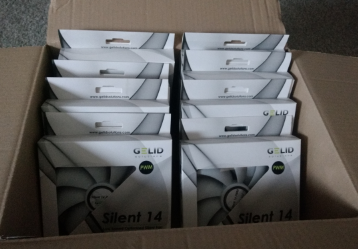
I just received a load of fans to equip the rest of the radiators :chart_with_upwards_trend:
- You can comment out the line
-
Hi,
very interesting project. How did you choose the fan? Did you calculate the CFM or something else (f.i. why Silent 14 and not 12)? How do you assemble the fans, will you replicate any of the commercial solutions?
Thank you.@mortommy No real answer here apart from (my) common sense. Large fans are more silent. These were avaliable for a few €. The size is also dependent on the size of the radiator. As my circuit makes it possible to set the fan speed I can avoid resonance noise.
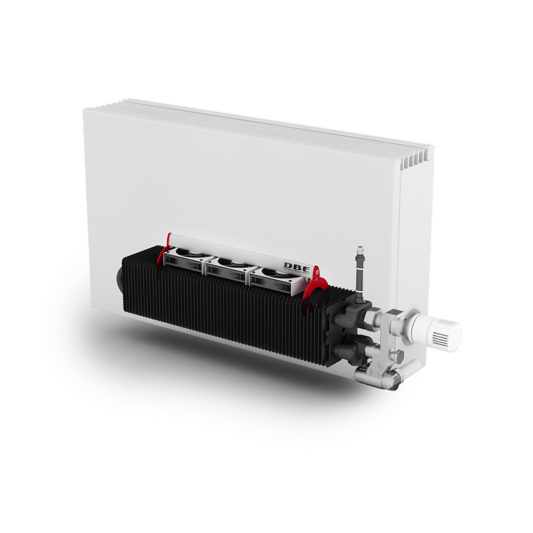
I can place the fans 'in' most of my radiators of the "Jaga"type below:
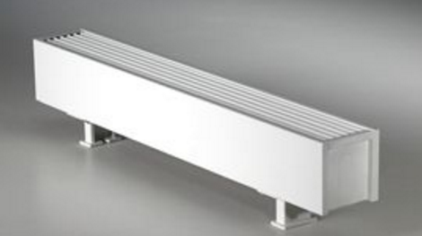
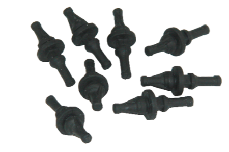
For other types like below I need to make a construction to attach them at the bottow (possibly wood with rubber dampers)
Dampers:
-
@Andrej_AB I think this sketch is doing the job. There are some things to take into account:
- You can comment out the line
#define SPEED_CONTROL_PIN A0 // connect to potentiometer for speed controlif you don't want to have manual speed control. - If you use a PMW fan (4 wire) you need to adjust the PWM frequency to something near 25kHz. ~32 kHz works for me (see sketch) but some fan's are more sensitive.
- You can control a non-PWM fan (2 or 3 three wire) with an external MOSFET. In this case you need to lower the PWM frequency to keep a brushless motor in control. ~31 Hz (see sketch) worked for me with the circuit below (sorry for the quality of the drawing ;-). MOSFET is IRLZ44 or almost any other.

- Be aware that I changed the transmission channel / set a fixed node/ set a fixed parent for my own network
/*
 PROJECT: MySensors / Ventilator control
 PROGRAMMER: AWI
 DATE: february 2, 2017/ last update: february 5, 2017
 FILE: AWI_Radiator_Booster.ino
 LICENSE: Public domain

 Hardware: MySensors 2.0, MOSFET dimmer, Dallas temperature

 Special:

 SUMMARY:

	Full independent with manual mode
	Controls ventilator speed with PWM
	Measure temperature and change speed accordingly

 Remarks:
	Fixed node-id

 Change log:
 20170202 - Created from Ventilator control
 20170205 - Clean code and change manual mode
*/

// Enable debug prints to serial monitor
#define MY_DEBUG
#define MY_PARENT_NODE_ID 0
#define MY_NODE_ID 91											// fixed node number
#define NODE_TXT "Radiator Boost 91"							// Text to add to sensor name
#define MY_BAUD_RATE 19200
// Enable and select radio type attached
#define MY_RADIO_NRF24
#define MY_RF24_CHANNEL 83										// 83, radio channel, default = 76

#undef MY_REGISTRATION_FEATURE									// sketch moves on if no registration

#include <SPI.h>
#include <MySensors.h>
#include <OneWire.h>
#include <DallasTemperature.h>

#define ONE_WIRE_BUS 4 											// Pin where dallas sensor is connected
#define MAX_ATTACHED_DS18B20 3
#define TEMPERATURE_PRECISION TEMP_12_BIT
#define IN_THERM 0 												// indexes of in thermometer, adapt to you situation
#define OUT_THERM 2
#define ENV_THERM 1

#define VENT_PIN1 3      										// Arduino PWM pin attached to MOSFET Gate pin -or- vent PWM pin (adjust PWM-Frequency)
#define VENT_MIN_LEVEL 20										// lowest pwm level for vent
#define VENT_MAX_LEVEL 255										// highest pwm level for vent

// #define SPEED_CONTROL_PIN A0									// connect to potentiometer for speed control, if commented out no speed control

#define IN_TEMP_CHILD	0										// measure incoming water temp
#define OUT_TEMP_CHILD	1										// measure outgoing water temp
#define ENV_TEMP_CHILD	3										// environment
#define VENT_CHILD	2											// ventilator

// Helper for Debug:  1 = Serial debug output ; 2 = V_TEXT remote output ; else no debug
// Use Formats described in fprint() : http://www.cplusplus.com/reference/cstdio/printf/
// Example: 	Printf("Temp %2d Hum %2d\n", temperature, humidity);
// warning: max print size < 24 ; float = NOT supported in Arduino, you need to convert it yourself, ie. dtostrf(Temperature, 5, 2, tempBuf)
#define _DEBUG 1												// 0 = no output ; 1 = Serial debug output ; 2 = V_TEXT remote output
#if _DEBUG == 1													// Serial output
	char printBuf[24] ;											// need temporary buffer
	#define Printf(...) { sprintf(printBuf, __VA_ARGS__) ; Serial.print(printBuf);}	// macro to substitute Printf()
#elif _DEBUG == 2												// if remote debug you need to define a child and present it to the controller
	#define DEBUG_CHILD_ID 10									// Child id of V_TEXT
	MyMessage debugMsg(DEBUG_CHILD_ID, V_TEXT);					// get the debug message ready
	char printBuf[24] ;											// need temporary buffer
	#define Printf(...) { sprintf(printBuf, __VA_ARGS__) ; send(debugMsg.set(printBuf)); }	// macro to substitute Printf()
#else															// No debug wanted
	#define Printf(...)
#endif

const unsigned long heartbeatInterval = 1 * 3600UL * 1000UL ;	// heartbeat, let the controller know its alive
unsigned long heartbeatCounter = 0 ;

const unsigned long updateInterval = 10 * 1000UL ;				// controller update
unsigned long lastUpdate = 0 ;

const unsigned long manualTime = 60 * 60 * 1000UL ;				// manual timer exit to automatic if not reset by controller command reception
unsigned long manualTimer = 0 ;
boolean manualFlag = false ;									// flag for boost machine to indicate manual operation
boolean manualStatus = false ;									// actual status of automatic/ manual

const unsigned long boostTime = 30 * 60 * 1000UL ;				// boost timer: period boost is active
unsigned long boostTimer = 0 ;
boolean boostStatus = false ;
const uint8_t boostTemperature = 30 ;							// temperature on which boost becomes active in Celcius
const uint8_t boostThreshold = 2 ;								// threshold for temperature in Celcius

const uint8_t maxVentLevel = 0xFF ;								// level in max boost
const uint8_t minVentLevel = 20 ;								// level in min boost
const uint8_t runVentLevel = 50 ;								// level in running state (rest)

const unsigned long dimLevelInterval = 10UL ;					// dimlevelinterval
unsigned long lastDimLevelUpdate = 0 ;

uint8_t lastDimLevel = 0x0 , newDimLevel = 0x0	;				// Current or last dim level...

// flags to indicate if transmission is needed, heartbeat and/or changes > treshold
boolean txTemperature = true ;									// flags to indicate if transmit is needed (time / change driven)
const float tempThreshold = 0.01 ; 								// send only if change > treshold (Celcius)

// arrays to hold device addresses and last temp
DeviceAddress dThermometer[MAX_ATTACHED_DS18B20];				// hold addresses
float lastTemperature[MAX_ATTACHED_DS18B20];

OneWire oneWire(ONE_WIRE_BUS); 									// Setup a oneWire instance to communicate with any OneWire devices (not just Maxim/Dallas temperature ICs)
DallasTemperature sensors(&oneWire); 							// Pass the oneWire reference to Dallas Temperature.

MyMessage dimmerMsg(0, V_PERCENTAGE);
MyMessage lightMsg(0, V_LIGHT);
MyMessage temperatureMsg(0, V_TEMP);							// Temp

/***
 * Dimmable LED initialization method
 */
void setup(){
	// Set PWM for vents, PWM 4 wire vents needs 25kHz, PWM 3 wire (voltage controlled) need low frequency PWM < 100 Hz
	// comment out frequency here. (https://arduino-info.wikispaces.com/Arduino-PWM-Frequency)
	pinMode( VENT_PIN1, OUTPUT) ;
	TCCR2B = TCCR2B & B11111000 | B00000001;    				// set timer 2 divisor to     1 for PWM frequency of 31372.55 Hz
	//TCCR2B = TCCR2B & B11111000 | B00000110;    				// pin3, set timer 2 divisor to   256 for PWM frequency of   122.55 Hz
	//TCCR2B = TCCR2B & B11111000 | B00000111;    				// set timer 2 divisor to  1024 for PWM frequency of    30.64 Hz


	// Startup up the OneWire library
	sensors.begin();
	sensors.setResolution(TEMPERATURE_PRECISION);
	for (int i = 0; i < MAX_ATTACHED_DS18B20; i++ ){
		if (!sensors.getAddress(dThermometer[i], i)){
			Printf("no address for Device \n") ;
		}
	}
	// requestTemperatures() will not block current thread
	sensors.setWaitForConversion(false);
}

void presentation() {
	// Send the sketch version information to the gateway and Controller
	sendSketchInfo("AWI " NODE_TXT, "1.0");

	present(VENT_CHILD, S_DIMMER, "Speed " NODE_TXT);

	present(IN_TEMP_CHILD, S_TEMP, "T in " NODE_TXT);
	present(OUT_TEMP_CHILD, S_TEMP, "T out " NODE_TXT);
	present(ENV_TEMP_CHILD, S_TEMP, "T env " NODE_TXT);
}

/***
 *  Dimmable LED main processing loop
 */
void loop(){
	unsigned long now = millis();
	if ( now > heartbeatCounter + heartbeatInterval) {				// alive signal to controller
	    sendHeartbeat();
		heartbeatCounter = now ;
	}
	if ( now > lastUpdate + updateInterval) {						// update all sensors
	    readTempHum();
		lastUpdate = now ;
		boostMachine() ;
	}
	fadeToLevel();													// dimmer fade update
}

void receive(const MyMessage &message) {
	if (message.type == V_STATUS){
		manualStatus = (message.getInt() != 0)?true:false ;
		manualFlag = true ;											// override automatic operation
	} else if (message.type == V_DIMMER){
    //  Retrieve the power or dim level from the incoming request message
		newDimLevel = map(message.getLong(), 0, 100, 0, 255);
		lastDimLevel = newDimLevel ;
		manualStatus = true ;
		manualFlag = true ;											// override automatic operation
		Printf("Level %3d from %3d\n", newDimLevel, lastDimLevel);
	}
}

/* 	Boost state machine
	States:
	- Idle:  	nothing waiting armed, vent off
	- Armed:	active waiting for start
	- Boost:  	starting fast start-up curve,
	- Running:	in action, slow vent
	- Manual: 	commands received from controller, exit after manual timer
*/
void boostMachine() {
	unsigned long now = millis(); 									// loop timer reference
	enum state_t { idle_s, armed_s, boost_s, running_s, manual_s } ;
	static state_t State = idle_s ; 								// start in idle
	if (manualFlag){												// check if manual here is not the best solution, but works
		State = manual_s ; 											// manualflag needs to be reset within time frame
		manualTimer = now ;
		manualFlag = false ;
	}
	switch (State) {
		case idle_s:
			if(( boostTemperature - lastTemperature[0] ) > boostThreshold ){	// arm when in_temp below boost temperature
				State = armed_s ;
				newDimLevel = 0 ;
				Printf("Armed started\n") ;
			}
			break ;
		case armed_s:												// default state, browse through patterns
			if (( lastTemperature[0] - boostTemperature) > boostThreshold){		// when temp rises above threshold start boost curve
				State = boost_s ;
				boostTimer = now ;									// boost lasts for boost time from now
				Printf("Boost started\n") ;
			}
			break ;
		case boost_s:												// boost state with vent curve, wait for completion
			if ( now > boostTimer + boostTime) {					// check if boost time expired
				newDimLevel = runVentLevel ;						// set vent to running (rest) level
				Printf("Boost ended on time, to running\n") ;
				State = running_s ;
			} else {												// boost curve (can be extended now triangle)
				int boostProgress = map((now - boostTimer)/1000, 0, boostTime/ 1000, 0, 0xFF ) ; // progress in 0xFF steps
				const uint8_t maxSpeed = 0x20 ;						//  split point in boost period
				if (boostProgress < maxSpeed){						// speed increase to max for first period
					newDimLevel = map(boostProgress, 0, maxSpeed, 0, 0xFF) ;
				} else {											// slow speed decrease to min for second period
					newDimLevel = 0xFF - map(boostProgress, maxSpeed, 0xFF, 0, 0xFF) ;
				}
				Printf("Prg %d, Spd %d\n", boostProgress, newDimLevel) ;
			}
			break ;
		case running_s:												// steady running waiting for end condition
			if (( boostTemperature - lastTemperature[IN_THERM] ) > boostThreshold ){
				State = idle_s ;
				Printf("Idle\n") ;
				newDimLevel = 0 ;
			}
			break ;
		case manual_s:												// reacting on actions from controller. Exit on timer (or controller command)
			if ( (now > manualTimer + manualTime) || !manualStatus ){
				State = idle_s ;
				Printf("Idle\n") ;
				manualStatus = false ;
				newDimLevel = 0 ;
			}
			break ;

		default :
			State = idle_s ;
			break ;
	}
}

void readTempHum(void){
	sensors.requestTemperatures();					// Fetch temperatures from Dallas sensors
	// query conversion time and sleep until conversion completed
	int16_t conversionTime = sensors.millisToWaitForConversion(sensors.getResolution());
	//Printf("Conversion time %4d ms \n", conversionTime);
	wait(conversionTime);

	// Read temperatures and send them to controller if no error and change > threshold
	float temperature ;
	for (int i = 0; i < MAX_ATTACHED_DS18B20; i++ ){
		temperature	= sensors.getTempC(dThermometer[i]) ;
		Printf("Temp %2d %2dC \n", i, (int)temperature) ;
		if ( abs(temperature - lastTemperature[i]) >= tempThreshold && temperature != -127.00 && temperature != 85.00){
			lastTemperature[i] = temperature ;
			txTemperature = true ;
		}
	}
	if (txTemperature){
		send(temperatureMsg.setSensor(IN_TEMP_CHILD).set(lastTemperature[IN_THERM], 2));		// Send in deg C
		send(temperatureMsg.setSensor(OUT_TEMP_CHILD).set(lastTemperature[OUT_THERM], 2));		// Send in deg C
		send(temperatureMsg.setSensor(ENV_TEMP_CHILD).set(lastTemperature[ENV_THERM], 2));		// Send in deg C
		txTemperature = false ;
	}
}

/***
 *  gracefull fade to global newDimLevel
 */
void fadeToLevel() {
  	unsigned long now = millis() ;
	static uint8_t curDimLevel = 0 ;
	static uint8_t lastAnalogLevel = 0 ;
	if (now > lastDimLevelUpdate + dimLevelInterval){					// check if time for update
		if ( newDimLevel > curDimLevel) {
			curDimLevel++ ;
		} else if ( newDimLevel < curDimLevel){
			curDimLevel-- ;
		}
		#ifdef SPEED_CONTROL_PIN										// if speedcontrol connected
			uint8_t speedSetting = ((long)curDimLevel * analogRead(SPEED_CONTROL_PIN))/ 1024 ;		// adjust level with speed setting
		#else
			int speedSetting = curDimLevel ;							// no adjustment
		#endif
		uint8_t setAnalogLevel = (speedSetting == 0)?0:map((int)(speedSetting), 0, 255, VENT_MIN_LEVEL, VENT_MAX_LEVEL) ;	// calculate new analog
		if (setAnalogLevel != lastAnalogLevel){							// avoid writes to PWM (needed ?)
			Printf("Speed setting: %d\n", speedSetting);
			Printf("Analog: %d \n", setAnalogLevel) ;
			analogWrite( VENT_PIN1, setAnalogLevel);
			lastAnalogLevel = setAnalogLevel ;
			}
		lastDimLevelUpdate = now ;
	}
}
I just received a load of fans to equip the rest of the radiators :chart_with_upwards_trend:

- You can comment out the line
-
Winter is cold and energy consumption going up. Time to get out of my cave and start a new project ;-).
Low temperature heating systems use special radiators which can be benficial also for other heating systems.
With a few PC vents I built a radiator booster to increase yield of my existing radiators. Still in research stage but results are promising. There are a few commercial options but these are either sub-optimal, expensive and not MySensorized:-1:


The workbench example built around a compact MySensors node jModule three Dallas temp sensors and PWM circuitry. The whole thing lives in or under the radiator.


Working principle:
- Measure temperatures for water in/ out and environment.
- Vents start spinning slowly as the "In" temperature reaches a threshold (30 Celcius for now)
- Vent spinning increase in time for a few minutes and then slowly spin down until constant level.
- Vents stop spinning when temperature falls below threshold.
- etc.
Extra options:
- Manual mode, started automatically when (MySensors) controller takes over.
- Fan speed control for tuning
I am curious if anybody has some hands-on experience on how to best tune the system. And will publish details (sketch) if anyone is interested.


