💬 MyMultisensors
-
@Nca78
My best wishes for the new year :)I designed this little pir sensor board last month with an optional lux sensor which i think is a nice sensor associated with a PIR. I will post files soon (I'm recovering today, phew!)
https://www.openhardware.io/view/292/Motion-And-Lux-Shield-V1
I also derivated it with MYSX connector, so it could be plugged on some new neat sensebender mk for instance :)And i've asked a pcba for this sensor board, for curiosity. but i've been busy during december.. let's see what we'll get ;)
But about MyMultisensors. I've designed V2 last month. I didn't need it..just because i wanted to try.
I've improved cost, changed PIR strategy, new mcu, still low power, and size is 30.5x25.5 ! with all sensors, and a new thing too. I stop talking.I should get the pcb soon and i'll show. .
Also, that will be a time2time work on the software part because of the mcu choice. -
Any news about the enclosure ? Or did i miss a comment
-
Hello, this is really an excellent sensor!
I would like to buy the components for this project, but I do not know which to choose precisely: when I am looking for a capacitor 100n pack 0603 I have 16 V, 20 V, 15%, 20% etc ...
Do you have a list of references to help us?
Thanks ! -
I'll put stl for box soon, i need to check few things, and i'm busy.
As i've no time for the moment to upload a complete list with manufacturer parts etc.. it's a 3.3v board without regulator, so with passive >6V (for the 100uF for instance) you should be fine. So for others, 16v etc is enough. Rule i use in general, is 2x what my boards need ;)
-
Thanks, and is it OK if I buy 16V for the passive too ?
Like this one http://www.conrad.fr/ce/fr/product/457889/Condensateur-cramique-CMS-0603-Kemet-C0603C104K4RAC-01-F-16-V-10-X7R-1-pcs?ref=searchDetail for the 100nF for instance. -
Yes it's OK to buy 16V. And it should be a rule to buy x7r, so you should be good with those.
But for big values capacitors (used as power reserve), try to take as low voltage as possible on your circuit as leakage is proportionnal to rated voltage. -
Thank you so much, so I will buy 16V for 1u capacitor or more, and 6.3V for others.
And is there a rule for active ? (Watts, volts, amps...)@particle said:
Thank you so much, so I will buy 16V for 1u capacitor or more, and 6.3V for others.
No, it's the opposite :D
The higher the voltage rating, the more leakage/losses you will have. It's not important for small capacitors, but for reserve capacitors like 100µF it's better to take as low as possible, basically 2x the voltage used on your board.
Honestly it's not a big issue if you use 16V instead of 6V, but with a board as optimized for battery life as this one, it would be sad not to optimize the capacitors also ;) -
Hey!
Sorry for being so late, too much pending projects :)
but here is how looks the custom box for my project. I need to polish a few things, especially sort of mounting plate, then i'll release my stl.
Box is 62x29x 11.6mm
No nails no screws.
i don't like to search my screwdriver or needing screws, or a shorting circuit screw.. So when i can i prefer snaps!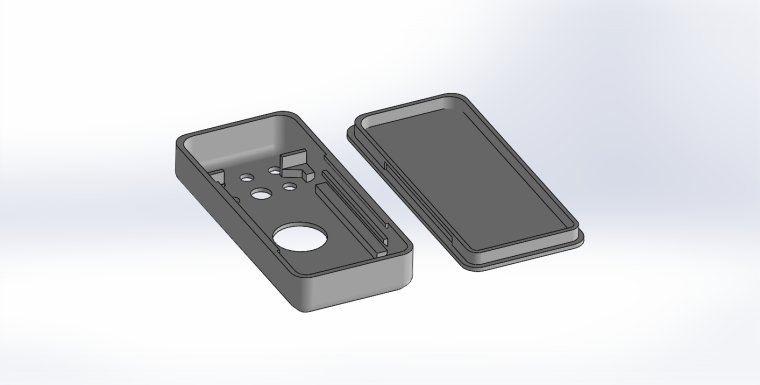
And in real
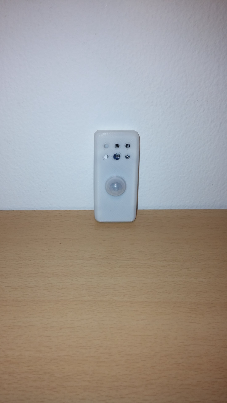
See you soon!
-
Hey!
Sorry for being so late, too much pending projects :)
but here is how looks the custom box for my project. I need to polish a few things, especially sort of mounting plate, then i'll release my stl.
Box is 62x29x 11.6mm
No nails no screws.
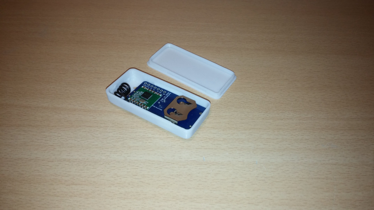
i don't like to search my screwdriver or needing screws, or a shorting circuit screw.. So when i can i prefer snaps!And in real
See you soon!
@scalz Very good work dude ! What about de V2 ? because i want to build this awesome node but i have read somewhere, you are working on the V2 ;)
-
oki.
v2 won't be released soon (not this month sure) because i miss time, also it's not mysensors compatible yet. and not rfm69 too ;)@scalz Oki. And for the nrf24 version ? :)
-
Unfortunately this circuit and pcb contain a little mistake in reverse polarity protection module. Q1 must be connected as on the following diagram

So just reverse connections of drain and source of Q1, and the next version of your board will contain correct reverse polarity protection :wink:
PS
Otherwise your circuit will be powered through mosfet body diode (with a drop to ~0.6V of course) when polarity is crossed. :anguished: -
@Koresh thx for feedback :+1: Files are now updated and added a note
@tonnerre33 sorry for late reply. yes this will be nrf24 compatible, not rfm69. i'll try to show something soon, time does not help me!
-
@Koresh thx for feedback :+1: Files are now updated and added a note
@tonnerre33 sorry for late reply. yes this will be nrf24 compatible, not rfm69. i'll try to show something soon, time does not help me!
@scalz nrf24 for the V1 or V2? Because if V2 isn't mysensors compatible, i prefer use V1 but in nrf24 version ;)
-
So there is no option yet to order complete boards with components in place from manufacturarer? Or am i not getting openhardware correct. Order 10 PCBs will just get me the pcb right?
@Yeitso you are right, 10pcbs order will just give you the pcb ;)
-
I'm finalizing the nrf24 version because it's a nice board, that would be too bad for nrf24 user
Did you finish the nrf24 version @scalz ?
-
@tonnerre33 sorry for delay. yep, sure i finished it a while (rev 1.1 nrf), never ordered it, i use rfm for this node. but i'll upload this week oki
Hello! It looks like you're interested in this conversation, but you don't have an account yet.
Getting fed up of having to scroll through the same posts each visit? When you register for an account, you'll always come back to exactly where you were before, and choose to be notified of new replies (either via email, or push notification). You'll also be able to save bookmarks and upvote posts to show your appreciation to other community members.
With your input, this post could be even better 💗
Register Login