💬 jModule
-
@Qu3Uk I can confirm (from measuring a sample) that the large pad is not connected to anything.
However it is hard to beat the price of an AMS1117 and the AMS1117 SOT-223 package also has smaller thermal resistance compared to the LE33ACZ TO-92 package (all for what its worth )
-
@AWI Wow they are cheap - Perhaps we should get them added to the MYS Store - I need to use up the ones I've got before shipping more stuff half way around the world
-
@aproxx said:
Any chance you will be creating a 'panelized' version of this board? With these small sizes 4 boards can be fitted on a 5 by 5cm board, while still keeping the same price. I'd be happy to order a few if that's available!
I'm just order it, on Dirtyboard not tested yet. Maybe this what you need?
http://dirtypcbs.com/view.php?share=18851&accesskey=01fcfdedf25cb9105e13f2d50d9ea385
-
Nice one!
I really would like to see the version of it for nrf24l01+ SMD
-
Very nice. The only downside I can think of is that AMS1117 is power hungry. Is there a pin compatible regulator with uA level standby current?
-
@ted
I do not care about the power. I use USB wall charger to power my nodes. I can recommend this model (it is almost the size of jModule after removing the case):
http://www.aliexpress.com/item/1pc-High-Quality-5V-1A-EU-Plug-AC-Travel-USB-Wall-Charger-for-iPod-for-iPhone/32581266560.html?spm=2114.30010308.3.299.EEQVE8&ws_ab_test=searchweb201556_6,searchweb201602_5_10017_10005_10006_10034_10021_507_10022_9026_10020_10018_10019,searchweb201603_2&btsid=7f600ac6-6e52-41b9-9da5-5c4379d7a639
-
I modified the design to use a XC6206 serial LDO (1uA standby current). I placed an order with dirtypcb. You can find the design here: http://dirtypcbs.com/view.php?share=19651&accesskey=2e5e31a83bf6fe21510c3bc438e12df7
Will update when I get the board on hand.
-
@julisses Would you mind posting a photo of what that supply looks like inside? Preferably to this thread: http://forum.mysensors.org/topic/2477/are-chinese-power-supply-chargers-that-dangerous-to-use
-
@m26872
Unsolder USB connector and instead of the connector use wires to connect the jModule.
-
@julisses - Be carefull...
More info here: http://forum.mysensors.org/topic/1607/safe-in-wall-ac-to-dc-transformers/ and as @m26872 said: http://forum.mysensors.org/topic/2477/are-chinese-power-supply-chargers-that-dangerous-to-use
I have a couple of those cheap power supplies running some nodes and they tend to give up after some time as well...
If you look after them thats fine... but im not to comfident with those cheap usb power supplies any more.
Just a tip - as I said, have some working fine but be careful.
-
Do you have a link for the angular pin-header? I noticed after soldering everything and could not get the arduino/jModule together that the angular pinheaders have the plastic in the other way. I tried with a new and just turned the pinheaders in the other way, but then the exposed pins got too short, same result when prying of every pin and turning them around manually.
-
I had the same problem, I straightened out a set of angular headers, then soldered them into the board, and bend them at the place I needed.
Not the best solution, but I had to many standard angular pins to go and buy more.
-
-
Nice work!
Is there some kind of female plug that could be used instead? It's nicely compact--except for the male pins sticking out.
-
Regardless, I just now ordered some. Thanks!
-
OK, I "get it" now. The male pins that are sticking out are entirely optional.
-
Did anyone do any power consumption tests on these? I cannot get it below 1.5mA. I think I need to mod my Pro Mini and remove the LED and the regulator.
-
@alexsh1
The regulator on the board (AMS1117) consumes several mA at idle. You may need to find an alternative that has uA level quiescent current. I modified the board to use a XC6206 serial LDO (1uA standby current, see my previous post). I have the board manufactured by dirtypcb and have made sensors. Will test the battery life soon.
-
@ted thanks for your prompt reply. I do not have AMS1117 as I'm running Arduino Pro Mini 3.3V. I figured out it was the Mini itself. I had to remove the onboard regulator and the LED and right now my consumption is 6uA.
I'm moving away from 5V boards as I think these will be phased out eventually.Good point on AMS1117 - this is not a battery friendly regulator
-
@ted said:
I modified the design to use a XC6206 serial LDO (1uA standby current). I placed an order with dirtypcb. You can find the design here: http://dirtypcbs.com/view.php?share=19651&accesskey=2e5e31a83bf6fe21510c3bc438e12df7
Will update when I get the board on hand.
Hello @ted, thank you for the link on dirtyPCB, I just ordered some boards. Do you have any feedback related to battery life when running at 5V ?
-
@AWI said:
@Qu3Uk I can confirm (from measuring a sample) that the large pad is not connected to anything.
However it is hard to beat the price of an AMS1117
Thank you very much for the link, I was about to buy less units for a higher price for another board, then I remembered about seeing a link with very cheap price on this thread
-
Doh .. I just blindly orded this board but after checking the eagle layout .. could it be that your power wiring is messed up? The AMS1117 is chained behind the ProMini LDO which I guess is very weak. Would it be much better to put the raw-input on the jModule, power the NRF24 with the AMS1117 output and the pro mini?
-
Are the boards uploaded to DirtyPCBs good and tested? I'd very much like to order a bunch of these but I am confused by the comments about missing pads. :? Can someone please confirm?
-
@zilog said:
Are the boards uploaded to DirtyPCBs good and tested? I'd very much like to order a bunch of these but I am confused by the comments about missing pads. :? Can someone please confirm?
What missing pads are your talking about ?
I used the panelized version modified by @ted to use XC6206 regulator and it's running fine (though without regulator at the moment as I have not received them yet, I use CR2032). And if you use a 0.6mm PCB thickness it's really easy to cut with regular cissors.
http://dirtypcbs.com/view.php?share=19651&accesskey=2e5e31a83bf6fe21510c3bc438e12df7
-
@ted Hello! Can you share the Eagle file of your version of pcb? I mean this one: http://dirtypcbs.com/view.php?share=19651&accesskey=2e5e31a83bf6fe21510c3bc438e12df7
-
How about a version with the SDA & SCL pins also routed to the header?
Sensors like the Si7021 are using the I2C interface
-
@kted said:
How about a version with the SDA & SCL pins also routed to the header?
Sensors like the Si7021 are using the I2C interfaceI agree with you and I'm going to make a slightly different version of the board, to have both those pins available and to keep antenna away from the pro mini board.
-
Any news on the new board? I am really interested.
-
@EddyG said:
Any news on the new board? I am really interested.
I'm testing a first version right now
It's running fine but there are some annoying defaults.
I'm making improvements to the PCB now and I will publish on openhardware.io in the coming weeks.I'm using SMD NRF 24 with antenna outside for better reception. Radio capacitor is SMD also but big size (1206) so easy to solder.
This is what the assembled board will look like, it takes a bit more surface than jModule but as you can see it's really flat, around 7mm and less than 6mm if you remove the big reset button on the pro mini.
-
Nice, good job. Looking forward too it.
-
Are these new boards compatible to the old footprint? I think the layout of the "high power"-rf24 versions did not change in the past coulpe of years and I can't rely on the "small"-boards .. got a solid home with conrete falls
-
@cimba007 the footprint is different.
I think I have finished the new version now, I changed the regulator from RAW to VCC to put an AMS1117 so you will be able to use high power version of the NRF24 if you want. They exist in SMD version (so, with the same footprint than I use on this board) and they are of better quality than the cheap "through hole" versions, in addition to beeing much more compact with their ceramic antennas.
From my experience even the non pa/lna nrf24 has better radio performance than the cheap through hole version. With addition of not having any connectors/part of board below the antenna (like on the jModule) maybe it could be enough for some of your sensors at home.I have 30cm thick concrete walls in my appartments and no problem with the signal on the sensors using SMD version, while it was not so stable when using the through hole version. Probably my appartment is smaller than your home and I think the signal just "turns around" walls here, but you should give it a try
-
I currently have 5 modules of the "old"-jboard and still 2-3 spare "high"-power modules left. I just recently noticed that most of my communication problems apparently came from RF24_PA_MAX settings. Currently running with RF24_PA_MIN I am very satisfied with the "high"-power modules. Was just inrested int he latest developement.
My recent focus switched over to make some nice housings for my nodes. Having a board+sensors is only half of the work
-
@cimba007 if you are not using amp on the modules then the SMD version will give you better results I'm sure.
If you want to use nice housings you should appreciate the little extras that will come together with the board
-
What about the NRF decoupling capacitor? Is there a provision for it?
In the previous version there were holes for one. Is it SMD now?
Any other details on the new features? My fingers are itching for an order....
-
Yes I switched to SMD because the purpose of the board is to be very compact. With SMD everything is on one side and the board can be on the pro mini bottom without any gap.
But the board stays easy to solder too as I have put a 1206 SMD size. If you can solder the SMD nrf24 you can solder a 1206 capacitor. If you can't, keep using the jmodule, but really it's not very difficultI'll detail the board in another thread, I think I've hijacked this one enough
I'm making additional sensor boards in a hurry to send to dirty PCB and get them before lunar new year. When everything is sent I will upload to GitHub and post on openhardware.io. But it will need a few more weeks for me to receive and test the boards before before I advise you to order.
-
@Nca78 So, the capacitor is on the other side of the board, it just doesn't show in the photos. No problem with the SMD components, they are large enough if you are a bit careful.
You are wasting precious time writing in the forums. Get back to work!
-
Hey I have followed https://www.mysensors.org/build/battery and removed the onboard LED and 3.3 VDC regulator. I have powered using VCC pin. Do I need to external power the nrf module ?
-
@SubodhChettri Since you have removed the regulator, you should power the mini with 3.3V.
This is provided either by the jmodule's LDO which is capable to power the NRF, or directly by the battery (2xAA).
If you are using batteries, you dont need the LDO, so you bridge the Vin& Vout, and the 3.3V that feed the Mini go also to to the NRF.
-
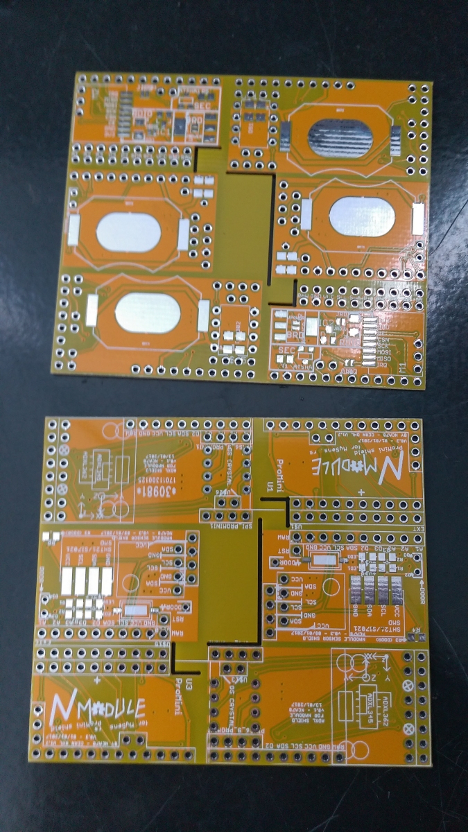
Panels with "NModule" and sensor shields finally arrived
-
@Nca78 is it possible to buy them somewhere?
-
@Cliff-Karlsson said in jModule:
@Nca78 is it possible to buy them somewhere?
I'm not sure it's a good idea to share the dirtypcb link yet:
- they are not tested
- I don't even have all the scripts ready
- they need a bit of documentation to be usable
I will do my best to test them and share on openhardware.io next week.
-
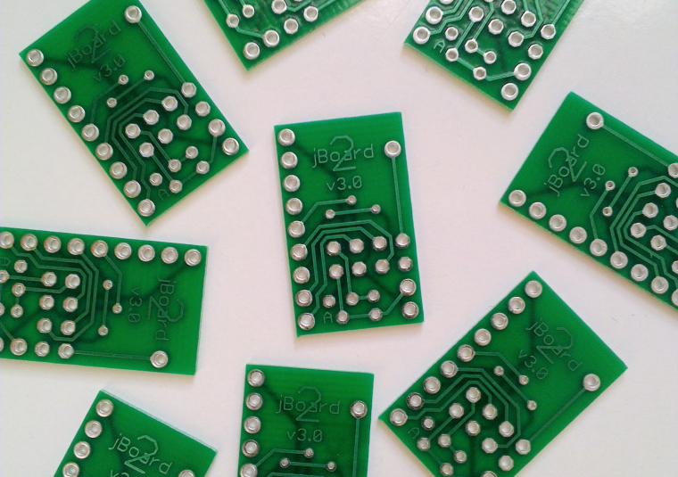
jBoard2 arrived............jModule2 is coming
-
Great, what are the improvements over the v1?
-
@ted Hello! Can you share the Eagle file of your version of pcb? I mean this one: http://dirtypcbs.com/view.php?share=19651&accesskey=2e5e31a83bf6fe21510c3bc438e12df7
Sorry for the extreme late response. I've busy with work in the past half year. Hope you still find the attached file useful.
https://dl.dropboxusercontent.com/u/13998152/modified_jBoard-panalize_4x4_hole.brd
-
@ted Big thanks!
-
@dakipro
The improvements:- 2 build options
- no SMD elements (AMS1117 replaced by LE33 - TO92 package)
- smaller size: the jModule and the jBoard
- output pins in a one row
-
@Nca78 Sorry for the nagging, but are you any closer to releasing it to dirtypcbs or similar?
-
Switching to TO92 elements is a great idea and will make soldering much easier to do. However, LE33 still has 0.5 mA supply current and will not be a good choice for battery powered sensors. The TO92 package will always be ON per spec sheet: http://www.st.com/content/ccc/resource/technical/document/datasheet/98/09/12/54/6e/d1/45/36/CD00000545.pdf/files/CD00000545.pdf/jcr:content/translations/en.CD00000545.pdf
The modification I made previously used XC6206 regulator that only requires 1uA supply current. It works pretty well for my battery powered sensors. However, it does not offer a TO92 package. It will be great if someone can suggest an ultra-low supply current voltage regulator in TO92 package.
-
@ted The lm-2936z could do the job (15 uA Q, 200mV drop-out ) or the mcp-1702 (2 uA Q, 525 mV drop-out). Both are significantly lower priced than the LE33 (at least where I get them )
-
@Cliff-Karlsson said in jModule:
@Nca78 Sorry for the nagging, but are you any closer to releasing it to dirtypcbs or similar?
Yes but had some visitors during 3 weeks so progress was slow, I'll restart in 2 days and post something soon.
It will be great if someone can suggest an ultra-low supply current voltage regulator in TO92 package.
I would suggest MCP 1700 instead of 1702 as suggested by @AWI
It has similar max current (250mA), ultra low quiescent current too (1.6uF) but the drop-out is way lower: below 0.2V which makes it much better for battery use especially if using 2*AA/AAA batteries. The limitation is the maximum input voltage (6V) but on battery it should not be a problem.But be careful MCP 1700 (like 1702) needs two 1uF capacitors at input and output, so it's not a drop-in replacement for LE33.
-
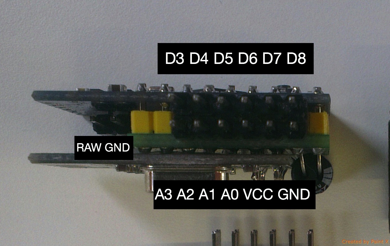
jModule2 is ready
-
@Nca78
Any progress with the n-module?
-
@Cliff-Karlsson said in jModule:
@Nca78
Any progress with the n-module?Sort of Made a temperature/humidity/light sensor and a door sensor.
Both are very similar in size to assembled jModule, but include the sensors and CR2032 batteries. Still have to test the accelerometer child board and make scripts for it and I will put the openhardware.io page online.
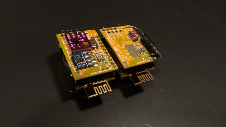
-
Nice!
One question: do you have a mechanism to swap pins on the breakout boards? I know not all manufacturers use the same pinout for their I2C boards. Unfortunately...
-
@DavidZH as you can see on the door sensor I made two connectors for "through hole" I2C that will fit most if not all of the sensors I know: si7021, OPT3001, MAX44009, BMP/BME 180/280, ...
Else you can always solder the matching pins and connect the others using a small wire from breakout board to the right hole in the next connectors row. For SMD si7021 (blue on the picture) I only know of 1 layout.
-
Clear! I will take a deeper look into your board.
-
@Cliff-Karlsson said in jModule:
@Nca78
Any progress with the n-module?It's finally published for the main board, sensor shields will come soon.
https://forum.mysensors.org/topic/6876/nmodule
-
@Dwalt Thank you very much, now I understand better why the measurement of the voltage on input A0 was never good ..