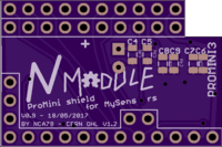
💬 NModule


  • WOW man, this is THE board for mysensors... I've been dreaming about this since I started making nodes 🙂
    And the documentation is equally impressive, one of the best boards and documentations available.

    Just wanted to thank you and ask where donations can be made, you deserve at least a beer for this?

    P.S. I guess I would be pushing it now after all your hard work documenting the board, but hopefully it would be possible to ordered them directly from the website. But it is not difficult to compile necessary files manually.

    Thanks again, keep up the excellent work!


  • Hardware Contributor

    @dakipro Thank you I had been dreaming about it to but unfortunately it didn't exist so I had to make it 😄

    Don't know for any donations, if you really want to please make a donation to MySensors project in my name.

    For the Gerbers you just need to zip the files and upload to website :
    nModule.* files for the single NModule PCB
    NModule_Panel_NModule.* for the panelized version (be careful there are technically 2 designs in that one some websites like PCBWay will refuse and ask you for 20-30$ extra...)


  • Admin

    @Nca78

    Which file types did you have problems uploading?


  • Hardware Contributor

    @hek it refused the .dri and .gpi files.
    dri is Drill Station Info File
    gpi is Photoplotter Info File

    But it seems they are "information" files and not mandatory to make the PCBs so there're enough on openhardware to get the boards produced.


  • Hardware Contributor

    @dakipro said in 💬 NModule:

    P.S. I guess I would be pushing it now after all your hard work documenting the board, but hopefully it would be possible to ordered them directly from the website. But it is not difficult to compile necessary files manually.

    Missed the option on the openhardware website. I just created a revision so you can order directly if you want...


  • Hardware Contributor

    @Nca78
    Looks cool 🙂
    I'm also preparing docs actually, for same sort of project (mainboard and sub boards, proto ok). Mine is a bit different (not 328p) but I also have a board for PIRs (AM312 compatible with sr501fresnel).

    Nice work 👍


  • Hardware Contributor

    @Nca78 - really nice!
    What kind of connector do you use? Did you consider the MysX connector by @Anticimex for your shields ?
    That would be great because then it could be used with other boards as well (EasyPCB for example and alof of other).


  • Hardware Contributor

    @sundberg84 said in 💬 NModule:

    @Nca78 - really nice!
    What kind of connector do you use? Did you consider the MysX connector by @Anticimex for your shields ?
    That would be great because then it could be used with other boards as well (EasyPCB for example and alof of other).

    Thank you 🙂

    I didn't really make a connector, in that case I would have used the MysX connector.
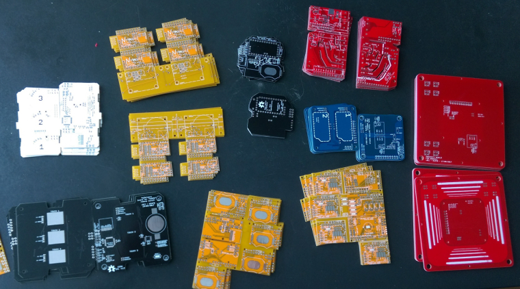
    What I wanted was to have all pins on one side, and when necessary enough pins on one row to manage the sensors on the shield so that the full sensor can be as small as possible. Starting from a ProMini this was very limiting so my "connector" consist of power pins (RAW, GND, VCC), A1-A3 from the other side of the board (and at the moment only used as digital pins on the shields) and A4/A5 to have I2C.

    There's only a small step to adapt the shields to MySX connector so I will do it for the more popular/used shields when I will have cleared my "PCB backlog" 😄 (12 PCBs in production right now...)
    I also want to make sure the current versions run as expected before forking them.


  • Hardware Contributor

    @sundberg84 I see on openhardware.io that there's nothing except your board using MysX connector, so maybe instead of adapting each of my shields I could make a MysX sensor shield specially adapted for EasyPCB ? It would contain sensors easy to solder and to program, I supposed what makes sense with your board: temperature/humidity/light/general I2C, reed switch, connectors for switches, accelerometer, ... You can contact me by private message to discuss it if you want as you know better than me what usage people do of your board.


  • Hardware Contributor

    @Nca78 - thanks for your reply!
    I know anticimex boards should have MysX and the MYS/sensebender gateway as well (without doublechecking).
    Here is a published info about the connector https://www.mysensors.org/hardware/mysx and I personally think its a great idea that if everyone uses this it could be easy to swap mother and daughterboards. Anyways... not always easy to design and fit but just a thought for you in the future.

    Great design and idea with your boards! Keep up the good work! 👍


  • Hero Member

    This looks like an excellent project. In the end i'm not sure which is easier and faster: unsoldering parts from a pro mini or soldering an atmega328p and a few parts onto a pcb. I suppose a pro mini is less expensive though in small volume. For me, since I burn the latest optiboot, the dip chip seems maybe slightly easier to setup.

    Having a bunch of pre_made shields, though, is a definite time saver. This project should, justifiably, appeal to a lot of people.

    Fantastic!


  • Hero Member

    By the way, for those who don't already know, ChipQuik is a great aid in unsoldering parts from a Pro Mini: https://www.amazon.com/ChipQuik-SMD1-Leaded-Temperature-Removal/dp/B0019UZP7I/ref=sr_1_sc_1?ie=UTF8&qid=1495997244&sr=8-1-spell&keywords=chipqwik
    I use it all the time whenever I need to unsolder SMD parts.


  • Hardware Contributor

    @NeverDie thank you !
    I agree about the SMD atmega it's quicker to solder than all the pins on the ProMini, but if you take the full process including the 2 or 3 extra caps, pullup resistor for RST, cleaning the flux, checking you didn't make any shortcuts between those tiny pins etc etc I think it's faster with the ProMini as it's pretty hard to miss a through-hole solder point and removing 2 leds and regulator is less than one minute for me even with bad eyes and short term experience only with SMD.

    About ChipQuik I find it expensive, it seems cheaper to fail on a less-than-2$ ProMini once in a while 😄

    And for max efficiency there's the hot air gun, I have a cheap one (65€ I think, express delivery included) but it's still magic enough to bring the time to only a few seconds per board when you process a bunch at the same time.


  • Hero Member

    @Nca78

    I'll give the hot air gun a try. Thanks for the suggestion!

    I hadn't realized that the PCB for this project is as big as it is until I went to order one from Osh Park just now. They want $18.85 for three. Maybe you can post a version with just the core pro mini shield but with the battery related part and the antenna silkscreen amputated? That would reduce the PCB cost by a lot. I haven't delved into it, so sorry in advance if perhaps the question is overly simplistic. I'm guessing there may be others like me who want to try it and who have alternate ways of powering it.


  • Hardware Contributor

    @NeverDie yes that's how it was not so long ago, that's why it's small like that on the pictures I didn't have the battery/power part nor antenna support.
    I'm more used to Seeed, DirtyPCB, Elecrow and PCBWay so size doesn't matter if you stay below 55cm or 1010cm.

    I added the small part below antenna because with previous version I had a case when I unsoldered the radio module during manipulation. But I get the point it's not worth it if you pay board per surface.
    It's easy to make so I'll add NModule_Core.xxx gerber files ASAP.


  • Hardware Contributor

    I just updated the page with the links to the sensor shields.

    @NeverDie I also uploaded some NModule_Core files (.brd and gerber files) to get PCBs from PCBs.io or OSH Park.
    PCBs.io is US$3.87 and OSH Park US$4.80.


  • Hero Member

    Thanks! I just now ordered it:
    0_1496242365812_nmodule_top.png 0_1496242388235_nmodule_bottom.png
    $4.80 is a lot better than $18.85. 🙂


  • Hardware Contributor

    @NeverDie said in 💬 NModule:

    $4.80 is a lot better than $18.85. 🙂

    But $18.85 was still very cheap for such a great board 😄 😄 😄


  • Hardware Contributor

    Christmas in June ! 😄

    0_1496635055360_IMAG1734.jpg


  • Hardware Contributor

    NModule works with 3.3V power from header/programmer, and with a coin cell on the "power" board attached to it (tested with CR2025 and 220µF electrolytic capacitor).
    I'll continue the tests tomorrow.

    0_1496684111747_IMAG1740.jpg


  • Hero Member

    Not a big deal, but the silkscreen printing is jumbled together, making it hard to read:
    0_1497303419817_nmodule.jpg

    Not sure if you're seeing it on your boards that way or not, but that's how OSH PARK did it.


  • Hero Member

    Also, there are a number of "Pro Mini" type boards on the marketplace, and not all of them are 100% pin compatible. Which did you choose as your model? Is it the Sparkfun Pro Mini (which, if I'm not mistaken, was the first and the root of it all)? You may want to show a photo of the pro mini you're assuming along with a caption reading "your pro mini should look like this" just to avoid confusion.


  • Hardware Contributor

    I think you're the first to ever have a board made by myself in your hands. Congratulations 😄

    For the PCB it's probably due to a mistake from me when modifying the board to make the "core" Gerber version or when exporting files. I will have a look and fix asap.

    For the ProMini I mainly use "The Simple" version from AliExpress, but my local seller has some "Sparkfun" branded clones and they are fine too.

    You should only solder the connectors on the long sides and A4+A5. If it's not clear enough when reading assembly process please tell me.
    Both types of ProMinis have the same layout for side pins and A4/A5, only the programming header and A6/A7 pins are different so it has no importance for NModule.


  • I have used Seeed PCB service a few times in the past. They are not quite the cheapest but still excellent value, and for that little bit extra they do a better job than most.


  • Hardware Contributor

    @Ximper well at US$4.90 for 10 boards up to 10*10cm they are the cheapest now 😉


  • @Nca78 Oh yes, it's $4.9 now. My last order was in March this year, it was $9.9 at at time, thank you for the correction 👍


  • Hero Member

    Wow. $4.90 sounds great. What's their total turnaround time, including delivery? Actual delivery time, not just advertised delivery time, I mean.


  • Hardware Contributor

    @NeverDie they take 5 opening days to make the boards.
    Than the shipping depends on what option you choose, but cheapest shipping is US$11 with HK Post (no tracking), it seems to take around 2 weeks to arrive in the US.


  • for best battery life it is advisable to burn bootloader mentioned in the text.
    How much would a battery lifetime be, for example one single temp sensor reading every 5min?
    When using custom bootloader, then over the air updates cannot be used? Or could the MYSBootloader be configured to take most of the cr2025 battery?


  • Hardware Contributor

    Hello @dakipro,

    what is necessary is to remove the default BOD limit, it is set at 2.7V and that is too high :

    • even if CRxxxx cells were running like alkaline cells, this would waste a big share of the capacity, around 30% I think
    • CRxxxx are not like alkaline cells, they have a high internal resistance and can supply only a limited amount of current, else the voltage drops. Meaning that in fact you will reach this 2.7V much faster if you have several RX/TX in a row

    That is the main limit. I also advise to change the frequency to 1MHz and use internal oscillator if you have no calculation to do: door sensor, all basic I2C sensors etc etc because at 1MHz the power consumption is significantly lower. With NRF24 and I2C sensors it will not slow the "on" time much, data sent to/from radio and sensors takes very little time to transfer and main time is for waiting for radio reply or data from sensor: not affected by frequency so better have consumption as little as possible.

    For battery lifetime if you remove leds and regulators with si7021 it will be way over 1 year. I have not tested those sensors for long enough, but I've had some round "puck" sensors with si7021 running for a few months on chinese CR2032 and I have not seen any voltage drop. Interval time is set to 1mn, it's not sending 5x more than 5mn interval (because often in one minute temp/hum don't change) but probably 2-3 times more, and with that I have no doubt the batteries will last way over a year.

    My entrance door sensors is my oldest sensor, also running on pro mini (and still have it's TX led) and chinese CR2032, it uses the normally opened + normally closed reed swich and after 14-15 months of use is still at 85% of battery.

    You can check that on battery life calculators anyway :

    • with WDT disabled (= when you are not waking up periodically) consumption of board is below 2uA
    • with WDT enabled and si7021 I measured it below 6uA
    • when on with radio enabled for transmit/receive, at 1MHz power consumption is around 15mA when battery is new, a bit lower

    This is a worse case scenario with battery capacity lowered to account for chinese battery (brand name is 220), and long wake up time with radio considered always on, sending data every 5 mns.
    In reality radio is switched on only when data must be sent so time for reading voltage and sensor value is done consuming around 1mA at 1MHz.
    0_1499308138647_wcs.png


  • thanks for detailed explanation, I was always a bit skeptical towards those small batteries, but your module (and documentation) clears all doubts 🙂
    Do you have any experience with OTA updates? I understand that it also needs custom boot-loader (sorry still not having enough understanding about all the things that are involved in making one node, a lot of new terms for me 🙂 )


  • Hardware Contributor

    @dakipro no sorry I'm not (yet) using OTA.
    But yes you need a specific bootloader that will download the new code from the controller and update flash memory of the atmega. There are 2 solutions for this (sorry forgot the names of bootloaders but check the documentation):

    • a bootloader that needs an external flash chip to store the downloaded code. It's a constraint, but it allows the sensor to continue running during download and it will be "offline" only for a short time during memory copy & reboot
    • a bootloader that will copy directly the new code to the flash memory. It means as soon as the sketch started to download your node is offline until all the sketch is downloaded. And if update fails, your old sketch is still gone

    OTA also need some specific code to check for the updates.


  • Thanks 🙂
    Then I guess all that is left is to motivate you to start OTA and improve it (finetune) it to nmodule 🙂
    I used it for regular modules and it is really practical, but I never had much luck with optimizing modules for battery performance. I would get a half year/year with 2 AA batteries, which is not that good comparing with your tweaks for CR battery.

    Keep us updated on other modules, people are waiting for your tests to start ordering 🙂


  • Hardware Contributor

    @dakipro for OTA I don't think there's much to do with batteries & OTA' Either the batteries allow continuous load (CR123, AAA, li-ion etc) or you just can't do it.

    For battery life it's pretty simple but people keep choosing the wrong options and end up with poor battery life/instability etc etc. That's the reason I created the NModule: cheap and sure way to get a good battery life. Then I got a bit wild with the "shields" but that's another story 😄

    For other shields I'm making (slow) progress but I hope to take NModule, TH, Light/SSR, dual touch button, MiLight bridge and PWM boards out of the "work in progress" status during the next 2 weeks.

    0_1499479885941_IMAG1807~2.jpg


  • Hey @Nca78 I received the boards and components (yay!)
    But... I connected three modules, and none of them works 😞
    They all have transport (radio?) fail like

    32 TSM:INIT
    49 TSF:WUR:MS=0
    81 !TSM:INIT:TSP FAIL
    98 TSM:FAIL:CNT=1
    114 TSM:FAIL:PDT

    I tried connecting radios from two different batches, I tried connecting only the radio and arduino, I tried powering it from separate powersupply and only debug via serial. I tried provided sketch and also tried dummy sketch from the examples. I tried using the CR battery, node works fine except that the radio doesn't start communicating.
    I do measure 3V on the radio pins. I tried with and without radio cap.

    I am using chinese silicon mat to solder components on, I read somewhere that you use something similar *(not that I am spying on you 🙂 ) but could it be that I am frying all the radios with static electricity?
    I have used the mat before and it works fine with regular radios, nothing fried so far, but there is something preventing nodes from working 😞

    Do you have any suggestions on how I can debug them and see what seems to be the problem?


  • Hardware Contributor

    Hello, @dakipro, can you show a picture of one of the board ?
    Did you short the jumpers (JPOWER and JRDIO) if you're not using any regulators ?

    Yes I use a cheap silicon mat because it's so convenient, and I never had any problems with it all my radio worked.


  • Hero Member

    @dakipro
    I get the impression that not all radio modules use the same pinouts. You may want to confirm that yours are the same as @Nca78's in that regard.


  • Hardware Contributor

    @NeverDie is right. Some modules like those from CDEByte are different from the classic SMD modules from AliExpress and must be soldered on the "pa/lna" pinout (the one closest to the edge of the board).


  • Hero Member

    Looks as though the PA/LNA part of the silkscreen warning got largely obliterated by the solder pads.


  • Must I have a radio cap?
    I connected the jumpers now quickly for a test (missed the part that I need them), but still same error

    49 TSF:WUR:MS=0
    81 !TSM:INIT:TSP FAIL
    98 TSM:FAIL:CNT=1
    114 TSM:FAIL:PDT
    10158 TSM:FAIL:RE-INIT
    10174 TSM:INIT
    10207 !TSM:INIT:TSP FAIL
    10240 TSM:FAIL:CNT=2
    10256 TSM:FAIL:PDT

    Here is the photo of the board (a bit blurry, I can take it again if it helps)
    0_1506263553498_IMG_0702-800.jpg

    I am missing the radio cap as I was testing lest night without them, but I can solder them in a few hours and test again if you think it will help.

    I connect power to the vcc pin of the "connection pins" right?

    Radio is the one linked in the BOM from aliexpress


  • I put the radio cap back (4.7uf the largest I have in smd), but still same error 😞


  • Hero Member

    @dakipro

    Your photo seems to show some hair-like filaments. Don't know if they're conductive, but, if so, maybe they're bridging some of your solder pads? Have you checked with a continuity meter?


  • checked between the pins, no radio pins are touching each other. Those hairs er most likely from the cat, got them cleaned after the photo.
    I will try to make one more module in a few days and test.

    But to confirm, for the simplest module I need >4.7uF cap, pro mini and the radio, two jumpers (jpower and jrdio) and some mock sketch, and it should all work?
    Have I missed some other jumper or resistor or some other component maybe?


  • Hardware Contributor

    @dakipro no you're not missing anything now.
    Cap is not even necessary at the moment don't worry about it.

    Problem is connection with radio so you have to make sure :

    • VCC and GND pins of radio are correctly connected (seems it's done)
    • SPI pins are correctly connected to the radio, check the "connecting the radio" page for the pinout on the pro mini, and radio module pinout. Then check continuity from radio connector to matching pin on radio side, you might have a soldering problem.

  • Hardware Contributor

    @dakipro you can also check the continuity between adjacents pins of the radio modules, it should be in MOmhs, if lower that could be a reason for failing communication too.


  • Hardware Contributor

    @Nca78 said in 💬 NModule:

    @dakipro you can also check the continuity between adjacents pins of the radio modules, it should be in MOmhs, if lower that could be a reason for failing communication too.

    Just reading on computer instead of phone and I see you did it already, so except a connection problem with the SPI pins I don't see any reason for failure...


  • Hardware Contributor

    @dakipro said in 💬 NModule:

    Thanks 🙂
    Then I guess all that is left is to motivate you to start OTA and improve it (finetune) it to nmodule 🙂

    Just did OTA on a main powered NModule with MYSBootloader and it worked like a charm.
    I will test with a battery (CR123) module at 1MHz now, and post a tutorial later.


  • Hero Member

    @Nca78 said in 💬 NModule:

    post a tutorial

    That would be awesome.


  • IT WORKS!! Life is worth living again...
    I've assembled now fourth module and it works, only different thing I did is that I have soldered the radio and power jumpers before connecting the module together. It could be that without jumpers essential component of all electronics (white smoke) gets out of the radio, not sure what happened. But it works!

    I was struggling a bit to figure out all components needed and all the steps, it might be helpful to have a "short guide", this is for my own reference of what I did in order to get CR2032 module for using with TempHumDoor shield:

    Components needed [nModule]: pro mini, radio, nmodule board, 1 capacitor for radio larger then 4.7uf (I har only 10uf, I have ordered 47uf for future modules).

    Assembling process

    • Burn 1mhz bootloader on pro mini
    • solder two jumpers for jpower and jrdio
    • solder the radio to the board
    • Control that there is no connection between the radio pins, resistance is at least above 200Kohm (don't skip this part thinking it cannot happen to you, it will happen)
    • Solder >4.7uf (f.eks. 10ud) smd.
    • Solder all legs to arduino (except last two RXI and TX0, you will see them missing when you align nModule)
    • Take off the plastic from the legs, before you solder it to the radio (do this BEFORE you solder it to the board)
    • Solder arduino to nModule board
    • Since the capacitor is very small, just check if there is no short between plus and minus (vcc and gnd) pins, as somehow I managed to short them on one module, it turned out that one of the caps was shorting it, probably by overhitting or something.

    Upload mockMySensors sketch and check that node works properly (spare yourself a trouble, no point continuing further if this doesn't work) By this point you should have node looking like (better then) this:

    0_1506632551397_THD nModule 3 - IMG_0730_1024.jpg

    TempHumidityLightDoor shield components: SMD SI7021 for temperature and humidity and a MAX44009 for light, two capacitors larger then 100uf (I used two of 100uf, waiting for 220 to come). And the work so far.

    You basically solder these three/four components and the battery holder as described on the shield here https://www.openhardware.io/view/398/NModule-Temperature-Humidity-Light-Door-sensor-shield
    I didn't yet solder LEDs, but they are accessible after assembling the module.
    Then it looks like this:

    0_1506633186422_THD nModule 4 - IMG_0725_1024.jpg

    0_1506633204869_THD nModule 1 - IMG_0720_1024.jpg

    Now that nModule #1 is completed, you continue with other modules

    0_1506633280285_THD nModule 2 - IMG_0722_1024.jpg


  • It is great to hear that OTA update is coming soon @Nca78 looking forward to the tutorial 🙂


  • If the "power" board is used, shall I keep the voltage regulator on Arduino? Without it, i think powering the board from RAW pin will not work.


  • Hardware Contributor

    @Haozhi-Wang it will depend how you connect things on the "power" board and/or what regulators you use on the NModule board.
    There are 2 reasons to remove the regulator :

    • save energy if you are running on battery, it's not a big waste so if you are using CR123 or AAA you can keep it so it's possible for you to power from RAW with a higher voltage
    • when powering from main, allow higher RAW voltage with a better voltage regulator on the NModule or the "power" board (on promini clones usually the maximum voltage is usually 9V)

    There is a connection between the RAW pin of the promini (on the long side) and the RAW on the "power board", so whether it will work if you use a regulator on the "power" board and remove regulator on the promini will depend on the promini you use, if there is a track betwenn the 2 RAW pins or if it goes through the regulator.

    I hope it answers your question, if not please describe more clearly what sensor you are building, with what power source and why you want to power it from RAW.


  • Guys, pls. have in mind that Ebyte short NON pa+lna module uses pa+lna pinout.
    Took me some time to figure it out


  • Hardware Contributor

    I love those shields... to bad they dont use MysX connector 😉 Any thoughts about 2.0 rev?


  • Hardware Contributor

    @sundberg84 I'm working on it 🙂


  • @Nca78 Thanks you for you detailed answer.
    The power source i am going to use is a CR2032. My bad, I overlooked the three RAW, VCC and GND connectors (yellow) on the power board site.
    For my case, i think shout circuit of JPOWER will be a even better solution


  • Hardware Contributor

    @Haozhi-Wang said in 💬 NModule:

    @Nca78 Thanks you for you detailed answer.
    The power source i am going to use is a CR2032.
    Yes, for that case you need to short JPOWER and JBRD.
    And don't forget to double check your USB adapter every time you connect it to your computer, to make sure you have selected 3.3V, else you will fry your radio with 5V.


  • Hi there!
    I've ordered 10 PCBs from iTEAD, so now... I'm plenty of them to do some tests.
    Can you confirm these Minis are ok?
    https://www.aliexpress.com/item/10pcs-ATMEGA328P-Pro-Mini-328-Mini-ATMEGA328-3-3V-16-MHz-for-Arduino-3-3V-16/32784455996.html?spm=a2g0s.13010208.99999999.271.swhWGM

    Btw, I have some battery boosters, I have used them already with success on breadboard. Have you got any experience about it? Do you think the PCB is hackable to integrate it?

    https://www.aliexpress.com/item/Low-Quiescent-Current-1-5V-1-8V-3V-to-3-3V-Boost-DC-DC-Converter-Board/32802383877.html?spm=a2g0s.9042311.0.0.HOilhS

    Thanks!


  • Hardware Contributor

    @ghiglie said in 💬 NModule:

    Can you confirm these Minis are ok?
    https://www.aliexpress.com/item/10pcs-ATMEGA328P-Pro-Mini-328-Mini-ATMEGA328-3-3V-16-MHz-for-Arduino-3-3V-16/32784455996.html?spm=a2g0s.13010208.99999999.271.swhWGM

    Yes they are ok, they seem to use the Sparkfun layout if I believe the reset button and the position of the A6/A7 pins. I use the boards with a smaller, rectangular reset button on my NModule PCB. The only problem I ever had with "different" ProMini board was the connection between the vcc of the programming header was cut when removing the voltage regulator so board was not powered anymore when using FTDI adapter.

    Btw, I have some battery boosters, I have used them already with success on breadboard. Have you got any experience about it? Do you think the PCB is hackable to integrate it?

    No, if you use a booster you need some extra caps for filtering the output, and a voltage divider to measure battery voltage, there's no space for that on NModule. I made NModule to have a compact "all included" board, so it's made to use low power sensors, that can run at low voltage so you don't need a booster.
    If you really want to use a booster try EasyPCB.


  • Thanks @Nca78 ! I'll order some a lot of 10. Just in case...

    @nca78 said in 💬 NModule:

    EasyPCB

    You'r right. Thanks for this clarification - really don't need to use the boosters or have battery measurements, so I'll keep the sensors small as you designed.


  • Hardware Contributor

    @ghiglie said in 💬 NModule:

    or have battery measurements

    You will have battery measurement, because you will power the atmega with the battery directly so it's possible to read Vcc.
    When you use a booster Vcc is always the same so you need a voltage divider on the battery to know it's voltage.


  • @nca78 said in 💬 NModule:

    @ghiglie said in 💬 NModule:

    or have battery measurements

    You will have battery measurement, because you will power the atmega with the battery directly so it's possible to read Vcc.
    When you use a booster Vcc is always the same so you need a voltage divider on the battery to know it's voltage.

    Sorry, n00b here! 😞 Thanks again, nca!


  • Hardware Contributor

    @ghiglie no use to be sorry, we were all beginners at some point in time 🙂


  • @nca78 Hi, I am trying to use nmodule without batteries and connect 12v as a power source from usb breakout. I am not sure if I should remove the voltage regulator from pro mini? Also, should I add my own regulator to the nmodule (on BRD section)? Where should I connect my + and - from usb breakout to the nmodule? Thanks alot!


  • Hardware Contributor

    Hello,

    what does that mean ?
    @zmatokan said in 💬 NModule:

    connect 12v as a power source from usb breakout.

    Do you power the board from 12V or 5V ?


  • @nca78 said in 💬 NModule:

    Hello,

    what does that mean ?
    @zmatokan said in 💬 NModule:

    connect 12v as a power source from usb breakout.

    Do you power the board from 12V or 5V ?

    Hi,

    thanks for a very quick reply. I am trying to use a 12v external power source to power the arduino + radio + nmodule board. I tried soldering AMS1117 3,3V to the BRD part of the nmodule board, but when I connect my 12v (+ to the RAW pin and - to the ground) I do not get the regulated voltage at the nmodule shield breakout.

    In essence I would like to make my nmodule board work without batteries, by using external power source (usb breakout that is connected to android 12v adapter). This 12v would be regulated by AMS1117 that I solder on BRD part of the board. This way both arduino and radio would get 3,3v and nmodule board would push that voltage to the shield trough vcc and gnd. Maybe I am looking at this the wrong way?

    This the quote on your OpenHardware page that I am using as a guidance:

    "footprint for an AMS1117 regulator (light blue) if your source voltage is too high for Arduino (> 5.5 V or > 3.3V for 8MHz version). AMS1117 can handle up to 15V and 800mA but it consumes a lot of power, so this regulator should be used only for "wired" power (12V, USB, ...) and never with batteries. If you are using only this regulator, the capacitor of the radio should be enough to keep it stable, but if you want to be on the safe side, you can use the capacitor footprints on the other side of the board: C6/C7 for input C8/C9 for output."

    I managed to make my double AAA version to work without problems and kudos for great work!

    Thanks alot!


  • Hero Member

    @zmatokan Luckily NCA78 has a really good track record of picking low priced parts that are nonetheless really good parts. If worse came to worst, that AMS1117's thermal protection would turn the AMS1117 off until it could cool down rather than overheat to the point of destroying itself.


  • Hardware Contributor

    @zmatokan ok it's clear now.
    So yes you should remove the regulator on the pro-mini, because it's also doing voltage regulation from RAW to VCC and it can't work in parallel with the AMS1117.
    Then if you have added ceramic capacitors (one for input, one for output, 1uA each) and connect 12V on RAW and GND you should have 3.3V on VCC. Then you can short JRADIO to send the 3.3V to the radio module.


  • Hardware Contributor

    @neverdie thank you for the kind words, but in this case the AMS1117 was not a "selection", it's just the cheap regulator that is used everywhere 🙂


  • @nca78 Thanks for the info, Il try it today!

    Works like charm! 😄


  • @Nca78 Hi, looks like I am doing something wrong in my last attempts to use your design with 12v external power supply.

    I am using:

    • Arduino 5v, 16hz
    • AMS 1117 5.0V
    • 662K XC6206 - 5v to 3.3v voltage regulator for radio
    • 10UF-16V CAP for radio
    • NRF24L01SMD

    As you can see on a picture, I am using a terminal block where i push 12v.

    IMG_3554.jpg

    When I connect the power to the terminal, my Voltage regulator get veeery hot and nothing works.
    When I connected my FTDI to try to upload a sketch, a capacitor on arduino got fried. You can see it in the next pic.

    IMG_3555.jpg

    This happened on tree of my boards.

    Can you please take a look and try to see where the problem might be?

    Thanks alot!


  • Hardware Contributor

    @zmatokan said in 💬 NModule:

    587488927515_IMG_3554.jpeg](Uploading 100%)

    Hello, I cannot see the picture, I think something went wrong during the upload...
    Can you confirm that you didn't solder the jumpers ? Did you solder the input/output capacitors for each regulator on the other side of the board ?


  • @Nca78 Thanks for the quick reply.

    I hope you will be able to see the images now:

    https://imgur.com/oRBrXDu

    https://imgur.com/2Dexy8Z

    What jumpers are you referring to?


  • Hardware Contributor

    @zmatokan said in 💬 NModule:

    What jumpers are you referring to?

    JPOWER and JRDIO, they should be unsoldered if you are using regulators.
    I see JRDIO is not soldered, I can't see JPOWER as it's below the AMS1117, but I supposed you didn't solder it.

    Components seem ok, can you explain the problem ? Do you have 5V at the output of the AMS117 and 3.3V at the output of the XC6206 ?

    [edit] those "blob" modules are usually of very poor quality, so if you have the right voltages but can't make a radio connection, they might be the reason...


  • @Nca78 I didn't soldier JPOWER either.
    Problem is that when I connect 12v to terminal block, my voltage regulator gets very hot and arduino is just showing red led ad not responding to reset.
    If I try to connect FTDI cable to upload a sketch, I got my CAP on arduino fried as you can see in the image.

    If I try the same thing on simple nmodule (without battery part), it works when I push 12v to RAW and GND.
    Maybe the battery pcb part is making problems? Should I soldier C4...C9 on the back of the nmodule pcb?


  • Hardware Contributor

    @zmatokan sorry I complained about your missing pictures and didn't notice you had explained the problem in your initial message.
    A very hot regulator sounds like a short circuit on it's output. Is the red led on at full level or dimmed ? Can you confirm which regulator is getting very hot ?
    Burnt tantalum capacitor is either voltage higher than rated voltage or reverse polarity. This capacitor is I think connected between RAW and GND, so I don't see how this could happen, did you have 12V on terminal block when you connected the FTDI ?

    For the source of the short circuit (can you check resistance between VCC and GND, and radio VCC and GND ? Not a good idea to do that usually but it will easily confirm the problem here) I have no idea. I don't think it comes from the "power/battery" part of the board, it's pretty basic and it would short RAW not VCC. You could have a problem with radio footprint (but if it's the same module on the non 12V powered board, it's not the reason), or a short between some via on the radio module with the second radio footprint that is below it (red color on picture below)
    alt text

    You should have at least one capacitor for each couple of footprint for input (C6/C7) and output (C8/C9) of the AMS1117. It's not what is causing the problem now, but it will make the power more stable.


  • @Nca78 Thanks a lot for a quick and detailed response.

    I tried last night with the regular nmodule pcb (without battery part) and that one didn't work either (seems like the ones that were working before were connected to 5v power supply, not 12v).

    Arduino led is at full level and radio is not connecting.

    Please confirm that you see this picture:
    Should this pads be connected like this? C7 and C6 are connected, not sure if its the problem with the manufacturing or is it meant to be connected?
    Another question is: should I connect pads in YELLOW or RED direction? (probably stupid question)
    So far I connected them in yellow direction C7->C7
    Could this be connected with the problem?

    Screenshot 2020-04-23 at 09.42.02.png

    If this 12v does not work out, do you have any other advice?
    What I want to do is to use your design without batteries.
    It is very small and will fit into a wall socket where I would connect it to some DC power supply.
    This DC powersupply will be converted from 220V AC to 12V or maybe 5v.
    If I use 5v powersupply, can I still connect 3,3v arduino and sensors to it and how would be the best way?

    Thanks a lot!


  • Hardware Contributor

    @zmatokan yellow arrow is the right way. Connections between C6/C7 and C8/C9 is normal, I doubled the footprint but you can put only one capacitor on each of the pair of footprints, just make sure the values match the data sheet.

    12V might be too much if you have really cheap AMS1117 clones, but I have no problem with mine (I have a nmodule with the DC Fan/PWM shield running on 12V and it's been controlling the 12V fan for 2 years without problem).

    You can use a 5V power supply, and use a 3.3V AMS1117 for board, radio and sensors. That's what I do usually, a 8MHz arduino is enough for most sensor uses, 16MHz is only needed if you have a demanding user interface like a color LCD or some complicated calculations, but in that case it's a better idea to switch to ARM microcontrollers.

    So solution would be 5V source, 3.3V AMS1117, and no regulator for radio.

    Have you tried to unsolder the radio on one of the non-working module to see if you can at least program/run the arduino ? In that case it would narrow down the problem to the radio modules.
    Also, checking the voltage output of both of the regulators would help.


  • @Nca78 Thanks! I'l check what you suggested.

    If I would use:

    • 5v power supply
    • 5v arduino
    • 5v motion sensor

    i would need to

    • remove onboard arduino voltage regulator
    • connect RAW and GND to the 5v powersupply
    • add radio volt regulator and capacitor
    • soldier JPOWER

    And if i use:

    5v power supply
    3,3v arduino
    3v sensor

    i would need to:

    • remove onboard arduino voltage regulator
    • connect RAW and GND to the 5v powersupply
    • add 3.3V AMS1117
    • add radio capacitor
    • soldier JRADIO

    Thanks man!


  • Hardware Contributor

    @zmatokan said in 💬 NModule:

    @Nca78

    If I would use:

    • 5v power supply
    • 5v arduino
    • 5v motion sensor

    i would need to

    • remove onboard arduino voltage regulator
    • connect RAW and GND to the 5v powersupply
    • add radio volt regulator and capacitor
    • soldier JPOWER

    Yes. If your sensor can work with the voltage drop of the arduino regulator (I think yes), you can also keep it and leave JPOWER open. Less risky and you might have a "cleaner" power for the motion sensor.

    @zmatokan said in 💬 NModule:

    And if i use:

    5v power supply
    3,3v arduino
    3v sensor

    i would need to:

    • remove onboard arduino voltage regulator
    • connect RAW and GND to the 5v powersupply
    • add 3.3V AMS1117
    • add radio capacitor
    • soldier JRADIO

    No, with a normal SMD radio the onboard regulator of the promini will be enough to supply power to board + radio + i2C sensors. So keep the arduino regulator, don't add an AMS1117, leave JPOWER opened, solder JRADIO.


  • Hi there! In these days I got some boards from my drawer - I spare quite a lot, I ordered 10 panelized one, so I have 40 NModules! 😮 😃
    4 sensors are yet running on battery (2 on CR2032 and 2 with with 2xAA). The fifth module had an accident and I need to program it via SPI. is it safe to flash it with the antenna still soldered?


  • Hardware Contributor

    @ghiglie said in 💬 NModule:

    Hi there! In these days I got some boards from my drawer - I spare quite a lot, I ordered 10 panelized one, so I have 40 NModules! 😮 😃
    4 sensors are yet running on battery (2 on CR2032 and 2 with with 2xAA). The fifth module had an accident and I need to program it via SPI. is it safe to flash it with the antenna still soldered?

    Haha that's a lot of boards. May I know what the accident was ? There was a case of a nmodule having a shortcut when manipulated, is it something similar ?
    The radio SPI pins can handle 5V but not it's power supply. So as you have no regulator on radio for these boards, I see 3 choices :

    1. best one = use a programmer running at 3.3V and you can power the board & radio with it. 100% safe. You can do this with the ArduinoISP sketch, a 3.3V pro mini and a ftdi adapter.
    2. if you only have a 5V powered programmer, power the board separately and connect only the SPI pins with the 5V programmer. But this is out of spec as the voltage on SPI pins will be higher than VCC + 0.5V
    3. open the JRDIO jumper so that the radio is not connected to VCC and use 5V programmer for SPI pins + power supply of the board. In that case to respect the datasheet of NRF24 you need to supply separately at least 3V to VCC radio, else you are in the same situation than point 2, but with the radio and that is I think a worse situation so in that case solution 2. is safer.


  • @Nca78 said in 💬 NModule:

    Haha that's a lot of boards. May I know what the accident was ? There was a case of a nmodule having a shortcut when manipulated, is it something similar ?

    Oh, easy! I already had soldered TX/RX pins and the angled ones (towards the atmega). I decide to take them off and reverse the angled... Iron's temperature was quite high... Some tracks got as bright as old 100W bulbs filament! 😄

    The radio SPI pins can handle 5V but not it's power supply. So as you have no regulator on radio for these boards, I see 3 choices :

    1. best one = use a programmer running at 3.3V and you can power the board & radio with it. 100% safe. You can do this with the ArduinoISP sketch, a 3.3V pro mini and a ftdi adapter.
    2. if you only have a 5V powered programmer, power the board separately and connect only the SPI pins with the 5V programmer. But this is out of spec as the voltage on SPI pins will be higher than VCC + 0.5V
    3. open the JRDIO jumper so that the radio is not connected to VCC and use 5V programmer for SPI pins + power supply of the board. In that case to respect the datasheet of NRF24 you need to supply separately at least 3V to VCC radio, else you are in the same situation than point 2, but with the radio and that is I think a worse situation so in that case solution 2. is safer.

    I'm yet programming it with ArduinoISP on a genuine UNO, so I'm safe. I'll solder the SMD antenna ASAP, the TH one isn't bearable once you see how slim the node gets with your PCB!


  • Ok, just for record: be very very very very very carefull when desoldering the regulator+led+resistance. Do it before soldering the ping legs on module: I had a pair of nodes, correctly running, beatyfully soldered, legs trimmed... and darn, dunno what I did on tracks, they are not powering up anymore.
    Luckily I could desolder the antenna from under the PCB and stick on another (the first I told) and put the other as spare.

    Oh, I love DIY when I fix my errors! 😆

    {update: one sensor died yesterday. Maybe my Minis are too cheap? }


  • @Nca78 Thanks man! I managed to make it work. Seems like the problem was with radio modules. Now it works fine!


  • Hardware Contributor

    @zmatokan said in 💬 NModule:

    @Nca78 Thanks man! I managed to make it work. Seems like the problem was with radio modules. Now it works fine!

    Happy to hear that, thank you for the feedback !


  • @Nca78 Are you still working on this pcbs? i think it would be great to add a version that supports HiLink 220ac->5dc module on powerboard.


  • Hardware Contributor

    @zmatokan said in 💬 NModule:

    @Nca78 Are you still working on this pcbs? i think it would be great to add a version that supports HiLink 220ac->5dc module on powerboard.

    No I'm not working on NModules anymore, I have a few old nodes using atmega/nrf24 but I switched to NRF5 for "basic" nodes now, and to ESP32 for more "advanced" stuff.
    NModule was designed for beginner and simple/riskless use, so I don't think adding high voltage option is a great idea, it's better to use an external power supply and connect the output to the powerboard.


Suggested Topics

0
Online

11.2k
Users

11.1k
Topics

112.5k
Posts