My Project - A Beginners travel….
-
My Project - A Beginners travel….
To be honest. I underestimated this.My goal was: to built a system that can react to PIRs and turn lamps on and out.
My parents have a large garden which is really dark in the night. No light till now.
My plan was to built two Mysensor-Stations that have multiple PIRs attached. And multiple 12V LED.
Those lights should be turned on according to motion detected by the PIR. But the whole system should be able to be controlled by a central server and Frontend. E.g. a garden party and you don’t want the lights to go on or using all the pirs as a alarm station react on motion, turn on all lights, blinking, and sending a message to my mobile phone.
I decided to buy a raspberry and add Pimatic as a webfrontend to control everything.
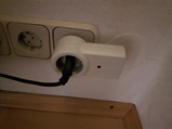
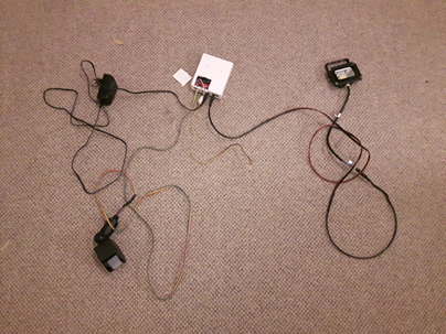
I built my serial device for mysensor in a box to control wireless sockets….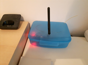
This is running since a year and my lights in the livingroom are automatically turned on and off according to sunrise and sunset. Nice. First goal.
I had issues with new versions of pimatic and the mysensors lib, but I could work it out.
Then I started to built a wireless motion sensor in a PIR of Ikea. (MOLGAN)
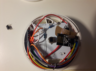
I had to learn what a LDR is, read about current dividers and so on… Hard topics for a beginner.
Then I started with the system for my parents.
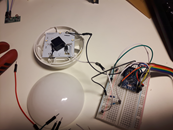
I started to built a station with 2 PIRS, 2 Relays to control a different 12V LED-Supply and some temperature sensors.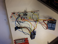
But I realized that all this soldering with wires takes too much time or is not that nice. So somebody told me make your own PCB.
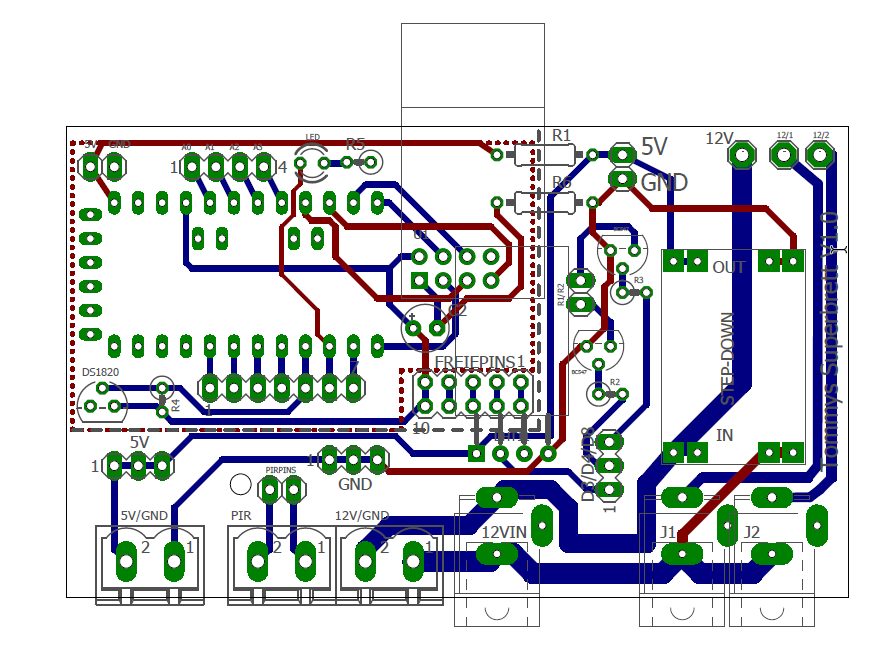
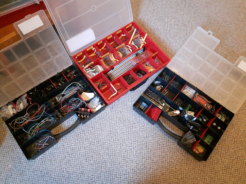
So I learned EAGLE and built my first PCB. I sent it to a PCB-Maker and Tataaa. There they are:

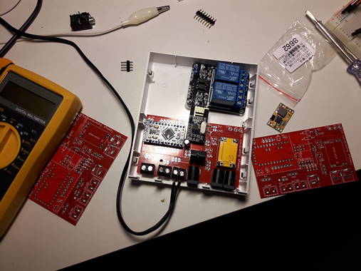
I built the PCBs in a way, I could divide them for smaller applications. The most important for me was the easy to built Arduino-Radio-Section. It has the most connections. The rest is easy.
So I’m using this PCB now for all things. Even for little wireless temperature sensors.
For the PIR-Relay-Temp-Stations I used NTBA-Cases that I found.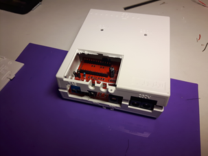
They are quite nice. And cheap.
So at the end I had two individual PIR-Relay-Stations. And everything is controlled with Pimatic by rules.
Even my worker desk changed. My wife gave me a nice Soldering Station for a present and within one year my arsenal of electronic pieces grew…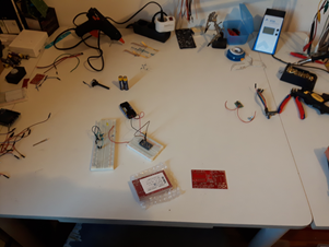
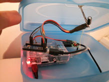
My current project is a battery-powered Temp-Sensor.
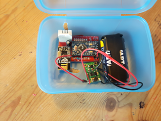
Again I’m using a part of the cutted PCB.
But I#m having problems with the radio. This little friend is 50m away from the main station.
And it is not connecting.
My questions:- What is a good orientation for the radio part? Vertical ---- or horicontal: | Antenna |
- How is repeating working? Do I just activate one sensor in between as a repeater and wait?
- IS there any order of adding a new sensor? Kind of binding sequence? First have it near the main station? Or is a binding also possible through a repeater?
Thank you!
-
My Project - A Beginners travel….
To be honest. I underestimated this.My goal was: to built a system that can react to PIRs and turn lamps on and out.
My parents have a large garden which is really dark in the night. No light till now.
My plan was to built two Mysensor-Stations that have multiple PIRs attached. And multiple 12V LED.
Those lights should be turned on according to motion detected by the PIR. But the whole system should be able to be controlled by a central server and Frontend. E.g. a garden party and you don’t want the lights to go on or using all the pirs as a alarm station react on motion, turn on all lights, blinking, and sending a message to my mobile phone.
I decided to buy a raspberry and add Pimatic as a webfrontend to control everything.
I built my serial device for mysensor in a box to control wireless sockets….
This is running since a year and my lights in the livingroom are automatically turned on and off according to sunrise and sunset. Nice. First goal.
I had issues with new versions of pimatic and the mysensors lib, but I could work it out.
Then I started to built a wireless motion sensor in a PIR of Ikea. (MOLGAN)
I had to learn what a LDR is, read about current dividers and so on… Hard topics for a beginner.
Then I started with the system for my parents.
I started to built a station with 2 PIRS, 2 Relays to control a different 12V LED-Supply and some temperature sensors.But I realized that all this soldering with wires takes too much time or is not that nice. So somebody told me make your own PCB.
So I learned EAGLE and built my first PCB. I sent it to a PCB-Maker and Tataaa. There they are:
I built the PCBs in a way, I could divide them for smaller applications. The most important for me was the easy to built Arduino-Radio-Section. It has the most connections. The rest is easy.
So I’m using this PCB now for all things. Even for little wireless temperature sensors.
For the PIR-Relay-Temp-Stations I used NTBA-Cases that I found.They are quite nice. And cheap.
So at the end I had two individual PIR-Relay-Stations. And everything is controlled with Pimatic by rules.
Even my worker desk changed. My wife gave me a nice Soldering Station for a present and within one year my arsenal of electronic pieces grew…My current project is a battery-powered Temp-Sensor.
Again I’m using a part of the cutted PCB.
But I#m having problems with the radio. This little friend is 50m away from the main station.
And it is not connecting.
My questions:- What is a good orientation for the radio part? Vertical ---- or horicontal: | Antenna |
- How is repeating working? Do I just activate one sensor in between as a repeater and wait?
- IS there any order of adding a new sensor? Kind of binding sequence? First have it near the main station? Or is a binding also possible through a repeater?
Thank you!
@segelmann Great to see you are having fun on your Mysensors journey.
A reliable connection to your nodes is a most important piece of a Mysensors setup. This becomes very apparent when you start deploying light switches that require an immediate reaction once activated. There is nothing worse than to gather all your family around to show off your latest piece of node wizardry only to find it does not perform as expected every time.
For nodes that are to be on the fringes of range I use this mod to the antenna, In testing I have found it to make a worthwhile improvement to range.
For my outside network I used this method to first establish the reliable range from my gateway , then once my first repeater was established used the same method to place the next repeater within range of my first repeater.
By using the antenna mod and correct repeater placement I now have reliable connections to my nodes over 100m away from the gateway with just two repeater nodes. You will find that once you get clear of buildings you will get a sizeable increase in the distance that can be covered reliably.
There are a few things to remember with repeater nodes, you cannot use sleep or delay in their code as this will prevent them from working as a repeater. You should try and have the repeater node as high up as is practical and clear of surrounding walls etc that might impede their signal.
Nodes that are on the fringe of range from the gateway may still connect to the gateway instead of your repeater and thus still give you unstable results. To prevent this you can include the code below .
#define MY_PARENT_NODE_ID 11            // set this to your repeater node id
#define MY_PARENT_NODE_IS_STATIC  // this will force your node to use only the repeater
this must be added at the top of your sketch before #include <MySensors.h> and will instruct the node to use the repeater at all times. Of course you must ensure that the repeater is always available.
Hello! It looks like you're interested in this conversation, but you don't have an account yet.
Getting fed up of having to scroll through the same posts each visit? When you register for an account, you'll always come back to exactly where you were before, and choose to be notified of new replies (either via email, or push notification). You'll also be able to save bookmarks and upvote posts to show your appreciation to other community members.
With your input, this post could be even better 💗
Register Login