💬 MyMultisensors
-
@alexsh1
beautiful !
about pin change interrupt, that would be too bad, to be restricted to D2, D3 only :)
there are multiple howtos which show how to use them. mcu datasheet section is also interesting. not that hard, don't worry.
you'll need to clean the code above a bit to fit your sketch (variables etc). the counters on pinh and pinl were for tests, you can factorize a bit pir isr and use only one volatile variable for your trigger etc.Have fun
-
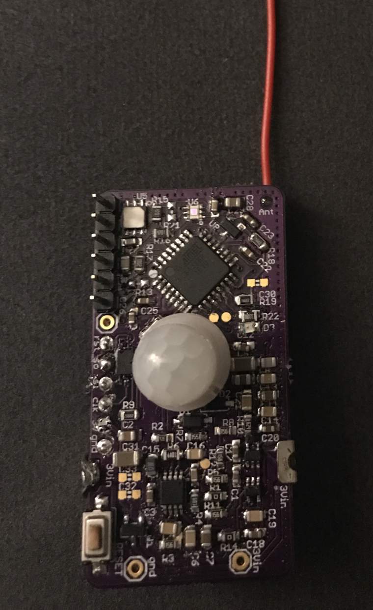
Here's my first 5 multi-sensors assembled and they've passed simple hardware tests. Although I think I have 2 that have PIRs that won't settle down. Thanks for the design scalz!
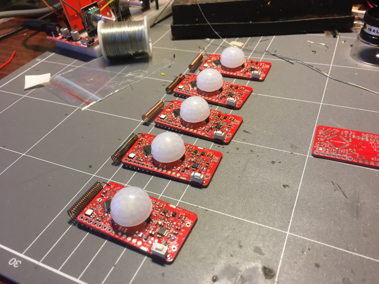
Now to write some firmware for them... Any hints? -
I've been slowly poking at these boards and I'm getting somewhere with the firmware, I should have something ready to put out there soon.
In the meantime though I designed a quick snap-together enclosure that I'm sending off for "Dirty" 3D printing:
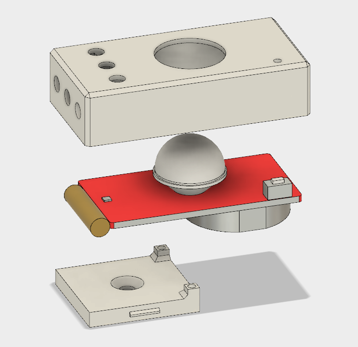
This is my first time using Fusion 360 and designing something for 3D printing, hopefully it goes okay.
I wanted it to snap together in two halves around the board and be as low-profile as possible, hence why the base plate only covers half of the PCB and is mounted by one screw only. I designed it around using a CR2450 battery. I might also see if I can find a small lens or light pipe to put over the lux sensor so it gets a better read on the light level in the room.
-
Okay, so here's some firmware I wrote for these multi-sensors: https://github.com/carywin/MySensors/tree/master/MyS_MultiSensor_revB
Note that I'm currently using MySensors 2.2-beta from the development branch, to solve the some other problems I was having in my RFM69-based gateway. This sketch should still work fine with the released version of MySensors but I haven't tested it.I'm still testing and refining things here and there, but it should be a working base for people to build from. Of course you will need to change the MySensors #defines to match your network and radio settings.
You'll probably notice that all of the sensors report under the same Child ID as a "Custom Sensor". This is because I'm using OpenHAB via an MQTT broker, so I don't really care if a certain sensor type matches with its provided variable types. If you're using a different controller, you may have to re-jig the Child ID/Variable types to match the known-working sensors on your controller.
PIR Sensor:
The PIR sensor is interrupt driven and will send a message when it receives more than 5 pulses in less than 5 seconds. After triggering, the interrupt is disabled for 60 seconds. If it receives fewer than 5 pulses then approx. 5 seconds after the last pulse it will reset the pulse counter. For the first 30 seconds after power-on, the PIR interrupts are disabled to allow the signal conditioning circuit time to settle. All of these values are configurable in the sketch. Note that I'm using GreyGnome's EnableInterrupt library, which you'll need to get from their Github.Lux Sensor:
The lux level sensor will send a new reading to the controller when the lux reading moves outside a window threshold from the current reading, which is configurable in the sketch. It also takes a new reading after a certain period with no changes in lux, which is also configurable in the sketch.
Note that you'll need the specific version of the OPT3001 library from the above link copied into your libraries folder. I modified the library to spit out raw values and allow the setting of thresholds, so the lux sensor can do most of the heavy lifting with regards to monitoring light levels and flagging an interrupt when it changes. Note that when the lux readings are very low, such as around sunrise and sunset, the threshold values are fixed to prevent excessive lux sensor messages.Door Sensor:
The D3 pin input is set to trigger an interrupt on state change, which will send its new state to the controller on each change. It's pulled high by an on-board resistor so the input pullup is disabled to save energy.Temp & Humidity Sensor:
Temperature and humidity are read at regular intervals (default 10 min), and new values only sent if the they have changed by 0.1 degC or 1% RH. If a certain number of intervals pass with no change (default 3 hours) they will send new values anyway. This way the controller can expire their readings after 3 hours and ignore stale values, and you can get an indication that maybe your sensor has failed. The interval times are configurable in the sketch. I'm using the Adafruit SI7021 library which you can get from their Github.Battery:
Once a day by default the sensor will report battery voltage as a sensor, and remaining capacity as a percentage using the in-built reporting function. The full and empty thresholds as well as reporting interval are configurable in the sketch. Note that the method used to measure battery voltage has a large margin for error, but that this can mostly be calibrated out. For this reason you'll see a VCC calibration value that you should set by measuring each sensor's battery voltage with a multimeter, and comparing with its reported battery volts.WDT:
I'm using the WDT during the time when the code isn't asleep, with a timeout of 2 seconds. This should be more than enough to send all of the sensor messages needed each cycle, but I haven't extensively tested that. I included it because in revision A I was suffering some kind of unknown lock up that would keep the MC awake and drain the coin cell battery in just a few hours. Of course the WDT is used by the library for timing the sleep intervals, so it gets re-enabled each wake up.Because timing how long an Arduino has been asleep is difficult without a RTC, the sleep time may vary somewhat depending on how many interrupts the sensor receives. Each time the MC is woken from sleep by an interrupt, it reduces the amount of time it will sleep next time by 25%. In addition to this, if more than 25 interrupts occur before a new round of sensor readings are taken, then the interval will be declared over and the sensors read again. These are crude methods for timing but so far it seem to be reliable in that the sensor neither sleeps forever nor spams excessively when receiving realistic rates of interrupt.
I welcome any input people have on this project and ways that this might be improved.
-
I was wondering why didn't you use a open drain comparator and you could have or-ed your outputs using only one MCU pin ?
-
because there was already enough parts on board, for power consumption and wanted to save as much as i could with this design.
The prototype had it though, but i removed it because that was useless as there are more than enough pins for this on mcu. -
good answer ! it's not a good one for those of us that are less 'code gifted'. but anyway good work for the design.i would have to study how i can get it to work in code.
-
Does anybody know of a neat way to get this board to operate below 2.7V?
From some reading it seems like the Atmega328 chip doesn't like running a crystal oscillator below 2.7V, but should be happy running from internal clock source. It seems like this might cause problems with libraries or serial comms though. Does anyone have experience with this or can point me towards a bootloader that might work?
So far I've had a couple of these sensors fail after 2 months or so with battery volts around 2.65V. I was hoping for at least 12 months from a CR2450, but some of these sensors are sending >150 messages a day so I'd understand if it was shorter than that. Still, 2 months is not enough I think, and I hope I can tweak something to get it to work down to at least 2.0V, which might squeeze some more time out of it.
@Carywin hello.
By default the BOD is set at 2.7V so the atmega will enter a boot loop when reaching this voltage.
You need to update the fuses to set BOD at 1.8V or remove it (but it's better to keep one, o
In some rare case it could write data in the wrong place and mess with the bootloader code).
It's also necessary to update fuses if you want to use internal oscillator, it is less precise but you just need to use a lower baud rate when transferring sketches or debugging and you will be fine.
I also suggest you run at 1MHz as long as you have no heavy computing to do. From it humble experience with CR batteries I always have better battery life at 1MHz compared to 8MHz.Look for tutorials about updating bootloader, there's a topic somewhere here called "various optiboot bootloader's" with précompilés bootloaders at different frequencies.
You just need to put the file in the right directory after updating you boards.txt file and you can write bootloader from arduino interface. Fuses will be updated at the same time.To write bootloader don't worry about a programmer, just go the easy way with Arduino ISP sketch (in examples menu) on a nano, connect as explained in the many tutorials on the web (but use 3.3V for VCC to protect your radio), select "Arduino as ISP" as programmer and you're good to go :)
-
I usually use the MySensors Sensebender bootloader. It's 1.8V BOD and internal 8Mhz.
else like nca78 said there is this topic:
https://www.openhardware.io/view/33/Various-bootloader-files-based-on-Optiboot-62 -
Okay I played around with this tonight and had some struggles. I couldn't get serial uploading working on any of the Gert Sanders bootloaders, so I had to use Arduino as ISP and Upload via Programmer.
However since I have encryption enabled, I need the AES key in EEPROM before my nodes will work.
So I had to enable the fuse that prevents EEPROM being erased when programming.I experimented with using the 1 MHz oscillator option, but the sketch didn't run properly. It was sending 5-8 copies of every message at a very slow rate.
So now I'm trying the 8 MHz internal oscillator with BOD at 1.8 V to see if that works at a lower voltage than the crystal.
If anyone knows if MySensors works at 1 MHz, or what might cause it to send multiple copies of the same message, speak up please!
-
@scalz Can you please enlighten me re PIR? There are two inputs D6 and D7. I cannot understand why and how to manage them in a sketch? Previously, I only used one digital input.
@alexsh1
You need to use pinchange interrupts. I won't reinvent a howto, there are multiple on google, like the one from Gammon here
https://gammon.com.au/forum/?id=11488&reply=6#reply6pinchange can only detect toggle. it's up to you to detect the pin state in the interrupt routine.
Mysensors sleep() doesn't handle pinchange. so in this case, just use sleep(ms). and test for the irq flag when it wakes upIn a previous post, I extracted and showed you the few functions needed for this. I thought it was enough documented!
ISR (PCINT1_vect)
{
  if (digitalRead(AMBIANT_LIGHT_PIN))
    irqLight = false;
  else
    irqLight = true;
}

ISR (PCINT2_vect)
{
  if((PIND & (1 << PIND6)) == 0x40 ) {
	  myPirSensor.pirhCount++;
		myPirSensor.irqPir = true;
	}
  if((PIND & (1 << PIND7)) == 0x80 ) {
	  myPirSensor.pirlCount++;
		myPirSensor.irqPir = true;
	}
}

/* ======================================================================
Function: pirIntEnable
Purpose : Enable pin change for PIR interrupt
Input   : -
Output  : -
Comments:
====================================================================== */
void pirIntEnable()
{
  // Enable pin change for D6, D7
  PCMSK2 |= bit (PCINT22);
  PCMSK2 |= bit (PCINT23);
  PCIFR  |= bit (PCIF2);   // clear any outstanding interrupts
  PCICR  |= bit (PCIE2);   // enable pin change interrupts for D0 to D7
}
/* ======================================================================
Function: pirIntDisable
Purpose : Disable pin change for PIR interrupt
Input   : -
Output  : -
Comments:
====================================================================== */
void pirIntDisable()
{
  // Disable pin change for D6, D7
  PCICR  ^= bit (PCIE2);   // disable pin change interrupts for D0 to D7
}
/* ======================================================================
Function: lightIntEnable
Purpose : Enable pin change for OPT3001 interrupt
Input   : -
Output  : -
Comments:
====================================================================== */
void lightIntDisable()
{
  PCMSK1 |= bit (PCINT9);
  PCIFR  |= bit (PCIF1);   // clear any outstanding interrupts
  PCICR  |= bit (PCIE1);   // enable pin change interrupts for A0 to A5
}
/* ======================================================================
Function: Light_IntDisable
Purpose : Disable pin change for OPT3001 interrupt
Input   : -
Output  : -
Comments:
====================================================================== */
void lightIntDisable()
{
  PCICR  ^= bit (PCIE1);   // disable pin change interrupts
}
So if we add this, in the MySensors Motion example, as a very basic example, this should look like this:
(untested, no time, but it should be close or maybe working)// Enable debug prints // #define MY_DEBUG // Enable and select radio type attached #define MY_RADIO_NRF24 //#define MY_RADIO_NRF5_ESB //#define MY_RADIO_RFM69 //#define MY_RADIO_RFM95 #include <MySensors.h> uint32_t SLEEP_TIME = 120000; // Sleep time between reports (in milliseconds) #define PIR_SETTLE_TIME 300000 #define PIR_INT_PINH 6 // The digital input you attached your motion sensor. #define PIR_INT_PINL 7 // The digital input you attached your motion sensor. #define CHILD_ID 1 // Id of the sensor child // Initialize motion message MyMessage msg(CHILD_ID, V_TRIPPED); volatile bool irqPirHigh = false; /* ====================================================================== Pin change Interrupt Service Routine for D0 to D7 ====================================================================== */ ISR (PCINT2_vect) { // Pin change interrupt! // if one of the PIR pins is HIGH, we have a pulse if((PIND & (1 << PIND6)) == 0x40 || (PIND & (1 << PIND7)) == 0x80 ) { irqPirHigh = true; } } /* ====================================================================== Function: pirIntEnable Purpose : Enable pin change for PIR interrupt Comments: ====================================================================== */ void pirIntEnable() { // Enable pin change for D6, D7 PCMSK2 |= bit (PCINT22); PCMSK2 |= bit (PCINT23); PCIFR |= bit (PCIF2); // clear any outstanding interrupts PCICR |= bit (PCIE2); // enable pin change interrupts for D0 to D7 } /* ====================================================================== Function: pirIntDisable Purpose : Disable pin change for PIR interrupt Comments: ====================================================================== */ void pirIntDisable() { // Disable pin change for D6, D7 PCICR ^= bit (PCIE2); // disable pin change interrupts for D0 to D7 } /* ====================================================================== Function: before Purpose : set pin states Comments: before setup Mysensors init ====================================================================== */ void before() { hwDigitalWrite(PIR_INT_PINH, LOW); hwPinMode(PIR_INT_PINH, INPUT); // sets the motion sensor digital pinH as input hwDigitalWrite(PIR_INT_PINH, LOW); hwPinMode(PIR_INT_PINL, INPUT); // sets the motion sensor digital pinL as input } void setup() { // do setup stuff like waiting for pir to settle, send states at init etc. sleep(PIR_SETTLE_TIME); // enable pin change interrupt to enable PIR/motion detection pirIntEnable(); } void presentation() { // Send the sketch version information to the gateway and Controller sendSketchInfo("Motion Sensor", "1.0"); // Register all sensors to gw (they will be created as child devices) present(CHILD_ID, S_MOTION); } void loop() { // irq ? if (irqPirHigh) { // We got a HIGH pulse on PIR pins!! // increment a pulse counter, etc. // test pulse counter then send or not send(msg.set("1")); irqPirHigh = false; } else { // increment timer counters, to reset motion state etc // do stuff } // Sleep until timer or a pin change interrupt sleep(SLEEP_TIME); Serial.println("Wake up!"); }Remember it detect pin change, so it will wake up at each pin change state.
I can't make this example more noob and simple. then add all your variables for states, timers, improve power consumption etc, as you wish.Or, it's perhaps easier to use the example from carywinn above. he posted his sketch which use a lib to handle pinchange. (on my side I don't need a lib for this, and it also saves memory).
I hope it's clear about pinchange, so I'm done at explaining it ;)
-
@alexsh1
You need to use pinchange interrupts. I won't reinvent a howto, there are multiple on google, like the one from Gammon here
https://gammon.com.au/forum/?id=11488&reply=6#reply6pinchange can only detect toggle. it's up to you to detect the pin state in the interrupt routine.
Mysensors sleep() doesn't handle pinchange. so in this case, just use sleep(ms). and test for the irq flag when it wakes upIn a previous post, I extracted and showed you the few functions needed for this. I thought it was enough documented!
ISR (PCINT1_vect)
{
  if (digitalRead(AMBIANT_LIGHT_PIN))
    irqLight = false;
  else
    irqLight = true;
}

ISR (PCINT2_vect)
{
  if((PIND & (1 << PIND6)) == 0x40 ) {
	  myPirSensor.pirhCount++;
		myPirSensor.irqPir = true;
	}
  if((PIND & (1 << PIND7)) == 0x80 ) {
	  myPirSensor.pirlCount++;
		myPirSensor.irqPir = true;
	}
}

/* ======================================================================
Function: pirIntEnable
Purpose : Enable pin change for PIR interrupt
Input   : -
Output  : -
Comments:
====================================================================== */
void pirIntEnable()
{
  // Enable pin change for D6, D7
  PCMSK2 |= bit (PCINT22);
  PCMSK2 |= bit (PCINT23);
  PCIFR  |= bit (PCIF2);   // clear any outstanding interrupts
  PCICR  |= bit (PCIE2);   // enable pin change interrupts for D0 to D7
}
/* ======================================================================
Function: pirIntDisable
Purpose : Disable pin change for PIR interrupt
Input   : -
Output  : -
Comments:
====================================================================== */
void pirIntDisable()
{
  // Disable pin change for D6, D7
  PCICR  ^= bit (PCIE2);   // disable pin change interrupts for D0 to D7
}
/* ======================================================================
Function: lightIntEnable
Purpose : Enable pin change for OPT3001 interrupt
Input   : -
Output  : -
Comments:
====================================================================== */
void lightIntDisable()
{
  PCMSK1 |= bit (PCINT9);
  PCIFR  |= bit (PCIF1);   // clear any outstanding interrupts
  PCICR  |= bit (PCIE1);   // enable pin change interrupts for A0 to A5
}
/* ======================================================================
Function: Light_IntDisable
Purpose : Disable pin change for OPT3001 interrupt
Input   : -
Output  : -
Comments:
====================================================================== */
void lightIntDisable()
{
  PCICR  ^= bit (PCIE1);   // disable pin change interrupts
}
So if we add this, in the MySensors Motion example, as a very basic example, this should look like this:
(untested, no time, but it should be close or maybe working)// Enable debug prints // #define MY_DEBUG // Enable and select radio type attached #define MY_RADIO_NRF24 //#define MY_RADIO_NRF5_ESB //#define MY_RADIO_RFM69 //#define MY_RADIO_RFM95 #include <MySensors.h> uint32_t SLEEP_TIME = 120000; // Sleep time between reports (in milliseconds) #define PIR_SETTLE_TIME 300000 #define PIR_INT_PINH 6 // The digital input you attached your motion sensor. #define PIR_INT_PINL 7 // The digital input you attached your motion sensor. #define CHILD_ID 1 // Id of the sensor child // Initialize motion message MyMessage msg(CHILD_ID, V_TRIPPED); volatile bool irqPirHigh = false; /* ====================================================================== Pin change Interrupt Service Routine for D0 to D7 ====================================================================== */ ISR (PCINT2_vect) { // Pin change interrupt! // if one of the PIR pins is HIGH, we have a pulse if((PIND & (1 << PIND6)) == 0x40 || (PIND & (1 << PIND7)) == 0x80 ) { irqPirHigh = true; } } /* ====================================================================== Function: pirIntEnable Purpose : Enable pin change for PIR interrupt Comments: ====================================================================== */ void pirIntEnable() { // Enable pin change for D6, D7 PCMSK2 |= bit (PCINT22); PCMSK2 |= bit (PCINT23); PCIFR |= bit (PCIF2); // clear any outstanding interrupts PCICR |= bit (PCIE2); // enable pin change interrupts for D0 to D7 } /* ====================================================================== Function: pirIntDisable Purpose : Disable pin change for PIR interrupt Comments: ====================================================================== */ void pirIntDisable() { // Disable pin change for D6, D7 PCICR ^= bit (PCIE2); // disable pin change interrupts for D0 to D7 } /* ====================================================================== Function: before Purpose : set pin states Comments: before setup Mysensors init ====================================================================== */ void before() { hwDigitalWrite(PIR_INT_PINH, LOW); hwPinMode(PIR_INT_PINH, INPUT); // sets the motion sensor digital pinH as input hwDigitalWrite(PIR_INT_PINH, LOW); hwPinMode(PIR_INT_PINL, INPUT); // sets the motion sensor digital pinL as input } void setup() { // do setup stuff like waiting for pir to settle, send states at init etc. sleep(PIR_SETTLE_TIME); // enable pin change interrupt to enable PIR/motion detection pirIntEnable(); } void presentation() { // Send the sketch version information to the gateway and Controller sendSketchInfo("Motion Sensor", "1.0"); // Register all sensors to gw (they will be created as child devices) present(CHILD_ID, S_MOTION); } void loop() { // irq ? if (irqPirHigh) { // We got a HIGH pulse on PIR pins!! // increment a pulse counter, etc. // test pulse counter then send or not send(msg.set("1")); irqPirHigh = false; } else { // increment timer counters, to reset motion state etc // do stuff } // Sleep until timer or a pin change interrupt sleep(SLEEP_TIME); Serial.println("Wake up!"); }Remember it detect pin change, so it will wake up at each pin change state.
I can't make this example more noob and simple. then add all your variables for states, timers, improve power consumption etc, as you wish.Or, it's perhaps easier to use the example from carywinn above. he posted his sketch which use a lib to handle pinchange. (on my side I don't need a lib for this, and it also saves memory).
I hope it's clear about pinchange, so I'm done at explaining it ;)
@scalz said in 💬 MyMultisensors:
uint32_t SLEEP_TIME = 120000; // Sleep time between reports (in milliseconds)
You are a star - I must admit that setting it up is a bit more fiddly. This is the first time I come across pinchange interrupts and excellent link you provided. Thank you
Hello! It looks like you're interested in this conversation, but you don't have an account yet.
Getting fed up of having to scroll through the same posts each visit? When you register for an account, you'll always come back to exactly where you were before, and choose to be notified of new replies (either via email, or push notification). You'll also be able to save bookmarks and upvote posts to show your appreciation to other community members.
With your input, this post could be even better 💗
Register Login