nRF5 action!


  • @NeverDie exactly! On top, they have very extensive datasheet with all the results


  • Hero Member

    I just now noticed that fanstel is selling an nRF52840 module: http://www.fanstel.com/buy/bt840f-v1-nrf52840-bluetooth-5-thread-zigbee-module

    That's the first I've seen on the open market (aside from the DK that is). [Edit: won't be shipping until January though]

    I wonder which, if any, of the Fanstel modules contain the DCDC hardware? Their pinout on the 832's does not appear to be as complete as the Ebyte module, so if DCDC is not already on the module, it might be impossible to add after-the-fact.


  • @NeverDie said in nRF5 Bluetooth action!:

    Their pinout on the 832's does not appear to be as complete as the Ebyte module, so if DCDC is not already on the module, it might be impossible to add after-the-fact.

    https://static1.squarespace.com/static/561459a2e4b0b39f5cefa12e/t/59a5a0bbbe42d6d26bd82969/1504026813812/BlueNor_BT840F_datasheets.pdf

    Page 13,
    pin F5


  • Hero Member

    @Toyman Thanks! I'm going to order a couple of the Nordic nRF52840 PDK's to audition now that modules are on the horizon. Shall be interesting to see how the range compares in a normal home environment. Also, 256K RAM and 1M of flash sounds like such a luxury!


  • @NeverDie Note that all the nRF52840 based products being showcased now (including the Fanstel modules) are using the engineering silicon. There is Errata on these parts. Production devices will be available Q1-18.


  • Hero Member

    @Jokgi said in nRF5 Bluetooth action!:

    @NeverDie Note that all the nRF52840 based products being showcased now (including the Fanstel modules) are using the engineering silicon. There is Errata on these parts. Production devices will be available Q1-18.

    Do you advise waiting, or is it sufficiently non-buggy that it's likely to work unless doing something obscure?


  • Hero Member

    @d00616 Problem #1 is that there does not yet appear to be an Arduino board definition for the nR5F2840, as there is already for the nRF52832 and nRF51822. Is that correct? Or does one already exist somewhere? It's critical path to testing code on the nRF52840 PDK.


  • Hero Member

    Hmmm... Looks like there is an nRF52840 "variant": https://github.com/lpercifield/arduino-nRF5/commit/d55d54a1bdc479acc259e131f0f445c5da8e02b3
    Would that work? If so, how exactly should it be added so that it will appear in the Arduino IDE board manager list of boards?


  • @NeverDie the main issue it's "65 commits behind master" so it's outdated in all areas except 840
    Theoretical path is to make a fork of current sandeep's branch and then merge the changes from the repository you found. But given the above, it won't be easy.


  • Hero Member

    Gosh, I'm wishing now that I hadn't ordered the PDK. I guess I'll just return it for a refund. Since it sounds like literally no one else is presently using the 840, I'd rather move forward on the 832. I'm more interested in the 2mbps datarate anyway (for the reason below). And I'm pretty sure PA versions of the nRF52832 will beat the range of an unamplified nRF52840.


  • Hero Member

    @d00616 said in nRF5 Bluetooth action!:

    Great job. If I'm not wrong the method allows nearly 1 year of listening time with a CR2032.

    Yup, based on the latest measurements, I estimate an average current drain of about 25 microamps. So, assuming a CR2032 has 240mah of useable current, that comes out to about 1.1 years of listening time. Or more than 13 years on a pair of Energizer Lithium AA's. Pretty cool. 🙂 And that's listening for a packet once every 100ms. It could last much longer if it were to listen less often.


  • Hardware Contributor

    @NeverDie said in nRF5 Bluetooth action!:

    Gosh, I'm wishing now that I hadn't ordered the PDK. I guess I'll just return it for a refund. Since it sounds like literally no one else is presently using the 840, I'd rather move forward on the 832. I'm more interested in the 2mbps datarate anyway (for the reason below). And I'm pretty sure PA versions of the nRF52832 will beat the range of an unamplified nRF52840.

    I looked at the fanstel modules a while ago, but like guys said above, these are beta mcus with errata. And not arduino uptodate for the same reason i guess.

    I have one 840pdk too. for tests 🙂 with apache mynewt. Because I have only one 840 board I can't tell you about the range because it needs two boards for checking that, two boards with full BLE5 Long range (and 832 is not BLE5 full range).

    No idea about 840 vs 832+PA but 840 is already PA integrated which is pretty cool. It also has some other nice features. Range tests regarding BLE5 long range are impressive imho, indoor or not, and from different mcu manufacturers (some have nice parts).
    I'm not sure though, if 840, is compatible with NRF24. And, as I'm talking about BLE, I prefer to say it again, for others.. BLE is not MySensors 🙂


  • Hero Member

    Are there any examples of how to control the potential BLE5 capabilities of this chip using code developed in the Arduino IDE? I recognize that it's presently a separate thing from MySensors, which is using the proprietary modes to ensure backward compatability to the nRF24, but surely getting some hooks into BLE5--even if it's just high level stuff--would be beneficial wouldn't it?


  • Hero Member

    For instance, how hard would it be to create a simple serial bridge so view serial output on your bluetooth phone, the way @sundberg84 is doing with a specialized bluetooth module: https://forum.mysensors.org/topic/6340/debug-to-a-sd-card-module


  • Contest Winner

    @NeverDie said in nRF5 Bluetooth action!:

    For instance, how hard would it be to create a simple serial bridge so view serial output on your bluetooth phone, the way @sundberg84 is doing with a specialized bluetooth module: https://forum.mysensors.org/topic/6340/debug-to-a-sd-card-module

    For similar functionality, there is an MY_DEBUG_OTA feature in MySensors development branch. You can send log messages to any node in the MySensors network.

    The NRF5 MySensors port is running directly on the MCU hardware. Using the SoftDevice is like running an Operating System. There are limitations using the Hardware and APIs have to use. You are loosing control over the Radio, some Timers and RTC, Crypto components and the memory layout.

    The reason the SoftDevice isn't supported is the old licence model. This model is changed with SDK14.

    In my opinion with MySensors 2.x it isn't meaningful to play with the multiplexing of the radio module. I think this requires more changes in MySensors to handle the time when the MCU is in BLE mode.

    If you are interested implementing a dual stack software, then I think the Arduino Primo port is a good point to start. This is based on the NRF5 SDK. The Primo port has no support for NRF51 devices.

    If you are not restricted to Arduino, you can also see MyNewt or Zephyr. Both have BLE Open Sorurce implementations for the NRF5 MCUs.


  • Hardware Contributor

    I agree with @d00616 points above.
    And, sure bluetooth would be nice for interacting or debugging.

    In my opinion, maybe I'm wrong, for my network, I would prefer MySensors NRF ESB, in general.

    • "more secure" than bluetooth. "harder" to access Mysensors ESB than bluetooth for example, plus some security issue that can happen with bluetooth, phones..
    • more devices in a network

  • Hero Member

    @d00616 What do you foresee regarding the nRF52840? It's presently unsupported.


  • Hero Member

    For those who haven't seen it, this Fanstel nRF52832 module is impressively small:
    alt text
    Looks as though it even includes the antenna!


  • Hero Member

    Good news. The Fanstel 832X (https://static1.squarespace.com/static/561459a2e4b0b39f5cefa12e/t/59a5a03d579fb36451a25f01/1504026688443/BlueNor_BT832X_datasheets.pdf) module contains the sky66112 (http://www.skyworksinc.com/Product/3152/SKY77927-11z-. which has a PA and an LNA on it. The Rx gain is 11dB, and the TX gain is 22dB. So, this should make for a very good gateway module.


  • @NeverDie they even provide a piece of code to properly activate it


  • Contest Winner

    @NeverDie said in nRF5 Bluetooth action!:

    @d00616 What do you foresee regarding the nRF52840? It's presently unsupported.

    In those places where it was obvious, I took the design of the NRF52840 into consideration. I think, when an Arduino port supporting Sketches without SoftDevices is available, then porting is simple. At the moment, I have no plans to expedite an Arduino port.


  • @d00616 said in nRF5 Bluetooth action!:

    when an Arduino port supporting Sketches without SoftDevices is availableI

    I doubt it will ever happen as all 3 major nrf5 arduino implementations all rely on Softdevice (Primo, Adafruit and Sandeep)


  • Hero Member

    @Toyman said in nRF5 Bluetooth action!:

    I doubt it will ever happen as all 3 major nrf5 arduino implementations all rely on Softdevice (Primo, Adafruit and Sandeep)

    I don't follow what you mean. Aren't we already running the MySensors code without installing the softdevice on the nrf51822 and the nrf52832?


  • @NeverDie Sorry, I meant "BLE implementation without Softdevice"


  • Hero Member

    @d00616 said in nRF5 Bluetooth action!:

    when an Arduino port supporting Sketches without SoftDevices is available

    Is it Sandeep who does that port, or you, or...? I don't have a clear picture as to how many people are working on it, or even who is doing what.


  • Hero Member

    @Toyman said in nRF5 Bluetooth action!:

    @NeverDie Sorry, I meant "BLE implementation without Softdevice"

    I guess the way I read this fog of tea leaves is that nothing is going to happen before final silicon on the nRF52840, and even then there's not much motivating an Arduino port for it. And someday it may happen. i.e. I guess the folks who are doing the heavy lifting are generally happy with the nRF52832 and its capabilities? I probably wouldn't be comfortable relying purely on the nRF52832 if it weren't for the amplified modules that fill the gap. I haven't tried the Fanstel one, but on paper it looks like it's probably good enough for my modest needs.


  • @NeverDie Are you talking about MYS or in general? Because, currently there are two completely different approaches to nrf-arduino. One is based on softdevice (or in broader terms, on SDK) while another works direcly with hardware.
    For MYS, our only hope is d00616, if he doesn't do it, chances somebody will apapt 52840 to MYS are negligible.
    Frankly, MYS don't need it, but that's just my opinion.


  • Contest Winner

    @Toyman said in nRF5 Bluetooth action!:

    For MYS, our only hope is d00616, if he doesn't do it, chances somebody will apapt 52840 to MYS are negligible.

    Please don't be so pessimistic. I expect some very small changes to MySensors to support the NRF52840 platform when arduino-nrf5 is ported to the new NRF5 MCU generation. When arduino-nrf5 supports the NRF52840 platform, I do some tests with the 840DK, I already have.

    Looking back to the NRF52832, I think in 6-9 month we can buy NRF52840 modules with production ready chips. I think there is no reason for panic.


  • Hero Member

    @Toyman
    D00616's explanation increases my optimism considerably because: the people doing the NRF-arduino port care a lot about bluetooth. They'll want to see it through for that reason, because the 840 has much more bluetooth capabilities. Then, once they get that part done, like D00616 says, it will be ripe for porting to MYS. So really, all the interests are aligned. I don't think it will languish. At least, that's the narrative I'm going with.


  • Hero Member

    Received this today:
    0_1508192352279_RFaxis.jpg
    I thought it might have the same PA-LNA as the sky66112 (which also supports antenna diversity) used on the Fanstel, but the lettering suggests otherwise.


  • Hero Member

    Here's a better close-up of the chips themselves, which is easier to read:
    0_1508192892369_RFaxis2.jpg


  • Hero Member


  • @NeverDie As I may have mentioned before. This was a limited run of prototypes (100 total) designed by RF AXIS and built by Xungtong.. My understanding is that this device is being deemphasized by Skyworks in favor of the SKY661xx family..


  • Hero Member

    @Jokgi
    Do you happen to have the datasheet? The closest I've been able to find is: http://www.mouser.com/ds/2/472/rfaxis_RFX2411N Eval Board Summary and Technical N-952564.pdf
    which isn't quite on-point, but I may have to make do with.

    I had thought it would somehow automagically select the better antenna for receiving, but it looks like it wants me to make that selection myself. So, this may work better with longer preambles I suppose, to give enough time to measure the RSSI on each and then decide.


  • @NeverDie The datasheet for the RFX2411N?


  • @Jokgi The only datasheet I have states that it is confidential. Therefore I cannot share it. However if you contact Skyworks they may be able to get you a copy. At the time I received it one needed to fill out a form on RF Axis site and then the file would be sent. Are there any particular parameters you are interested in?


  • Hero Member

    @Jokgi

    Just which pins on the nRF52832 are connected to which control pins on the RF Front End. I just now checked with a continuity meter, and it looks like none of them are. So, it would appear that I'll need to wire the pin connections external to the PCB, which is weird, but maybe that's just how it is.


  • Hardware Contributor

    @scalz said in nRF5 Bluetooth action!:

    In my opinion, maybe I'm wrong, for my network, I would prefer MySensors NRF ESB, in general.

    • more devices in a network

    Not with bluetooth mesh, you can have thousands of nodes 😉


  • @NeverDie Hello, If you are referring to that Prototype Board with the Nordic logo on it then it was being controlled by GPIO and by the Bluetooth Low Energy stack (Softdevice) You can read more about it here.. https://devzone.nordicsemi.com/blogs/831/palna-support-in-s132/.
    As I mentioned before. there is no good way to control the PA in a proprietary mode, only when using BLE. Regardless, I have asked if it is ok to share the schematic that relates to that PA board and I will let you all know. And about the question about antenna switching. This was never implemented in the Softdevice. Any antenna switching would need to be done in the application.
    See if this chart helps.

    0_1508212131505_I-O for nRF52832 - RFX2411n.JPG


  • Hardware Contributor

    @Nca78 said in nRF5 Bluetooth action!:

    Not with bluetooth mesh, you can have thousands of nodes 😉

    not without some latency 🙂
    but I agree, I forgot this new mode 👍
    I just prefer to keep my nodes "hidden" for security. so no BLE network for me. I will just have some restricted access to it I think..


  • Hero Member

    @Jokgi
    Thanks! Yes, those three tables are exactly what I was looking for.


  • Hero Member


  • Hero Member

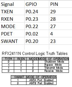
    I just noticed a very clever thing that Fanstel did: their nRF52 modules all have the same land pattern and pinout. That means you can upgrade from a regular nRF52832 to a power amplified version, or even an NRF52840 (when they become available), by just dropping the upgrade module into the same position on the PCB. i.e. you can run all the different modules from the same PCB design. Pretty cool. I like it. 🙂


  • Mod

    @NeverDie but how will you spend all the time you save by not having to create new boards all the time? 😉


  • Hero Member

    @mfalkvidd said in nRF5 Bluetooth action!:

    @NeverDie but how will you spend all the time you save by not having to create new boards all the time? 😉

    Yeah, not just that, but also not having to waste all that time waiting for each new board to come back from the fab. 🙂


  • Hero Member

    @NeverDie said in nRF5 Bluetooth action!:

    I had thought it would somehow automagically select the better antenna for receiving, but it looks like it wants me to make that selection myself. So, this may work better with longer preambles I suppose, to give enough time to measure the RSSI on each and then decide.

    I suppose an easy solution would be to have a remote node send repeated packets, and I just program the RFAxis to toggle between its two antennas after allowing sufficient dwell time per antenna. That way it's more likely to receive at least one of the packets.

    All in all, though, I think maybe having two separate radio receivers (since they're cheap anyway) for a gateway is probably better than having one radio receiver, with the burden on the firmware to select which antenna to receive on.

    Any thoughts on this?


  • @NeverDie 0_1508367805179_RD-nRF52-RFX2411N-REV2.zip Hello All -- For your viewing enjoyment. The Schematic and layout files for that nRF52840 and RFX2411n board you have. (If it is version 2 which did have the big Nordic logo on it. )
    I think you may know this already but this bears repeating. This is not a Nordic board. Nordic Semiconductor's tech support will probably not know anything about this board. Also there is a difference between the RFX2411 and the nRF2411N. (N for Nordic) It is not the same device.


  • Hero Member

    On a different topic, regarding the Ebyte modules, I'm noticing that they are much more likely to miss a packet if being run at 2.1v than if it's being run at, say, 3.3v. I've tried this now on two different modules, and the results are repeatable. It's a preliminary result, because so far I've only tested it with respect to the "listen mode."


  • @NeverDie Is this the board with a PA on it or stand alone nRF5x part? If with a PA what is the rated voltage of the device?

    Depending on the Nordic part the nRF5x can run from 1.7 (or 1.8) to 3.6vdc. Note that the nRF51 cannot run with the DC / DC under 2vdc. The nRF52 does not have that restriction and the DC/DC can be used throughout the full voltage range..


  • Hero Member

    @Jokgi said in nRF5 Bluetooth action!:

    Is this the board with a PA on it or stand alone nRF5x part?

    I observed it on Ebyte's E73-2G4M04S on this board: https://www.openhardware.io/view/471/Ebyte-nRF52832-Small-Breakout-Board
    while running in DCDC mode. The E73-2G4M04 has no PA.

    For now, I'm just reporting the finding, in case anyone else has noticed it. Also, it's a very early result. If there's no known reason to suspect the nRF52832 as a possible cause (i.e. no erratas or the like), then I'm glad to hear it.


  • Hero Member

    OK, I fixed the problem by increasing the size of the listen window by another 30 microseconds (which is the smallest granularity that the RTC offers). What this probably means is that some aspect of the wake-up process (for instance, perhaps the amount of time it takes for the high frequency oscillator to come up to speed) is taking a wee bit longer when the module is powered at the lower voltage than when it is powered at 3.3v.


  • Hero Member

    @Jokgi said in nRF5 Bluetooth action!:

    @NeverDie Hello, If you are referring to that Prototype Board with the Nordic logo on it then it was being controlled by GPIO and by the Bluetooth Low Energy stack (Softdevice) You can read more about it here.. https://devzone.nordicsemi.com/blogs/831/palna-support-in-s132/.
    As I mentioned before. there is no good way to control the PA in a proprietary mode, only when using BLE. Regardless, I have asked if it is ok to share the schematic that relates to that PA board and I will let you all know. And about the question about antenna switching. This was never implemented in the Softdevice. Any antenna switching would need to be done in the application.
    See if this chart helps.

    0_1508212131505_I-O for nRF52832 - RFX2411n.JPG

    The only definition I've found for PDET is "Analog Voltage Proportional to the PA Power Output ." I'm not sure what that means. So, I set P0.02 to HIGH, which in this instance is 3.3v. However, I'm only getting relatively weak Tx power emitted. Is there anything else I should be doing? For instance, should I be supplying external voltage to the PDET pin directly?

    Here's the code I'm currently using to setup for transmission:

      myNrf5_pinMode(2,OUTPUT_H0H1); //PDET
      myNrf5_pinMode(20,OUTPUT_H0H1); //SWANT
      myNrf5_pinMode(24,OUTPUT_H0H1); //TXEN   
      myNrf5_pinMode(23,OUTPUT_H0H1); //RXEN
      myNrf5_pinMode(22,OUTPUT_H0H1); //MODE
    
      digitalWrite(20,HIGH);  //select one of the antenna's.
      digitalWrite(23,LOW);  //disable RXEN
      digitalWrite(24,HIGH);  //enable TXEN
      digitalWrite(22,LOW);  //disable MODE
      digitalWrite(2,HIGH);  //set the analog voltage for PDET as high as possible
    

  • Hero Member

    @NeverDie said in nRF5 Bluetooth action!:

    For instance, should I be supplying external voltage to the PDET pin directly?

    I tried that just now, and it made no difference.

    I also tried powering the PA_VDD pin externally at 3.3v, and that didn't help either. Does that pin expect higher voltages?


  • Hero Member

    @Jokgi said in nRF5 Bluetooth action!:

    @NeverDie 0_1508367805179_RD-nRF52-RFX2411N-REV2.zip Hello All -- For your viewing enjoyment. The Schematic and layout files for that nRF52840 and RFX2411n board you have. (If it is version 2 which did have the big Nordic logo on it. )
    I think you may know this already but this bears repeating. This is not a Nordic board. Nordic Semiconductor's tech support will probably not know anything about this board. Also there is a difference between the RFX2411 and the nRF2411N. (N for Nordic) It is not the same device.

    Just now noticed that the schematic explains PDET. It's "Optional Antenna Power Monitoring." So, I take that to mean that it's output from the board, not input to it.

    Also, the schematic indicates that the board has the DCDC inductors built into it, so that's good.


  • Hero Member

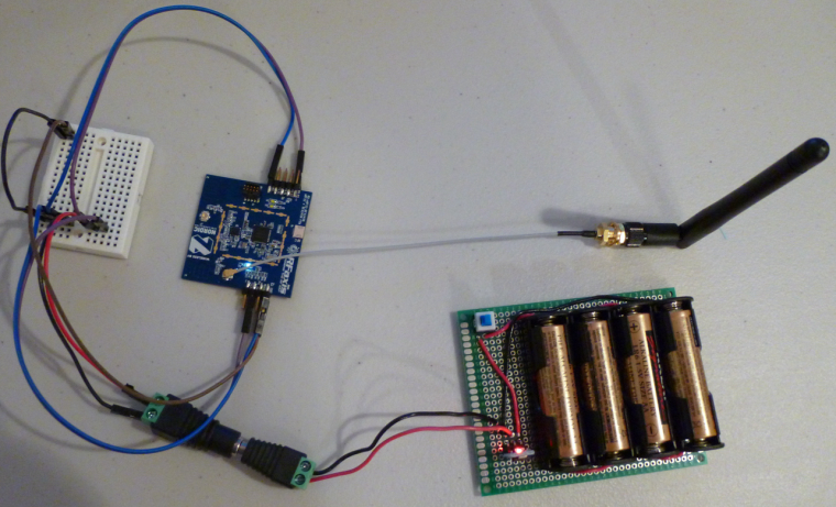
    Aha! Apparently the RFaxis defaults not to the trace antenna on the board, but rather to the external, connected antenna. So, I hooked that up, and now it's working like a champ. I can now safely say that it definitely has a much better range than a non-PA nRF52832 module. And, of course, I'm running it at 2mbps. 🙂

    The other nice thing is that even if I transmit continuously (i.e. 100% duty Tx cycle), the chips don't get hot. I'm impressed. I tried doing that with a LoRa module once, and it got too hot to even touch.

    It will be fun to check the range when there's a PA+LNA nRF52832 on both ends of the link.


  • Hero Member

    And here it is:
    0_1508440744687_RFaxis3.jpg


  • Hero Member

    Of course, I couldn't stop until I tried hooking it up to the 4w boost amplifier:
    0_1508445375879_RFaxis4.jpg
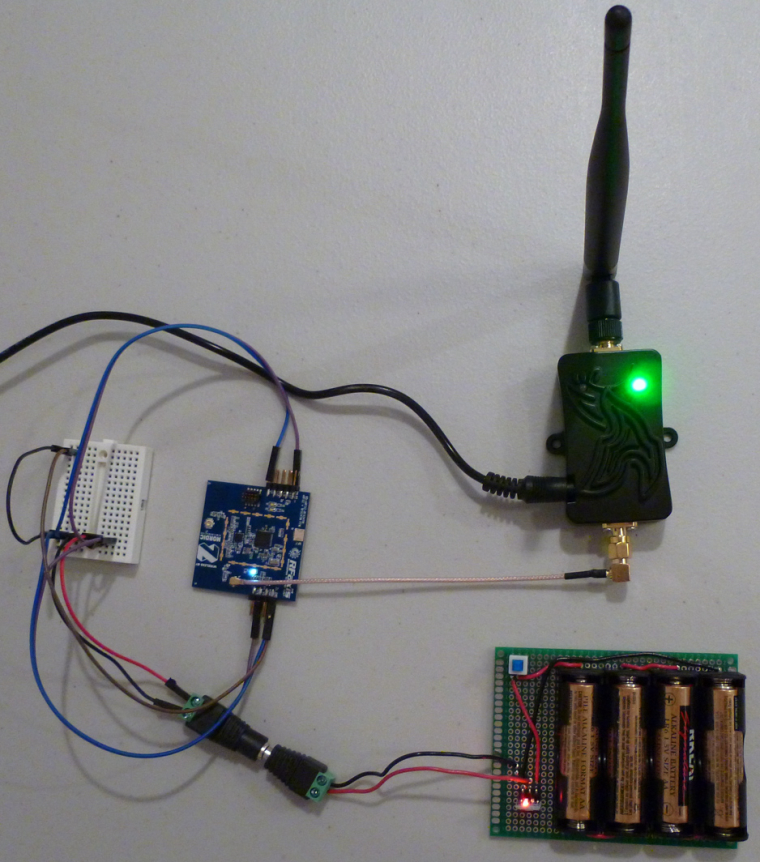
    Wow! That really kicks tail. I don't think there's a nook or cranny anywhere that I don't get a great signal now, and all from a single gateway. 🙂


  • Hero Member

    I just now ordered a number of Fanstel modules to go with the breakout boards I recently posted. It's worth noting that Fanstel's lowest cost nRF52832 module is only $3.75, which is lower than the Ebyte module: http://www.fanstel.com/buy/bt832-ble42-hardware-ready-for-bluetooth-5-module-2fhya
    I ordered one, and I'll see how it compares in actual use.


  • Hardware Contributor

    @NeverDie said in nRF5 Bluetooth action!:

    It's worth noting that Fanstel's lowest cost nRF52832 module is only $3.75, which is lower than the Ebyte module: http://www.fanstel.com/buy/bt832-ble42-hardware-ready-for-bluetooth-5-module-2fhya

    interesting for US customers only I think. Because last time I looked, shipping were too expensive (plus add extra shipping fee like customs etc.).


  • Hardware Contributor

    @NeverDie said in nRF5 Bluetooth action!:

    It's worth noting that Fanstel's lowest cost nRF52832 module is only $3.75, which is lower than the Ebyte module: http://www.fanstel.com/buy/bt832-ble42-hardware-ready-for-bluetooth-5-module-2fhya
    I ordered one, and I'll see how it compares in actual use.
    It's woth noting that despite it's "832" name it's in fact an nrf52810 😛

    @scalz said in nRF5 Bluetooth action!:

    interesting for US customers only I think. Because last time I looked, shipping were too expensive (plus add extra shipping fee like customs etc.).
    43$ shipping if you're not in the US. And with DHL meaning (at least for me) 10 extra dollars of DHL fee for custom processing + highest tax possible.


  • Hero Member


  • Hero Member

    It's too bad Fanstel's shipping rates outside the US are high. I received the modules I ordered from Fanstel in just a couple of days. I'll try them out after I receive the PCB's from OSH PARK, which should happen in about another 1-2 weeks. The pinout for Fanstel's "micro" version (BC832) is different, and obviously the land pattern is much smaller, so I just now did a separate breakout board for it and sent it to the fab.

    I'm trying to think now as to whether I'll have any future need for nRF24L01's. The very small and cheap nRF51822 seems to supplant it now with its 4dbm higher Tx power, and the nRF52 affords lower current consumption while in Tx or Rx, because of its DCDC option.


  • Hero Member

    @d00616 Is it still the case that we're limited to a single interrupt? For instance, I'd like to put the nRF52832 to wake-up periodically as a heartbeat where it reports its battery level, and I also want it to wake-up if a particular pin goes HIGH (e.g. if a PIR sensor is triggered). Presently I'm using the RTC to provide the one interrupt, and I use the PPI to create an RTC interrupt if it detects that the PIR sensor pin has gone HIGH. Then the interrupt code must determine the true cause of the interrupt. It would be cleaner if I could separate them into separate interrupts. This is just a simple example to explain what I mean by the question.


  • @NeverDie said in nRF5 Bluetooth action!:

    It's too bad Fanstel's shipping rates outside the US are high

    No issue for me as I am a using a mail forwarder(s) and I can highly recommend them to others. Bringing nrf52Dk from Arrow to Russia costed me $10 (inter-US shipping is free at Arrow).
    I am considering switching to Fanstel modules completely, especially to their PA+LNA ones


  • Contest Winner

    @NeverDie said in nRF5 Bluetooth action!:

    @d00616 Is it still the case that we're limited to a single interrupt? For instance, I'd like to put the nRF52832 to wake-up periodically as a heartbeat where it reports its battery level, and I also want it to wake-up if a particular pin goes HIGH (e.g. if a PIR sensor is triggered). Presently I'm using the RTC to provide the one interrupt, and I use the PPI to create an RTC interrupt if it detects that the PIR sensor pin has gone HIGH. Then the interrupt code must determine the true cause of the interrupt. It would be cleaner if I could separate them into separate interrupts.

    You can wake up the MCU via:

    • GPIO pin sense; used for sleep()
    • GPIOTE; consumes less engergy but pin must be dedected in software (0.1µA-0.5µA)
    • LPCOMP (0.5µA)
    • QDEC (5µA)

    The interrupts for LPCOMP and QDEC are not allocated by the arduino-port. I think the LPCOMP is a good point to start with.


  • Hardware Contributor

    @Toyman said in nRF5 Bluetooth action!:

    Bringing nrf52Dk from Arrow to Russia costed me $10 (inter-US shipping is free at Arrow).

    Do they ask you for shipment fee directly to Russia ?
    I'm in Vietnam and bringing nrf52DK from Arrow was free, like everything I order from them, and over US$20 it's even express shipment (By the way they have a 25% flash sale right now !)

    I'm interested on info on your mail forwarder if it's not only for Russia.


  • @Nca78 Arrow ships free to Russia, but only to companies, not to direct consumers this is linked to the fact they use couriers (DHL/Fedex) and not vanilla USPS.
    Have a look at www.shipito.com, it's not the one I am currently using, but Shipito works with the whole world. Pricing might be a bit steep, but I haven't looked at it for a long time.


  • http://blog.nordicsemi.com/getconnected/power-consumption-explained?utm_campaign=Blog update notifications&utm_source=hs_email&utm_medium=email&utm_content=57717514&hsenc=p2ANqtz-9HxcPCGqL9z_8UZBj38TZu8vg-vE-JmEgmzOlt-uiiGj32PO4Vm0brgVaCxtEly5tGV5aioj1vJezIbGK-xZVXV6zxQ&_hsmi=57717514


  • Had the nrf52dk shipped from arrow to the Netherlands. Because it was above 22 euro( something like that) DHL had to let it apply tax and some administration cost.

    The board costed 28 euro(inc shipping). The tax office estimate was that is was around 120 euro??? so they charged me a little to much. I filled in some forms to get some of the taxes back.

    When the board arrived I had to pay DHL 43 euro . So getting it though customes cost more than the board itself. 😏


  • Hardware Contributor

    @Omemanti said in nRF5 Bluetooth action!:

    When the board arrived I had to pay DHL 43 euro .
    DHL is selling it's shipment service cheaper to shops so the cost seems interesting for buyer. But their trick is to force you to pay some "service fee" when you receive your parcel in addition to custom taxes. This is borderline scam IMHO as this fee is mandatory and has a fixed value for each destination country, so DHL should include it upfront when customer orders.
    No more DHL shipment for me.


  • Hero Member

    @d00616 said in nRF5 Bluetooth action!:

    @NeverDie said in nRF5 Bluetooth action!:

    @d00616 Is it still the case that we're limited to a single interrupt?  For instance, I'd like to put the nRF52832 to wake-up periodically as a heartbeat where it reports its battery level, and I also want it to wake-up if a particular pin goes HIGH (e.g. if a PIR sensor is triggered).  Presently I'm using the RTC to provide the one interrupt, and I use the PPI to create an RTC interrupt if it detects that the PIR sensor pin has gone HIGH.  Then the interrupt code must determine the true cause of the interrupt.  It would be cleaner if I could separate them into separate interrupts. 
    

    You can wake up the MCU via:

    • GPIO pin sense; used for sleep()
    • GPIOTE; consumes less engergy but pin must be dedected in software (0.1µA-0.5µA)
    • LPCOMP (0.5µA)
    • QDEC (5µA)

    The interrupts for LPCOMP and QDEC are not allocated by the arduino-port. I think the LPCOMP is a good point to start with.

    I have it now where LPCOMP does detect pin AIN1 (i.e. pin P0.03) going HIGH, but it still doesn't wake-up the MCU, and the interrupt code never runs. I could use the PPI to trigger an RTC interrupt when it detects the NRF_LPCOMP->EVENTS_UP event, which would wake up the MCU, but then I'm back to square one. Is that the best that can be done given the current state of the software?

    #define MY_CORE_ONLY
    
    #include <nrf.h>
    #include <MySensors.h>
    
    uint32_t blinkCounter=0;
    uint32_t interruptCounter=0;
    bool button_pressed=false;
    
    void setup() {
      Serial.begin(9600);
      Serial.println();
      Serial.println("Starting...");
    
      // Enable interrupt
      NVIC_SetPriority(LPCOMP_IRQn, 15);
      NVIC_ClearPendingIRQ(LPCOMP_IRQn);
      NVIC_EnableIRQ(LPCOMP_IRQn);
    
      hwPinMode(LED_BUILTIN,OUTPUT_H0H1);
      //hwPinMode(PIN_BUTTON1,INPUT);
      NRF_LPCOMP->PSEL=1; // monitor AIN1 (pin P0.03).
      while (!(NRF_LPCOMP->PSEL==1)) {} //wait until confirmed
      NRF_LPCOMP->REFSEL=3;  // choose 1/2 VDD as the reference voltage
      while (!(NRF_LPCOMP->REFSEL==3)) {} //wait until confirmed
      NRF_LPCOMP->INTENSET=B0100;  //Enable interrupt for UP event
      while (!(NRF_LPCOMP->INTENSET==B0100)) {} //wait until confirmed
      NRF_LPCOMP->ENABLE=1;  //Enable LPCOMP
      while (!(NRF_LPCOMP->ENABLE==1)) {} //wait until confirmed
      NRF_LPCOMP->TASKS_START=1;  //start the LPCOMP
      while (!(NRF_LPCOMP->EVENTS_READY)) {}  //wait until ready
    }
    
    
    void loop() {
      Serial.print(blinkCounter++);
      Serial.println("HIGH");
      digitalWrite(LED_BUILTIN,HIGH);
      delay(20);
    
    /*
      if (NRF_LPCOMP->EVENTS_UP) {
        digitalWrite(LED_BUILTIN,HIGH);
        delay(2000);
        NRF_LPCOMP->EVENTS_UP=0;  //Clear the semaphore
      }
      */
    
      if (button_pressed) {
        digitalWrite(LED_BUILTIN,HIGH);
        delay(2000);
        button_pressed=false;  //Clear the semaphore
        NRF_LPCOMP->EVENTS_UP=0;  //Clear the semaphore
      }
      
      digitalWrite(LED_BUILTIN,LOW);
      hwSleep(5000);
    }
    
    
    // * Reset events and read back on nRF52
    //* http://infocenter.nordicsemi.com/pdf/nRF52_Series_Migration_v1.0.pdf
     
    #if __CORTEX_M == 0x04
    #define NRF5_RESET_EVENT(event)                                                 \
            event = 0;                                                                   \
            (void)event
    #else
    #define NRF5_RESET_EVENT(event) event = 0
    #endif
    
    
    // This must be in one line
    //extern "C" { void GPIO_IRQHandler(void) {interruptCounter++; NRF5_RESET_EVENT(NRF_RTC0->EVENTS_OVRFLW); NRF_RTC0->EVENTS_OVRFLW=0; }}
    extern "C" { void LPCOMP_IRQHandler(void) {button_pressed=true; interruptCounter++; NRF5_RESET_EVENT(NRF_LPCOMP->EVENTS_UP); NRF_LPCOMP->EVENTS_UP=0; }}
    

  • Hero Member

    Getting closer... The LPCOMP interrupt code does run, but the main loop doesn't resume until the RTC timer makes it resume because the programmed time interval has expired.

    I know this is true because if, during sleep, I make AIN1 go HIGH, and then LOW, then when the MCU later wakes up because of the RTC, it so indicates by making the LED go HIGH for 2 seconds. However, even though there's now solid proof that the LPCOMP interrupt hardware does execute, the main loop doesn't immediately resume, as it does when the RTC times out.

    So.... How to make the main loop immediately resume whenever LPCOMP goes UP?


  • Hero Member

    Well, I have to re-build the timer part of this, and clean up the code, but at least now a PIR sensor trigger will immediately wake-up the MCU. That's progress! Unfortunately, current drawn during sleep is now 456ua, which is much higher than it should be.

    #define MY_CORE_ONLY
    
    #include <nrf.h>
    #include <MySensors.h>
    
    uint32_t rtcInterruptCounter=0;
    uint32_t buttonPressInterruptCounter=0;
    bool button_pressed=false;
    
    
    void myHwSleepPrepare(unsigned long ms)
    {
      // Idle serial device
      NRF_UART0->TASKS_STOPRX = 1;
      NRF_UART0->TASKS_STOPTX = 1;
      NRF_UART0->TASKS_SUSPEND = 1;
      //NRF_UART0->ENABLE=0;  //disable UART0
    
      //NRF_CLOCK->TASKS_HFCLKSTOP = 1;
      
      // Enable low power sleep mode
      NRF_POWER->TASKS_LOWPWR = 1;
    
    }
    
    // Sleep in System ON mode
    inline void doTheSleep()
    {
      __WFE();
      __SEV();
      __WFE();
    }
    
    void myHwSleepEnd(unsigned long ms)
    {
      // Start HFCLK
      //if (nrf5_pwr_hfclk) {
      if (false) {
        NRF_CLOCK->EVENTS_HFCLKSTARTED = 0;
        NRF_CLOCK->TASKS_HFCLKSTART = 1;
        while (NRF_CLOCK->EVENTS_HFCLKSTARTED == 0)
          ;
        // Enable low latency sleep mode
        //NRF_POWER->TASKS_CONSTLAT = 1;
      }
    }
     
    void myHwSleep(unsigned long ms)
    {
      myHwSleepPrepare(ms);
      doTheSleep();
      //now sleeping
      myHwSleepEnd(ms);
    
    }
    
    
    void setup() {
      //Serial.begin(9600);
      //Serial.println();
      //Serial.println("Starting...");
    
      
        // Enable interrupt
      NVIC_SetPriority(LPCOMP_IRQn, 15);
      NVIC_ClearPendingIRQ(LPCOMP_IRQn);
      NVIC_EnableIRQ(LPCOMP_IRQn);
      
      hwPinMode(LED_BUILTIN,OUTPUT_H0H1);
      //hwPinMode(PIN_BUTTON1,INPUT);
      NRF_LPCOMP->PSEL=1; // monitor AIN1 (pin P0.03).
      while (!(NRF_LPCOMP->PSEL==1)) {} //wait until confirmed
      NRF_LPCOMP->REFSEL=3;  // choose 1/2 VDD as the reference voltage
      while (!(NRF_LPCOMP->REFSEL==3)) {} //wait until confirmed
      NRF_LPCOMP->INTENSET=B0100;  //Enable interrupt for UP event
      while (!(NRF_LPCOMP->INTENSET==B0100)) {} //wait until confirmed
      NRF_LPCOMP->ENABLE=1;  //Enable LPCOMP
      while (!(NRF_LPCOMP->ENABLE==1)) {} //wait until confirmed
      NRF_LPCOMP->TASKS_START=1;  //start the LPCOMP
      while (!(NRF_LPCOMP->EVENTS_READY)) {}  //wait until ready
    
      //NRF_PPI->CH[0].EEP = (uint32_t)&NRF_LPCOMP->EVENTS_UP;  //If PIR sensor is triggered
      //NRF_PPI->CH[0].TEP = (uint32_t)&NRF_RTC0->TASKS_TRIGOVRFLW;  //make the RTC wake-up the MCU
    
      //NRF_PPI->CHENSET=B00000001; //enable Channel 0.
      
      NRF_RTC0->INTENSET = B10;  //interrupt MCU if an OVRFLW is detected.
      while (NRF_RTC0->INTENSET != B10) {}  //wait until confirmed
    
    }
    
    
    void loop() {
      //Serial.print(blinkCounter++);
      //Serial.println("HIGH");
      digitalWrite(LED_BUILTIN,HIGH);
      delay(20);
    
    /*
      if (NRF_LPCOMP->EVENTS_UP) {
        digitalWrite(LED_BUILTIN,HIGH);
        delay(2000);
        NRF_LPCOMP->EVENTS_UP=0;  //Clear the semaphore
      }
      */
    
      if (button_pressed) {
        digitalWrite(LED_BUILTIN,HIGH);
        delay(2000);
        button_pressed=false;  //Clear the semaphore
        NRF_LPCOMP->EVENTS_UP=0;  //Clear the semaphore
      }
      
      digitalWrite(LED_BUILTIN,LOW);
      myHwSleep(5000);
    }
    
    
    // * Reset events and read back on nRF52
    //* http://infocenter.nordicsemi.com/pdf/nRF52_Series_Migration_v1.0.pdf
     
    #if __CORTEX_M == 0x04
    #define NRF5_RESET_EVENT(event)                                                 \
            event = 0;                                                                   \
            (void)event
    #else
    #define NRF5_RESET_EVENT(event) event = 0
    #endif
    
    
    // This must be in one line
    extern "C" { void RTC0_IRQHandler(void) {rtcInterruptCounter++; NRF5_RESET_EVENT(NRF_RTC0->EVENTS_OVRFLW); NRF_RTC0->EVENTS_OVRFLW=0; }}
    extern "C" { void LPCOMP_IRQHandler(void) {button_pressed=true; buttonPressInterruptCounter++; NRF5_RESET_EVENT(NRF_LPCOMP->EVENTS_UP); NRF_LPCOMP->EVENTS_UP=0; }}
    

  • Hero Member

    Aha! Most likely the high current draw is from the high frequency clock, which I need to turn off prior to sleep but haven't done yet.


  • Hero Member

    Anyhow, the basic question remains and boils down to this: Can I have both

        // Enable interrupt
      NVIC_SetPriority(LPCOMP_IRQn, 15);
      NVIC_ClearPendingIRQ(LPCOMP_IRQn);
      NVIC_EnableIRQ(LPCOMP_IRQn);
    

    AND an equivalent incantation for the RTC both active at the same time? Or am I forced into having it be just one or the other?


  • @NeverDie Did you manage to get more than 10m ? maybe by another modules.

    I thought the nrf52 will have better range !


  • @ahmedadelhosni
    Sure, I'm using a similar one.
    Why wouldn't it work? The nrf52 is an ARM Mx, like the ST chips. The programming interface is the same. You could also use one of the many other ARM programmers, like J-Link, or nearly any JTAG programmer supported by OpenOCD.

    Just follow this guide: https://www.openhardware.io/view/376/MySensors-NRF5-Platform
    And: https://github.com/sandeepmistry/arduino-nRF5/#installing


  • @Uhrheber Great. Thanks for the help.

    So if I understand well. If I have a TIVA board like TM4C123G Launchpad and it is ARM Mx also, then I can use it to program my nRF ?

    This is the datasheet for the board : http://www.ti.com/lit/ug/spmu296/spmu296.pdf

    I searched and found those links describing how to use the Launchad but I am not sure whether this will work for nRF also or not.

    http://processors.wiki.ti.com/index.php/Stellaris_LM4F120_LaunchPad_Debug_How_To
    http://ucsolutions.blogspot.com.eg/2014/08/ti-launchpad-as-external-debugger-with.html

    Thanks.


  • Hardware Contributor

    @ahmedadelhosni said in nRF5 Bluetooth action!:

    @Uhrheber Great. Thanks for the help.

    So if I understand well. If I have a TIVA board like TM4C123G Launchpad and it is ARM Mx also, then I can use it to program my nRF ?

    This is the datasheet for the board : http://www.ti.com/lit/ug/spmu296/spmu296.pdf

    I searched and found those links describing how to use the Launchad but I am not sure whether this will work for nRF also or not.

    http://processors.wiki.ti.com/index.php/Stellaris_LM4F120_LaunchPad_Debug_How_To
    http://ucsolutions.blogspot.com.eg/2014/08/ti-launchpad-as-external-debugger-with.html

    Thanks.

    I think it's a question of the licence of the programmer that is on your board.
    For example the J-Link version on the NRF52 DK is only allowed to program NRF52 and NRF51 chips. It's logic because the NRF52DK is just over 30$ while a J-Link programmer is x00$.
    You have pins SWDIO and SWDCLK on pins PC0 and PC1 of your board so just try it and you will know 🙂


  • @Nca78 Yeah actually this makes sense. I forgot about the licence thing. Actually I didn't bug the boards and I want to get everything at once without missing anything. I am in a hurry 😄

    it is strange that this clone can do the work as @Uhrheber mentioned.

    http://s.click.aliexpress.com/deep_link.htm?dl_target_url=https%3A%2F%2Fwww.aliexpress.com%2Fitem%2FHot-Sale-1PCS-ST-LINK-Stlink-ST-Link-V2-Mini-STM8-STM32-Simulator-Download-Programmer-Programming%2F32343514985.html%3Fspm%3D2114.search0104.3.26.LR8eH0%26ws_ab_test%3Dsearchweb0_0&aff_short_key=e2Vzr3v


  • Guys, your best bet is to reflash STM32 Bluepill into BlackMagicProbe.
    It's awesome!
    https://medium.com/@paramaggarwal/converting-an-stm32f103-board-to-a-black-magic-probe-c013cf2cc38c


  • Hero Member

    @NeverDie said in nRF5 Bluetooth action!:

    Anyhow, the basic question remains and boils down to this: Can I have both

        // Enable interrupt
      NVIC_SetPriority(LPCOMP_IRQn, 15);
      NVIC_ClearPendingIRQ(LPCOMP_IRQn);
      NVIC_EnableIRQ(LPCOMP_IRQn);
    

    AND an equivalent incantation for the RTC both active at the same time? Or am I forced into having it be just one or the other?

    @d00616 Any thoughts or comments regarding this?


  • Contest Winner

    @NeverDie said in nRF5 Bluetooth action!:

    @d00616 Any thoughts or comments regarding this?

    Sorry, I can't help here. Maybe, the interrupt priority can be used only once and you have to use another priority for RTC or LPCOMP.


  • Hero Member

    I tried out the Fanstel BT832X (i.e. nRF52832 with PA and LNA) today:
    alt text

    Good news:

    1. Even without the PA turned on, the range seems a lot better than if transmitting from an Ebyte module.
    2. Also, I've confirmed that it comes with DCDC built-in.
    3. With the PA turned on, the range is comparable to, and perhaps even better than, the RFaxis I reviewed earlier in this thread.

    With the PA turned on, it consumes about 250ma.


  • Hero Member

    @d00616 I hooked up the Fanstel BT832A. Although it appeared to flash and verify correctly, I couldn't get it to do anything--not even blink. Is there any chance that it's downsized flash/memory has something to do with it? "Flash/RAM memories in BT832 are 512KB/64KB. They are 192KB/24KB in BT832A." So, as an experiment, I hooked up a BT832 in its place on the same board, and it's able to transmit and blink just fine. In total, the only differences between the two are:

    1. Cortex M4F in BT832 has hardware DSP and floating point instructions. Cortex M4 in BT832A has hardware DSP instructions but it does not have floating point unit to support hardware instruction.
    2. Flash/RAM memories in BT832 are 512KB/64KB. They are 192KB/24KB in BT832A.
    3. BT832 has NFC tag interface. BT832A does not have NFC tag
      interface.

    I think we can rule out #3. So, if it isn't #2, then is perhaps #1 a factor? I wouldn't think so.

    The solder connections seemed correct. I suppose it's possible I simply got a bad module, but I'm doubtful that's it.

    Here's a photo of it installed on a BT832X board, which is pin-for-pin compatible:
    0_1509216144568_BT832A.jpg


  • Contest Winner

    @NeverDie said in nRF5 Bluetooth action!:

    I think we can rule out #3. So, if it isn't #2, then is perhaps #1 a factor? I wouldn't think so.

    I think, you have to do more things:

    1. Change compiler attributes to disable FPU support
    2. Change the memory layout in linker scripts. Look into boards definition. Linker scripts are placed under ./cores/nRF5/SDK/components/toolchain/gcc/ The SDK14 has scripts supporting the nrf52810
    3. The SDK14 has an dedicated startup code (gcc_startup_nrf52810.S), I don't know if this relevant for arduino-nrf5

    I think there is more to do than compile the code. I think the SDK code for arduino-nrf5 must be updated to SDK 14, then a nre MCU must be defined.

    I have compared the startup code. The difference is in the interrupt vector. It should work with the NRF52832 startup code, but the linker script must be changed.


  • Hero Member

    @d00616 Also, at least so far, I haven't been able to get the Fanstel modules to receive anything. At first I thought it must be an LNA thing, but I tried it just now on a Fanstel module without LNA, and although it can transmit and blink just fine, the regular receive code isn't working. Any theories on that?
    0_1509217353206_BT832.jpg


  • Contest Winner

    @NeverDie said in nRF5 Bluetooth action!:

    @d00616 Also, at least so far, I haven't been able to get the Fanstel modules to receive anything. At first I thought it must be an LNA thing, but I tried it just now on a Fanstel module without LNA, and although it can transmit and blink just fine, the regular receive code isn't working. Any theories on that?

    I think this could be the memory layout -> linker script. My try to port Arduino to nrf51 in 2014 is failed at the same state. Blink was ok. Using something with memory are failed. The reason was a wrong linker script. At this time Nordic hasen't released (L)GPG compatible scripts.

    Edit: I think it's possible to add the 82810 to https://github.com/mysensors/ArduinoHwNRF5 by changing the board definition and add the missing linker script into the variant folder.


  • Hero Member


  • Hero Member

    OK, I need to confirm it, but I have a theory now that the Fanstel modules don't have 32K clock crystals in them. That would explain why that have pinouts for XTAL1 and XTAL2. It might also be hanging my code, which assumes there is a clock crystal and tries to turn it on. My using pin P0.02 to control the LED might be a deadly brew that causes the hang. I'll post a follow-up if that's what turns out to be the actual root of what superficially seemed like an "Rx problem."


  • Hero Member

    It's confirmed. Son of a gun, they don't have the 32K clock crystal on the module. On the datasheet, it says that for battery operation, "We suggest adding a 32.768 kHz crystal and 2 capacitors as shown in the upper left corner of the evaluation board schematics."

    I'll add pads for it on the breakout board.


  • Hero Member

    @NeverDie said in nRF5 Bluetooth action!:

    My using pin P0.02 to control the LED might be a deadly brew that causes the hang.

    Correction: Use of P0.02 to control the LED shouldn't be a problem, as it corresponds to AIN0 and isn't involved in XTAL. Therefore, I edited the original post to strike-through this sentence.


  • Hero Member

    Good news! Switching over to the RC oscillator totally fixed the problem. Both the Fanstel BT832 and BT832X now receive just fine. 🙂


  • Hero Member

    In fact, both the Fanstel BT832 and the BT832X (with no LNA turned on) have much better receive range than an Ebyte module. They are head and shoulders better. In turn the BT832X (again, even with no LNA turned on) has a noticeably better receive range than the BT832.

    So, at this point, I'm sold on the Fanstel modules for the most common uses. The Fanstel modules also have a smaller footprint than the Ebyte modules. The Ebyte modules might be better for those cases where you need a lot of easily accessible pins to do something, but that's about it I think.


  • Hardware Contributor

    @NeverDie said in nRF5 Bluetooth action!:

    In fact, both the Fanstel BT832 and the BT832X (with no LNA turned on) have much better receive range than an Ebyte module. They are head and shoulders better. In turn the BT832X (again, even with no LNA turned on) has a noticeably better receive range than the BT832.

    So, at this point, I'm sold on the Fanstel modules for the most common uses. The Fanstel modules also have a smaller footprint than the Ebyte modules. The Ebyte modules might be better for those cases where you need a lot of easily accessible pins to do something, but that's about it I think.

    Now we need to convince Fanstel to find another shipping method outside the US 😄


  • @NeverDie it looks like we found an ideal gateway.
    What about the code they provide to activate PA+LNA?
    Can it be used in mysensors?


  • Hero Member

    I tried out the sub-dime sized BC832 on a quick port of the BC832X breakout board:
    0_1509402087595_bc832.jpg

    What I'm finding is that the Rx range for the BC832 is about the same as for the Ebyte nRF52832 module: I'm hard pressed to tell which is better than the other. The BC832 is nonetheless impressive, given how small its antenna is relative to the Ebyte antenna.


  • Hero Member

    @Toyman said in nRF5 Bluetooth action!:

    it looks like we found an ideal gateway.

    Agreed. 🙂

    @Toyman said in nRF5 Bluetooth action!:

    What about the code they provide to activate PA+LNA?

    I only extracted the needed info from their code to make it work. It works just fine with mysensors. For instance, here's mysensors code to activate the PA:

    #define PA_PIN 17
    #define CPS_PIN 6
    #define LNA_PIN 19 
    
      myNrf5_pinMode(CPS_PIN,OUTPUT_H0H1);
      digitalWrite(CPS_PIN,HIGH);  //disable.  Active LOW
      //while (!(digitalRead(CPS_PIN)==HIGH)) {} //wait until confirmed
       
      myNrf5_pinMode(LNA_PIN,OUTPUT_H0H1);
      digitalWrite(PA_PIN,LOW);  //disable.  active HIGH
      //while (!(digitalRead(LNA_PIN)==LOW)) {} //wait until confirmed
      
      myNrf5_pinMode(PA_PIN,OUTPUT_H0H1);  
      digitalWrite(PA_PIN,HIGH);  //enable.  active HIGH
      //while (!(digitalRead(PA_PIN)==HIGH)) {} //wait until confirmed
    
      //myNrf5_pinMode(CPS_PIN,OUTPUT_H0H1);  
      digitalWrite(CPS_PIN,LOW);  //enable.  active LOW
      //while (!(digitalRead(CPS_PIN)==LOW)) {} //wait until confirmed
    

    I've tested it, and it works. From my testing it appears that the pins are write-only (which is why the while loops are now commented out).


  • @Nca78 How about sending a email to the company and ask if there is a distributor / Rep in your area?
    Dr. Yuan Fan
    Fanstel Corp.
    Trusted Name Since 1990
    7466 E. Monte Cristo Ave., Scottsdale AZ 85260 USA
    Tel. 1480-948-4928 x101;
    email: yfan@fanstel.com http://www.fanstel.com


Log in to reply
 

Suggested Topics

  • 8
  • 1
  • 3
  • 90
  • 1
  • 1

0
Online

11.2k
Users

11.1k
Topics

112.5k
Posts