💬 Smart Alarm Clock
-
Hi Can someone point me in the direction of the Ardunio code for this project? I have everything built and can get any code to work with the liquid crystal lib?
-
thanks for the reply and I might be missing it but the Arduino file is not posted under the code tab.
-
Hey everyone.
Sorry, had a computer crash and file loss issue a few months ago.
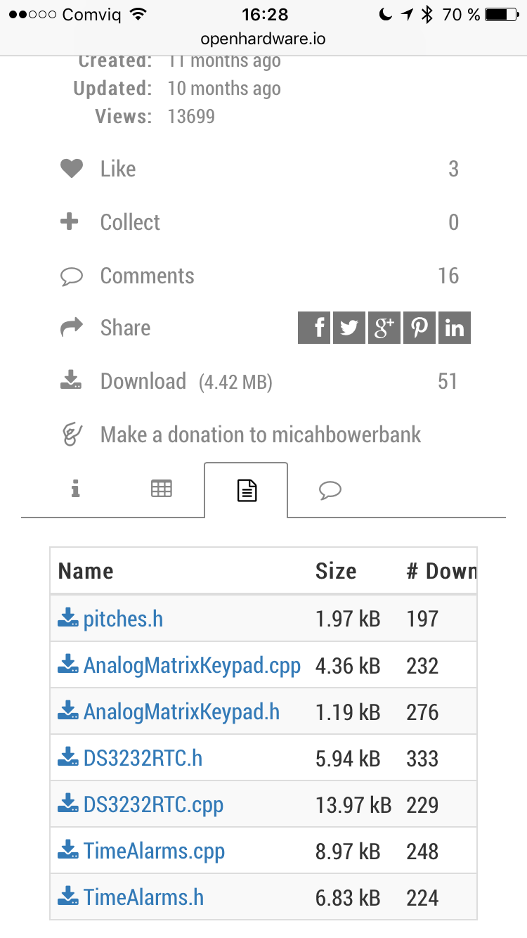
I can't find my final code file, but I did find an older version (incomplete) called ClockRebuild.ino and I uploaded it to the project.
Hopefully that helps
One day I'll come back and truly finish this project, life just keeps getting in the way
-
I am just curious why you did your switch board the way you did? You can do a similar style switch setup using all the same value resistors. Then you don't have to buy so many different resistor values. Something like this:
In this approach, whichever button you press, the resistor values, being in series, add up giving you a different voltage on your analog pin. With your approach, you use different resistor values on each switch which gives you your different voltage. My approach is only slightly different than yours. I am just wondering if there is an advantage one way or another.
@dbemowsk said in 💬 Smart Alarm Clock:
In this approach, whichever button you press, the resistor values, being in series, add up giving you a different voltage on your analog pin. With your approach, you use different resistor values on each switch which gives you your different voltage. My approach is only slightly different than yours. I am just wondering if there is an advantage one way or another.
I guess it is useful in the case when user pushes more than one button ?
-
@dbemowsk said in 💬 Smart Alarm Clock:
In this approach, whichever button you press, the resistor values, being in series, add up giving you a different voltage on your analog pin. With your approach, you use different resistor values on each switch which gives you your different voltage. My approach is only slightly different than yours. I am just wondering if there is an advantage one way or another.
I guess it is useful in the case when user pushes more than one button ?
@Nca78
exactly correct.I originally went with the same resistor value so that it was easy. But then when I thought about how many button combinations I wanted (thinking about a real clock where you hold down the alarm set button then press the hour button) I went with different values.
My implementation still isn't perfect, since I'm a bloody amateur... lol. I think 1 or 2 of the combinations I never got working.
But for the most part it accomplished what I wanted... provided many buttons and combinations on a single input pin, since I was quickly running out of them
-
I found a library online.... #include <AnalogMatrixKeypad.h>
I made some modifications (although I can't quite remember what they were), I think about the number of buttons, or combinations, or target values.
But generally the library provided the 1 wire, resistor ladder and debouncing functionality I needed
@micah Picking resistor values based on the number of switches you have shouldn't be too terribly difficult. You ar just creating a voltage divider circuit. When pushing multiple buttons, you just have to look at the resistor values for the buttons you have and calculate out the parallel resistance. Then you just have to figure out the analog value for any key combinations you want to use and create IF or Switch/Case statements to perform your logic.
-
So, I didn't look the sketch over for this, but I am planning on building one of these and I have some questions. Does this show in 12 hour or 24 hour format? If it is 12 hour, how do you indicate AM or PM? Also, do you have a way of indicating that alarms are set? I may add some LEDs for these features.
-
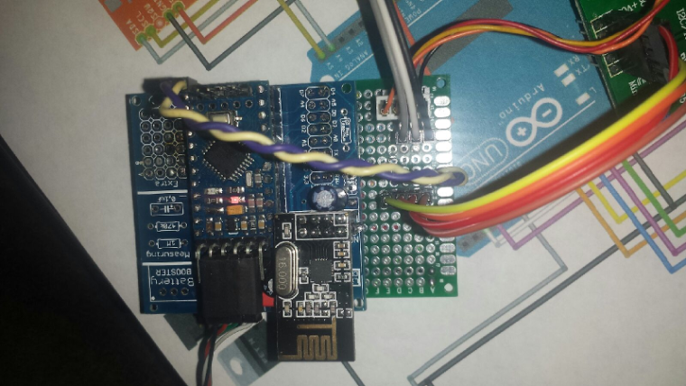
Here is my start on this. No speaker yet and I haven't added the LEDs for AM/PM and alarms, but that will come.
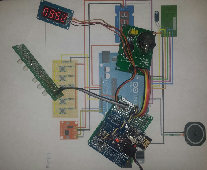
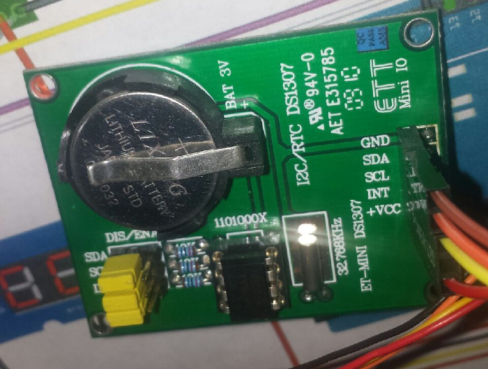
I will need to make a bunch of modifications to the sketch. Mainly because I am using a different RTC module (DS1307). It is one that I have had laying around in my parts bin for years. I get a bunch of compile errors when I try to include the RTC library for this module.
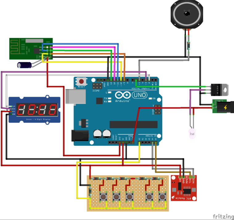
Here is the board layout so far.
Hello! It looks like you're interested in this conversation, but you don't have an account yet.
Getting fed up of having to scroll through the same posts each visit? When you register for an account, you'll always come back to exactly where you were before, and choose to be notified of new replies (either via email, or push notification). You'll also be able to save bookmarks and upvote posts to show your appreciation to other community members.
With your input, this post could be even better 💗
Register Login