Skip to content
  • MySensors
  • OpenHardware.io
  • Categories
  • Recent
  • Tags
  • Popular
Skins
  • Light
  • Brite
  • Cerulean
  • Cosmo
  • Flatly
  • Journal
  • Litera
  • Lumen
  • Lux
  • Materia
  • Minty
  • Morph
  • Pulse
  • Sandstone
  • Simplex
  • Sketchy
  • Spacelab
  • United
  • Yeti
  • Zephyr
  • Dark
  • Cyborg
  • Darkly
  • Quartz
  • Slate
  • Solar
  • Superhero
  • Vapor

  • Default (No Skin)
  • No Skin
Collapse
Brand Logo
  1. Home
  2. OpenHardware.io
  3. 💬 Smart Alarm Clock

💬 Smart Alarm Clock

Scheduled Pinned Locked Moved OpenHardware.io
alarmled ring lightspeakerdomoticzmysensorsclock
37 Posts 10 Posters 9.8k Views 12 Watching
  • Oldest to Newest
  • Newest to Oldest
  • Most Votes
Reply
  • Reply as topic
Log in to reply
This topic has been deleted. Only users with topic management privileges can see it.
  • N Offline
    N Offline
    Newzwaver
    wrote on last edited by
    #15

    Hi Can someone point me in the direction of the Ardunio code for this project? I have everything built and can get any code to work with the liquid crystal lib?

    mfalkviddM 1 Reply Last reply
    0
    • N Newzwaver

      Hi Can someone point me in the direction of the Ardunio code for this project? I have everything built and can get any code to work with the liquid crystal lib?

      mfalkviddM Online
      mfalkviddM Online
      mfalkvidd
      Mod
      wrote on last edited by
      #16

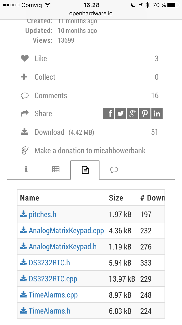
      @Newzwaver are the files in the sources tab insufficient? If so, could you clarify what is missing?

      1 Reply Last reply
      0
      • N Offline
        N Offline
        Newzwaver
        wrote on last edited by
        #17

        thanks for the reply and I might be missing it but the Arduino file is not posted under the code tab.

        mfalkviddM 1 Reply Last reply
        0
        • N Newzwaver

          thanks for the reply and I might be missing it but the Arduino file is not posted under the code tab.

          mfalkviddM Online
          mfalkviddM Online
          mfalkvidd
          Mod
          wrote on last edited by mfalkvidd
          #18

          @Newzwaver could you be a bit more specific? Which file is missing?
          0_1507127389644_IMG_5952.PNG

          There should be some file ending in .ino? So that's what is missing?

          1 Reply Last reply
          0
          • N Offline
            N Offline
            Newzwaver
            wrote on last edited by
            #19

            Yes the file ending in .ino is missing as you can see by your post above.

            1 Reply Last reply
            1
            • mfalkviddM Online
              mfalkviddM Online
              mfalkvidd
              Mod
              wrote on last edited by
              #20

              Thanks. Hopefully micahbowerbank kan reply.

              1 Reply Last reply
              0
              • N Offline
                N Offline
                Newzwaver
                wrote on last edited by
                #21

                SO does anyone have any code for this project? I need the arduino code. Thanks in advance, excellent project btw.

                1 Reply Last reply
                0
                • micahM Offline
                  micahM Offline
                  micah
                  wrote on last edited by
                  #22

                  Hey everyone.

                  Sorry, had a computer crash and file loss issue a few months ago.

                  I can't find my final code file, but I did find an older version (incomplete) called ClockRebuild.ino and I uploaded it to the project.

                  Hopefully that helps

                  One day I'll come back and truly finish this project, life just keeps getting in the way

                  1 Reply Last reply
                  1
                  • N Offline
                    N Offline
                    Newzwaver
                    wrote on last edited by
                    #23

                    Thanks for the arduino code, i will give it a shot.

                    1 Reply Last reply
                    0
                    • dbemowskD Offline
                      dbemowskD Offline
                      dbemowsk
                      wrote on last edited by
                      #24

                      I am just curious why you did your switch board the way you did? You can do a similar style switch setup using all the same value resistors. Then you don't have to buy so many different resistor values. Something like this:
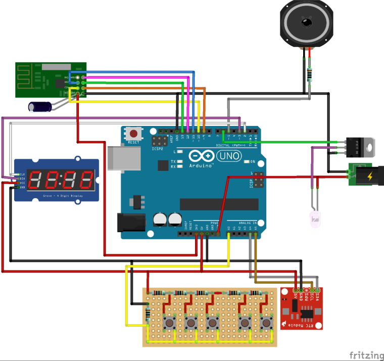
                      0_1508986754912_upload-8f7eb5ee-6fac-4bb8-8ef7-c5a3c6f82e0c

                      In this approach, whichever button you press, the resistor values, being in series, add up giving you a different voltage on your analog pin. With your approach, you use different resistor values on each switch which gives you your different voltage. My approach is only slightly different than yours. I am just wondering if there is an advantage one way or another.

                      Vera Plus running UI7 with MySensors, Sonoffs and 1-Wire devices
                      Visit my website for more Bits, Bytes and Ramblings from me: http://dan.bemowski.info/

                      Nca78N 1 Reply Last reply
                      2
                      • dbemowskD dbemowsk

                        I am just curious why you did your switch board the way you did? You can do a similar style switch setup using all the same value resistors. Then you don't have to buy so many different resistor values. Something like this:
                        0_1508986754912_upload-8f7eb5ee-6fac-4bb8-8ef7-c5a3c6f82e0c

                        In this approach, whichever button you press, the resistor values, being in series, add up giving you a different voltage on your analog pin. With your approach, you use different resistor values on each switch which gives you your different voltage. My approach is only slightly different than yours. I am just wondering if there is an advantage one way or another.

                        Nca78N Offline
                        Nca78N Offline
                        Nca78
                        Hardware Contributor
                        wrote on last edited by
                        #25

                        @dbemowsk said in 💬 Smart Alarm Clock:

                        In this approach, whichever button you press, the resistor values, being in series, add up giving you a different voltage on your analog pin. With your approach, you use different resistor values on each switch which gives you your different voltage. My approach is only slightly different than yours. I am just wondering if there is an advantage one way or another.

                        I guess it is useful in the case when user pushes more than one button ?

                        dbemowskD micahM 2 Replies Last reply
                        0
                        • Nca78N Nca78

                          @dbemowsk said in 💬 Smart Alarm Clock:

                          In this approach, whichever button you press, the resistor values, being in series, add up giving you a different voltage on your analog pin. With your approach, you use different resistor values on each switch which gives you your different voltage. My approach is only slightly different than yours. I am just wondering if there is an advantage one way or another.

                          I guess it is useful in the case when user pushes more than one button ?

                          dbemowskD Offline
                          dbemowskD Offline
                          dbemowsk
                          wrote on last edited by
                          #26

                          @Nca78 said in 💬 Smart Alarm Clock:

                          I guess it is useful in the case when user pushes more than one button ?

                          I hadn't thought about that, but you are right. In my example, you couldn't press more than one button.

                          Vera Plus running UI7 with MySensors, Sonoffs and 1-Wire devices
                          Visit my website for more Bits, Bytes and Ramblings from me: http://dan.bemowski.info/

                          1 Reply Last reply
                          0
                          • Nca78N Nca78

                            @dbemowsk said in 💬 Smart Alarm Clock:

                            In this approach, whichever button you press, the resistor values, being in series, add up giving you a different voltage on your analog pin. With your approach, you use different resistor values on each switch which gives you your different voltage. My approach is only slightly different than yours. I am just wondering if there is an advantage one way or another.

                            I guess it is useful in the case when user pushes more than one button ?

                            micahM Offline
                            micahM Offline
                            micah
                            wrote on last edited by
                            #27

                            @Nca78
                            exactly correct.

                            I originally went with the same resistor value so that it was easy. But then when I thought about how many button combinations I wanted (thinking about a real clock where you hold down the alarm set button then press the hour button) I went with different values.

                            My implementation still isn't perfect, since I'm a bloody amateur... lol. I think 1 or 2 of the combinations I never got working.

                            But for the most part it accomplished what I wanted... provided many buttons and combinations on a single input pin, since I was quickly running out of them

                            1 Reply Last reply
                            0
                            • micahM Offline
                              micahM Offline
                              micah
                              wrote on last edited by
                              #28

                              I found a library online.... #include <AnalogMatrixKeypad.h>

                              I made some modifications (although I can't quite remember what they were), I think about the number of buttons, or combinations, or target values.

                              But generally the library provided the 1 wire, resistor ladder and debouncing functionality I needed

                              dbemowskD 1 Reply Last reply
                              0
                              • micahM Offline
                                micahM Offline
                                micah
                                wrote on last edited by
                                #29

                                I often wish our fancy mysensor nRF chips only used 1 arduino wire :(

                                1 Reply Last reply
                                0
                                • micahM micah

                                  I found a library online.... #include <AnalogMatrixKeypad.h>

                                  I made some modifications (although I can't quite remember what they were), I think about the number of buttons, or combinations, or target values.

                                  But generally the library provided the 1 wire, resistor ladder and debouncing functionality I needed

                                  dbemowskD Offline
                                  dbemowskD Offline
                                  dbemowsk
                                  wrote on last edited by
                                  #30

                                  @micah Picking resistor values based on the number of switches you have shouldn't be too terribly difficult. You ar just creating a voltage divider circuit. When pushing multiple buttons, you just have to look at the resistor values for the buttons you have and calculate out the parallel resistance. Then you just have to figure out the analog value for any key combinations you want to use and create IF or Switch/Case statements to perform your logic.

                                  Vera Plus running UI7 with MySensors, Sonoffs and 1-Wire devices
                                  Visit my website for more Bits, Bytes and Ramblings from me: http://dan.bemowski.info/

                                  1 Reply Last reply
                                  0
                                  • dbemowskD Offline
                                    dbemowskD Offline
                                    dbemowsk
                                    wrote on last edited by
                                    #31

                                    So, I didn't look the sketch over for this, but I am planning on building one of these and I have some questions. Does this show in 12 hour or 24 hour format? If it is 12 hour, how do you indicate AM or PM? Also, do you have a way of indicating that alarms are set? I may add some LEDs for these features.

                                    Vera Plus running UI7 with MySensors, Sonoffs and 1-Wire devices
                                    Visit my website for more Bits, Bytes and Ramblings from me: http://dan.bemowski.info/

                                    micahM 1 Reply Last reply
                                    0
                                    • dbemowskD Offline
                                      dbemowskD Offline
                                      dbemowsk
                                      wrote on last edited by
                                      #32

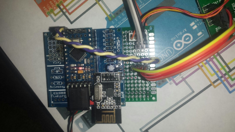
                                      Here is my start on this. No speaker yet and I haven't added the LEDs for AM/PM and alarms, but that will come.
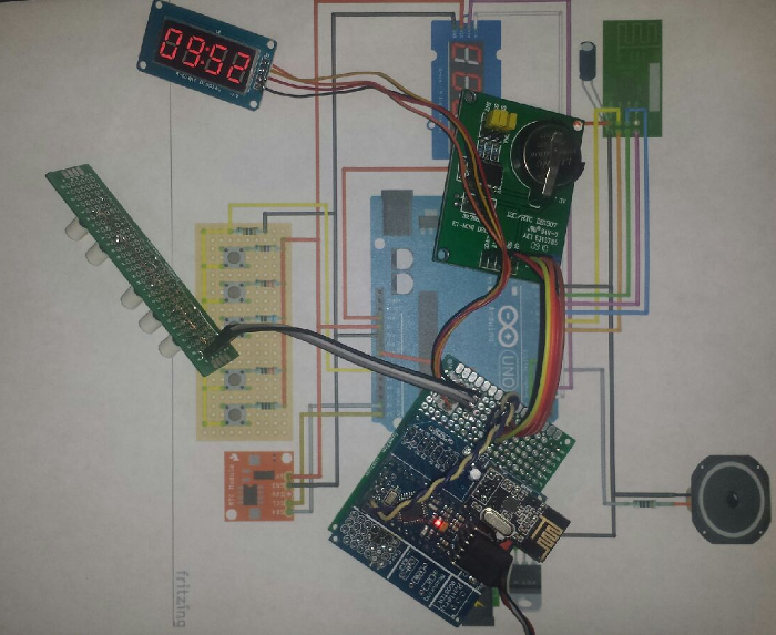
                                      0_1509333312144_upload-29d46ab7-e40a-49b9-aa1e-330beede8488

                                      I will need to make a bunch of modifications to the sketch. Mainly because I am using a different RTC module (DS1307). It is one that I have had laying around in my parts bin for years. I get a bunch of compile errors when I try to include the RTC library for this module.
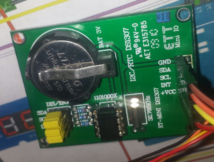
                                      0_1509333483010_upload-75b8f66d-d692-412f-9171-d0175ea0402d

                                      Here is the board layout so far.
                                      0_1509333525901_upload-7777b1c8-2200-4300-aae8-c0a94786b7c8

                                      Vera Plus running UI7 with MySensors, Sonoffs and 1-Wire devices
                                      Visit my website for more Bits, Bytes and Ramblings from me: http://dan.bemowski.info/

                                      1 Reply Last reply
                                      0
                                      • dbemowskD dbemowsk

                                        So, I didn't look the sketch over for this, but I am planning on building one of these and I have some questions. Does this show in 12 hour or 24 hour format? If it is 12 hour, how do you indicate AM or PM? Also, do you have a way of indicating that alarms are set? I may add some LEDs for these features.

                                        micahM Offline
                                        micahM Offline
                                        micah
                                        wrote on last edited by
                                        #33

                                        @dbemowsk
                                        To use a 24 hour clock switch the following bool

                                        bool Screen_HourFormat24 = false;
                                        

                                        I think I used the colon to signify that an alarm was set, I think I flashed it on and off. in the Update_Screen method

                                           if ((Alarm1_Enabled) && (!Keys_ShowAlarmOnScreen)){
                                              if(Screen_ClockPoint)ledScreen.point(POINT_ON);
                                              else ledScreen.point(POINT_OFF);
                                            } else
                                              ledScreen.point(POINT_ON);
                                        
                                        dbemowskD 1 Reply Last reply
                                        0
                                        • micahM micah

                                          @dbemowsk
                                          To use a 24 hour clock switch the following bool

                                          bool Screen_HourFormat24 = false;
                                          

                                          I think I used the colon to signify that an alarm was set, I think I flashed it on and off. in the Update_Screen method

                                             if ((Alarm1_Enabled) && (!Keys_ShowAlarmOnScreen)){
                                                if(Screen_ClockPoint)ledScreen.point(POINT_ON);
                                                else ledScreen.point(POINT_OFF);
                                              } else
                                                ledScreen.point(POINT_ON);
                                          
                                          dbemowskD Offline
                                          dbemowskD Offline
                                          dbemowsk
                                          wrote on last edited by
                                          #34

                                          @micah said in 💬 Smart Alarm Clock:

                                          To use a 24 hour clock switch the following bool

                                          I wasn't necessarily saying that I wanted to switch to 24hr format. I was wondering if you had a way of indicating AM and PM when in 12 hour format.

                                          @micah said in 💬 Smart Alarm Clock:

                                          I think I used the colon to signify that an alarm was set, I think I flashed it on and off. in the Update_Screen method

                                          I see, so when it is blinking there is an alarm and when it is on solid there is not. I may add a different alarm indicator..

                                          One other question on this. I see you have 5 buttons on your switch panel. What were your planned uses of those 5 buttons? I didn't see anything documented on that.

                                          Vera Plus running UI7 with MySensors, Sonoffs and 1-Wire devices
                                          Visit my website for more Bits, Bytes and Ramblings from me: http://dan.bemowski.info/

                                          1 Reply Last reply
                                          0
                                          Reply
                                          • Reply as topic
                                          Log in to reply
                                          • Oldest to Newest
                                          • Newest to Oldest
                                          • Most Votes


                                          15

                                          Online

                                          11.7k

                                          Users

                                          11.2k

                                          Topics

                                          113.1k

                                          Posts


                                          Copyright 2025 TBD   |   Forum Guidelines   |   Privacy Policy   |   Terms of Service
                                          • Login

                                          • Don't have an account? Register

                                          • Login or register to search.
                                          • First post
                                            Last post
                                          0
                                          • MySensors
                                          • OpenHardware.io
                                          • Categories
                                          • Recent
                                          • Tags
                                          • Popular