CNC PCB milling


  • @andrew
    1000rpm for the spindle seems very slow,is that number correct?


  • @rmtucker it is not 1000rpm, but the pwm control for the whole spindle speed range. see the details in the official document.
    once you use the spindle speed with the value of $30 or above, then the controller will drive the spindle with continuous voltage, without pwm, so it will use its maximum rpm.
    compared to bigger cncs with bigger spindles (e.g. what you can see from @executivul's video above) , 2418's is not that fast (in rpm), on the other hand it should not be "very slow". can you show a video on that?


  • @andrew
    I see.
    So what would be your best guess at your actual spindle rpm when cutting under your feed/depth of cut examples given above.?


  • Hero Member

    @andrew said in CNC PCB milling:

    I put the CNC 2418 assembly guide to my share, for ones it is interesting.

    Yes, those are exactly the same instructions I received with my kit too.


  • Hero Member

    @andrew
    I tried connecting to the Woodpecker board using the Arduino serial terminal at 115200 baud. It greets me by saying:

    Grbl 0.9j ['$' for help]
    

    However, if I send it $ I get no response. If I send it $$, I get no response either.

    Is this normal?

    How do I send it $$ and get it to respond?


  • @neverdie no, that is not normal, but this is most probably just a communication issue. which software is used for the terminal connection? try to change the cr/lf settings, or the flow control options.


  • @rmtucker I did not measure the max rpm for the given spindle, but I use it on "max" (so spindle setting is 1000) for the given jobs.


  • Hero Member

    Ah, nevermind. I changed the terminal to send it a carriage return, and now it works. Here is the output from asking it $ and $$:

    
    Grbl 0.9j ['$' for help]
    $$ (view Grbl settings)
    $# (view # parameters)
    $G (view parser state)
    $I (view build info)
    $N (view startup blocks)
    $x=value (save Grbl setting)
    $Nx=line (save startup block)
    $C (check gcode mode)
    $X (kill alarm lock)
    $H (run homing cycle)
    ~ (cycle start)
    ! (feed hold)
    ? (current status)
    ctrl-x (reset Grbl)
    ok
    $0=10 (step pulse, usec)
    $1=25 (step idle delay, msec)
    $2=0 (step port invert mask:00000000)
    $3=5 (dir port invert mask:00000101)
    $4=0 (step enable invert, bool)
    $5=0 (limit pins invert, bool)
    $6=0 (probe pin invert, bool)
    $10=3 (status report mask:00000011)
    $11=0.010 (junction deviation, mm)
    $12=0.002 (arc tolerance, mm)
    $13=0 (report inches, bool)
    $20=0 (soft limits, bool)
    $21=0 (hard limits, bool)
    $22=0 (homing cycle, bool)
    $23=0 (homing dir invert mask:00000000)
    $24=25.000 (homing feed, mm/min)
    $25=500.000 (homing seek, mm/min)
    $26=250 (homing debounce, msec)
    $27=1.000 (homing pull-off, mm)
    $100=800.000 (x, step/mm)
    $101=800.000 (y, step/mm)
    $102=800.000 (z, step/mm)
    $110=5000.000 (x max rate, mm/min)
    $111=5000.000 (y max rate, mm/min)
    $112=800.000 (z max rate, mm/min)
    $120=10.000 (x accel, mm/sec^2)
    $121=10.000 (y accel, mm/sec^2)
    $122=10.000 (z accel, mm/sec^2)
    $130=200.000 (x max travel, mm)
    $131=200.000 (y max travel, mm)
    $132=200.000 (z max travel, mm)
    ok
    

  • Hero Member

    Here's the current build status:
    0_1513549544809_build_status_1.jpg
    I'm guessing I'm something more than half-way done.


  • Hero Member

    @andrew said in CNC PCB milling:

    the ER11 should be warmed up

    how exactly? Heat gun?

    I've put the motor assembly in the freezer....


  • Hero Member

    I'll let it freeze overnight and then try it in the morning.


  • Hardware Contributor

    @neverdie said in CNC PCB milling:

    freeze

    Why do you want to freeze the motor? 👀


  • Mod

    @sundberg84 see andrew's earlier post.

    Freezing the motor axis makes it a bit smaller.


  • @sundberg84 And heating up the other part makes it expand and get bigger allowing the two to fit together easier. Has to do with tight tolerances.


  • Hero Member

    @andrew
    Since I probably have only one shot at this, how hot should I heat up the ER11 before trying to fit it onto the frozen spindle? Should it be burning hot, or is luke-warm enough?


  • @neverdie unfortunately, as I mentioned, I don't have ER11 (yet), and I just read articles and vendor suggestions on the installation method, so I cannot provide experience based suggestions to that. as far as I remember nor concrete temperature was mentioned, so I would say you should not "overheat" it.


  • Hero Member

    @andrew said in CNC PCB milling:

    @neverdie unfortunately, as I mentioned, I don't have ER11 (yet), and I just read articles and vendor suggestions on the installation method, so I cannot provide experience based suggestions to that. as far as I remember nor concrete temperature was mentioned, so I would say you should not "overheat" it.

    I slipped it on, no problem at all. After freezing the motor overnight, what I did was heat the ER11 with my wife's crafting hot air gun. I held it with an insulated glove as I warmed it up. When it started to become uncomfortable to hold with even the insulated glove, I slipped it on without any resistance.

    Hopefully this info will help you when you receive yours.


  • @neverdie 🙂 nice, so your wife saved the project :)))
    be patient and do not power the spindle for couple of hours, while it is cold, as it could be wet inside which could cause shorts and other issues.


  • Hero Member

    I seem to be finished with the mechanical assembly:
    0_1513629200578_mechanicals_done.jpg
    However, these washers came with the kit, and I'm not sure what they're for:
    0_1513629228821_washers.jpg
    Anyone know? Are they for mounting the woodpecker board to the frame?

    Next I need to do the firmware upgrade and then wire things up.


  • @neverdie yes, it is for "isolating" the pcb from the frame.


  • @neverdie said in CNC PCB milling:

    ER11

    FYI - Was reading on another forum where the user was going to replace the ER11 with a larger version so he could use 8mm bits (fairly standard metric size for wood routing bits, but incredibly strong)...
    Somebody pointed out to the guy that there are collets available for the ER11 specifically for 8mm shafted toolbits...
    https://www.sorotec.de/shop/Spannzange-ER-11---8-00mm-DIN-6499B-4008E-Klasse-II.html


  • @neverdie
    You have gone quiet☺
    Must be beavering away cutting pcb's?


  • Carved this on my home made cnc router recently.
    Bit off topic but good fun.
    It is about 2ft diameter and 8" thick(old millstone)
    0_1513689287536_aa2a84b0-71ec-4d46-9c2d-f2241aa2827a-image.png


  • @rmtucker
    And this for our lass
    0_1513689365865_382c70bc-e450-4cc8-89c9-f0cc3bd45522-image.png


  • Hero Member

    @rmtucker said in CNC PCB milling:

    @neverdie
    You have gone quiet☺
    Must be beavering away cutting pcb's?

    No, I've simply misplaced my Dragon AVR programmer for the firmware upgrade, so I need to hunt it down.


  • Hero Member

    Anyway, once I do get the firmware upgraded and it wired up, what's the best way to start testing it? Do I need to learn GRBL as execuval seems to imply, or are there some simple tests I can run? I imagine some kind of calibration would be the need step, but I haven't read that far ahead because there's nothing to read (well, haven't googled it out yet either).


  • @neverdie
    Stick some g-code in and press cycle start😁


  • Hero Member

    @zboblamont said in CNC PCB milling:

    was going to replace the ER11 with a larger version

    Given how it's installed, I don't see how you can get it off. I would assume it's permanent.


  • @neverdie From memory the guy got it off with a hub-puller, and a persuader, but the point I was trying to make was that there is a collet assembly for the ER11which takes 8mm...


  • @neverdie said in CNC PCB milling:

    Anyway, once I do get the firmware upgraded and it wired up, what's the best way to start testing it? Do I need to learn GRBL as execuval seems to imply, or are there some simple tests I can run? I imagine some kind of calibration would be the need step, but I haven't read that far ahead because there's nothing to read (well, haven't googled it out yet either).

    First watch the video (now I can't get it out of my head 🙇‍♂️ )
    The Ting Tings - That's Not My Name (lyrics) – 05:05
    — GrubbyTubby

    Then, after you update to grbl 0.9j go to chilipeppr.com/grbl, download the SPJS, start it and start playing.


  • Hero Member

    I hope these heatsinks that came with the kit don't short things out. Seems rather dicey.
    0_1513705183502_heatsinks.jpg

    In any case, until I can find my Dragon, I'm going to limp along with GRBL 0.9j so I can finish up the build. I'll upgrade later after I find it.


  • @neverdie the er-11 should be permanent. this spindle is not powerful enough to handle bigger tools and to mill harder materials.

    you can start with grbl 0.9j, but it is worth to upgrade to 1.1f.
    to the fw upgrade you can use a simple arduino as ISP programmer as well if you do not find your dragon.

    with chilipeppr (in case of grbl 0.9j go for http://chilipeppr.com/grbl , for 1.1.f go for http://chilipeppr.com/jpadie) you can quickly run its default logo engraving path for testing / demo purposes.


  • Hero Member

    Done! Jack was certainly, uh, generous with the length of the wiring. I provisionally tacked it out of the way with the zip ties provided. I'll secure it better after I'm sure it's all working.
    0_1513707091383_wiring.jpg


  • @neverdie for the cable issue I ordered this cable organizer spiral, although not yet installed it 🙂


  • Hero Member

    @andrew said in CNC PCB milling:

    with chilipeppr (in case of grbl 0.9j go for http://chilipeppr.com/grbl , for 1.1.f go for http://chilipeppr.com/jpadie) you can quickly run its default logo engraving path for testing / demo purposes.

    Thanks! That provided exactly what I was looking for. I ran the demo with no etching bit installed, and at first both X and Y seemed to be working, but the adapter coupling eventually loosened on both of them to the point where there was no longer X and Y movement. I've re-tightened tem, and it's working again. I hope it lasts.

    Not sure where I should go next from here though.


  • @neverdie said in CNC PCB milling:

    @andrew said in CNC PCB milling:

    with chilipeppr (in case of grbl 0.9j go for http://chilipeppr.com/grbl , for 1.1.f go for http://chilipeppr.com/jpadie) you can quickly run its default logo engraving path for testing / demo purposes.

    Thanks! That provided exactly what I was looking for. I ran the demo with no etching bit installed, and at first both X and Y seemed to be working, but the adapter coupling eventually loosened on both of them to the point where there was no longer X and Y movement. I've re-tightened tem, and it's working again. I hope it lasts.

    Not sure where I should go next from here though.

    so, as this machine does not have limit switches installed, it is your responsibility to move the gantry to a position, from where you would like to start the job and which provides enough space for each direction movement. usually you have to set a relative zero at the given starting point.

    what is next? did you adjusted the stepper drivers? if not, then do it (I shared the link above). this is necessary to be sure, that the steppers will be powered with enough current (so they will be powerful enough for the given speed related movement and to provide enough force) or will not be overdriven.

    then, I would say try to engrave the chilipeppr logo to a soft material first, have some experience with the cnc.
    then, as I mentioned, discover the flatcam tool and try to create an isolation routing job for a test pcb.
    I already mentioned my confirmed settings for the given jobs (edge / hole milling, isolation routing).
    you should sacrifice some boards for your experience 🙂

    also, try to find your ideal g code sender tool by trying multiple ones.


  • Hero Member

    I don't see any plugs on the woodpecker board that are designated for connecting to a touch plate. So, I guess it's configured using the woodpecker header pins? How is that best set up?

    By the way, after re-tightening the set-screws on the adapters used to connect the step-motors to the screw rods, they seem to be holding now and not slipping loose. I take it back, one of them just came loose again. 😞


  • Hero Member

    @neverdie said in CNC PCB milling:

    one of them just came loose again

    And now the other one did too. Is anyone using a threadlocker on the set screws to keep this from happening?

    I think I'll put on some locktite and let it dry overnight and then see if it still happens tomorrow. I'll start with just the threaded rods.

    Anyhow, the good news is that the heat sinks plainly did not short out the GRBL controller boards. I guess the adhesive must act as an electrical insulator.


  • Hero Member

    Thinking about it now, an alternative might be to grind one side of the threaded rod flat in the region where it fits into the adapter. That would match the concept of the motor rotor, where that has already been done.

    Ideally I would notch it in just the region where the set screw makes contact. I suppose I could do that with a Dremel.

    Investigating now, I see that the adapter came loose on the motor rotor also. So, I think locktite will be a must.

    http://www.loctiteproducts.com/tds/T_LKR_BLUE_tds.pdf

    Looking at the datasheet, it takes 24 hours to cure.


  • Hero Member

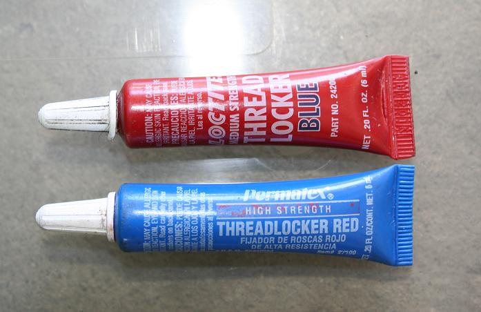
    Well, humbug! I'm all out. Maybe tomorrow I'll buy the red threadlocker, which is even stronger.


  • Hero Member

    @rmtucker Which g-code sender is it that you like best?


  • @neverdie, or anyone else that can answer this with some logic, just because the topic came up. Why does Loctite red come in a blue container and loctite blue come in a red container?
    0_1513751591321_cf4dc6b4-34f3-453c-a624-05994fbca118-image.png


  • Mod

    @dbemowsk said in CNC PCB milling:

    Why does Loctite red come in a blue container and loctite blue come in a red container?

    Made in China?


  • Hero Member

    Probably historical reasons.


  • @yveaux LOL


  • Hero Member

    Probably a committee decision. Half liked red, and the other half liked blue. They were deadlocked, and this was their compromise decision. 😆


  • @neverdie for the touch sensing you should use A5 connector from the headers, connecting it to the actual tool (bit), then a gnd (header's bottom row) connecting to the pcb's surface.

    for the tool connection I use crocodile clamps.

    screws: you did not fasten them enough. at the beginning I also missed some endpoints, but since I put the cnc together, I had no issue with any of my screws.


  • @andrew for first go for a single touch probing instead of a whole autoleveling session.
    just for testing purposes, start the touch probing from a higher position and touch the gnd wire directly to the spindle's tool to see whether it stops or not. if not, you should stop it manually from the gui, otherwise it could break the tool.
    if everything works well (so you proved that you connections to the pins and the belonging settings are ok), then you can run the simple touch probes or the autoleveling as well.


  • Hardware Contributor

    @neverdie said in CNC PCB milling:

    Is anyone using a threadlocker on the set screws to keep this from happening?

    For one that will probably buy the same CNC could you document how you solve this with a picture?


  • @neverdie said in CNC PCB milling:

    @rmtucker Which g-code sender is it that you like best?

    I am not using a g-code sender,i am using mach3.
    But i have just started playing with grbl and bCNC seems to do most things.


  • @neverdie one more think I forgot to mention: after I assembled the cnc, I used a little wd40 across each axis and moved each from one end to another. it helped for smooth and "barrier-free" movements.


  • Hero Member

    @andrew said in CNC PCB milling:

    you should use A5 connector

    Does using A5 somehow automagically just work, or does it require additional software configuration?


  • Hero Member

    @sundberg84 said in CNC PCB milling:

    @neverdie said in CNC PCB milling:

    Is anyone using a threadlocker on the set screws to keep this from happening?

    For one that will probably buy the same CNC could you document how you solve this with a picture?

    OK, here is what I'm doing in pictures. I'm applying blue 242 Loctite:
    0_1513780511391_loctite.jpg
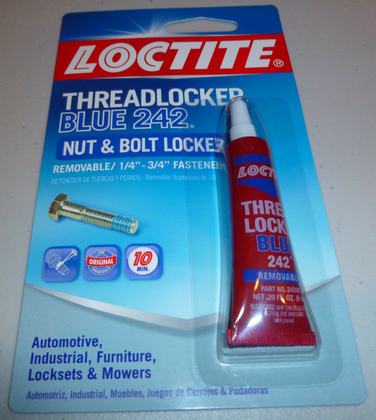
    to the threads of the 4 set screws on the coupler:
    0_1513780537893_coupler.jpg
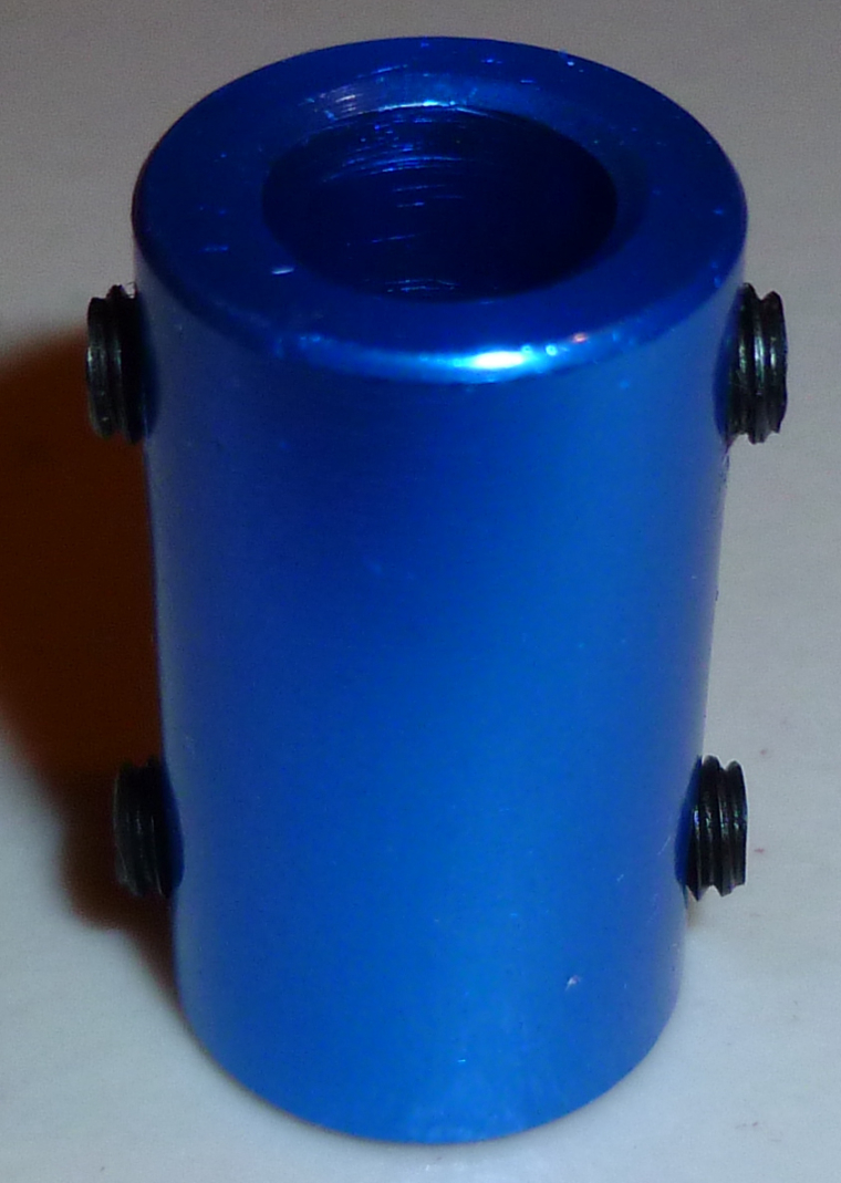
    That should keep them from loosening up after they are screwed into position. Note, you have at most 10 minutes of working time before it sets.


  • Hero Member

    I applied it to the motor set screws first and let it set:
    0_1513782061856_magnet.jpg
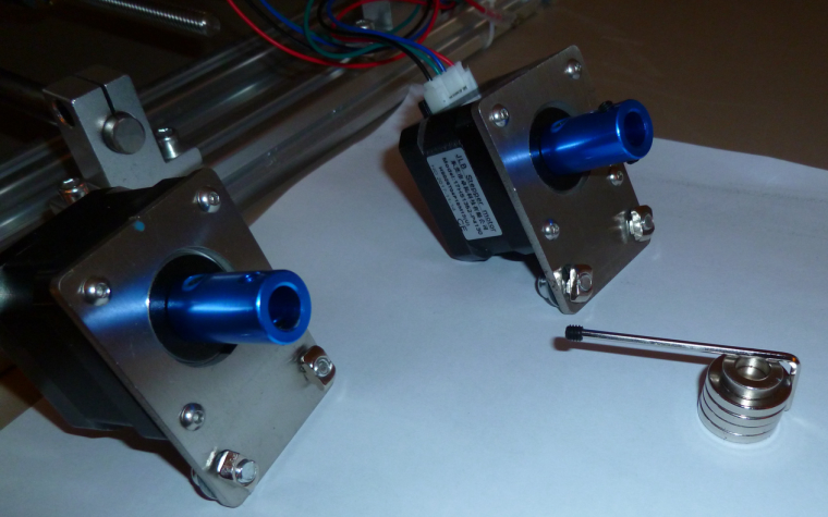
    Note: I used rare earth magnets to help secure the set screw to the allen wrench. That insures that the set screw doesn't drop off and disappear somewhere on the floor. Works great.

    The couplers are made from anodized aluminum, so I'm not sure how well the loctite will work on them. However, I think it will still work, as the set screws themselves are steel.


  • Hero Member

    I found an intro to bCNC:
    Shapeoko 3 bCNC Beginner Tutorial – 08:40
    — BluegrassRC

    It looks easy and intuitive, so I'll probably go with that.

    As usual, it's the software that has the best tutorial that wins.


  • @neverdie I used to use nail varnish on threads as it was just as effective, even though it annoyed the partner whose nail varnish it was. It is not the bond between the metals which is that important, it is adding resistance between the threads to prevent unscrewing, were it to completely bond, you would shear the bolt before it was removed, which is a whole lot of trouble....


  • Hero Member

    @zboblamont said in CNC PCB milling:

    @neverdie I used to use nail varnish on threads as it was just as effective, even though it annoyed the partner whose nail varnish it was. It is not the bond between the metals which is that important, it is adding resistance between the threads to prevent unscrewing, were it to completely bond, you would shear the bolt before it was removed, which is a whole lot of trouble....

    Does nail varnish cure anaerobically in the presence of metal ions? That seems to be much of the theory behind thread lockers.

    I thought nail varnish cured by evaporation.

    In any case, I wiped off the excess loctite, because it might never dry (or, at least, take a long while to do so).

    I think the loctite is likely to work, since Andrew had success without anything but torquing it down hard. On the other hand, maybe his is threaded differently than what came in my kit.


  • @neverdie said in CNC PCB milling:

    @andrew said in CNC PCB milling:

    you should use A5 connector

    Does using A5 somehow automagically just work, or does it require additional software configuration?

    it should work by default


  • @neverdie Torquing down correctly normally prevents threads unwinding, but have seen bolts come loose with vibration on occasion. Only ever used loctite or equivalent on cylinder head bolts, particularly alloy heads, it never actually sets solid and is oil etc resistant.
    Although lacquer or plastic paints do harden, as a plastic filler between the threads, it increases contact friction, yet will shear to permit removal of the bolt when necessary. Typical threads do not fully engage metal to metal, the clearance is essential to allow the nut to be run on the bolt.
    Loctite is fine if you have it already, nail varnish works fine for me in non oily scenarios.


  • Hero Member

    I've retried it now, and so far it's not coming lose. 🙂

    I added some machine oil on the rods and screws, and that seems to have helped. Before that, there were some areas where the screw rod on the y-axis was binding, but not now.


  • Hero Member

    Are you guys running bCNC under Linux? Because installing it under Windows is proving to be challenging....


  • @neverdie yep, I've a linux vm for flatcam and bcnc.


  • @neverdie
    Linux for me too.Never used windows in years☺


  • Hero Member

    Here's the machine oil I'm using. As you can tell from the manufacturer, it's meant for sewing machines and similar:
    0_1513883937810_oil1.jpg0_1513884033669_oil2.jpg


  • Hero Member

    Well, now that I found this pulldown in Chilipeppr, I might stick with it a while longer:
    0_1513887938761_axes.png


  • Hero Member

    The strange thing is that the Chilipeppr demo seems to mill at z=0.000. So, if I were to try to etch the pattern for real, I would have to "zero" z at an actual z value of, say, z=-0.5 or something (whatever depth I wanted it to etch at).

    Is that normal?

    Anyhow, I've been through multiple trial iterations with no bit installed and with the spindle disabled, and during all that the X and Y couplers have not come loose. So, I think that the Locktite has lived up to its name and solved the problem I was having earlier. 🙂


  • @neverdie said in CNC PCB milling:

    The strange thing is that the Chilipeppr demo seems to mill at z=0.000. So, if I were to try to etch the pattern for real, I would have to "zero" z at an actual z value of, say, z=-0.5 or something (whatever depth I wanted it to etch at).

    Is that normal?

    Anyhow, I've been through multiple trial iterations with no bit installed and with the spindle disabled, and during all that the X and Y couplers have not come loose. So, I think that the Locktite has lived up to its name and solved the problem I was having earlier. 🙂

    yes, the chilipeppr demo works like this. but keep in mind, that for "real" isolation milling, the milling depth which you used during the g code generation will be calculate from the relative z zero, so in that case you really have to set z0 to the pcb surface.


  • Hero Member

    Disaster. Out of the blue, it suddenly just stopped working. Now I can't get it to spin the spindle or move in any x, y, or z direction. Gcode appears to be sent to it, and it does respond to me if I send it a '$" through the Chilipeppr console window. Just no movement whatsoever.

    I removed the heatsinks, as a possible culprit, but still no go.

    Suggestions on how to diagnose it?


  • Hero Member

    I found the problem: bad power supply brick. It is supplying no voltage at all. 😞

    The power brick that came as part of the kit says it is rated at 24v dc 5.62amp. Is that enough, or should I get something that can do more amps?


  • @neverdie oh 😞 if you have a chance to power the cnc from a variable current power supply, then check the current it drains by starting from low to higher current. if it eats lot, maybe there is a short somewhere. you could also try to open the power supply and find a fuse.
    good luck!


  • @neverdie I've a PS with the same parameters. it is enough.


  • Hero Member

    I don't have much optimism that the cheap-ass power supply that came with the kit can be repaired (well, not by me anyway).

    I ordered a 6amp one as a replacement, just to have a little more headroom:
    https://www.amazon.com/gp/product/B01AJQ9G2C/ref=oh_aui_detailpage_o01_s00?ie=UTF8&psc=1

    It may turn out to be cheap-ass also, but I can get it tomorrow, so I'm rolling the dice.

    If that burns out too, then there's this one, which looks more beefy and would be my first choice, but will take a week to receive it:
    https://www.amazon.com/gp/product/B01J19G00E/ref=oh_aui_detailpage_o00_s00?ie=UTF8&psc=1


  • Hero Member

    Dang. I cancelled the order, as I'm not sure whether its 5.5mmx2.1mm barrel jack will fit or whether a 5.5mm x2.5mm is required.

    Looks as though the barrel on the woodpeck is 2.5mm inside diameter....


  • Hero Member

    Powering it from a variable power supply, it apparently works. Here's the etching on a piece of plywood:
    0_1513906179776_logo.jpg
    I watched the current being drawn, and it appeared to always be below 1 amp. The variable power supply can supply up to 5 amps, so no problem there as far as I can see.

    The etching that it did was a bit weird: deep cuts in the inside diameter of the P's, but only faint cuts just outside. The R was barely even touched at all. The surface doesn't feel sufficiently non-flat to account for that.

    Ideas as to what's going wrong there?


  • Hero Member

    Here is a contextual photo:
    0_1513907110706_context.jpg
    The clamps are holding the board very securely.


  • Hero Member

    After thinking about it, my hypothesis is that the feedrate is too high. I have it set to 1 in ChilliPeppr. I think maybe it comes down rapidly to the programmed height, but if it meets resistance then it skips some motor steps. Since it's open loop, it doesn't know. Then it dwells at that depth until it picks up the bit and relocates. I'll try a slower feedrate and see if it makes a difference.


  • Hero Member

    Maybe the bit is too dull as well. It's one of the freebies that came with the kit.


  • Hero Member

    Also, what is the preferred way to tighten the ER11 chuck? So far, I did it just by hand, which seems to have been good enough. However, maybe a better practice is to give it a 1/4 turn further tightening using wrenches after that? How are others here approaching that?


  • @neverdie for er11 fastening you should use two wrenches.

    if you loose steps during the milling, then with the given feed rate / depth / spindle speed combination the cnc / spindle / steppers are not powerful enough.

    if you wood milling depth is not constant then:

    • the wood is not flat
    • the cnc bad is not flat
    • the cnc x axis is not horizontal

    my availability for the next couple of days will be quite limited, so I wish you good luck for experiencing the router and for the first PCBs!


  • @neverdie said in CNC PCB milling:

    Also, what is the preferred way to tighten the ER11 chuck? So far, I did it just by hand, which seems to have been good enough. However, maybe a better way is to give it a 1/4 turn further tightening using wrenches after that? How are others here approaching that?

    +1 for the wrench, mostly because of vibrations that could unscrew it. No need to pull a muscle on it as it is tapered and has big contact surface


  • @neverdie If it is anyway similar to a Router, it should have a locking pin to hold the spindle, or a second nut against which you tighten the collet. Do not overtighten, just enough to bite the shaft, otherwise you either damage the shaft or more seriously shatter the collet, it should be just enough to be a firm clamp to ensure grip, the collet will do the rest.
    Not a user of these CNCs but I would guess the same principles apply... Just my 2c...


  • Hero Member

    @andrew

    Have a Merry Christmas!

    Also, I'm not going to dwell on etching wood . It was just my first attempt at etching anything, and I thought wood might be a little softer.

    I suppose the next step is to have a go at auto-leveling on a PCB rather than perfect the machine's etching of plywood. Indeed, PCB's may turn out to be easier, as the resistance to downward motion (especially after auto-levelling) should be more uniform.


  • Hero Member

    Meh, I think I know what happened now. If the z-axis ever skips a step in downward motion--for whatever reason--then the rest of the etching is screwed from that point forward, because the higher height then becomes the new "zero" for the entire remainder of the etching since the depth control is completely open loop. So, the first spot in the sequence that isn't at proper depth would be where the error occurred, creating a persistence of the error from that point forward in the etching sequence.


  • @neverdie If the material is parallel to the cutting plane, the cut depth should be constant. Might I suggest doing same experiment using auto-level.... Wood is easier on the bits, plywood less so but still less abrasive than FR4...


  • Hero Member

    @zboblamont said in CNC PCB milling:

    Might I suggest doing same experiment using auto-level....

    Is there an auto-level that works on wood? I thought it assumed a conductive surface, like on a blank copper PCB, to facilitate the auto-leveling mapping process, so that it knows when contact is made and therefore the height at each touch point.


  • @neverdie Tinfoil?


  • @neverdie I should explain my thinking... I do not think your wood experiment made sense. You assume your sensors and the wood are parallel, this need not be true. Plywood is generally less than 0.3mm out of true, even if you could zero the 4 corners with foil or similar it would give you a plane on which to see if the original trial was misleading.


  • Hero Member

    @zboblamont said in CNC PCB milling:

    @neverdie Tinfoil?

    You get an A+ for creative thinking. I suppose extra wide foil tape might work.


  • @neverdie I was thinking kitchen foil pressed flat as possible to the block surface, whatever works...


  • Hero Member

    This is a good video for how to auto level in ChiliPeppr:
    Auto-Level a PCB in ChiliPeppr – 21:33
    — John Lauer

    So, with that as inspiration, I plan to connect the probe to A5 on the woodpecker, and the PCB surface to GND. He soldered his ground wire to the PCB, so I guess I'll do the same, at least for now.

    I'll use tape to secure the PCB to the sacrificial board underneath.


  • Hero Member

    I've confirmed that A5 and GND work correctly for the auto-leveling.

    However, Chillipeppr strangely defaults to probe a much larger area than is needed for auto-leveling, so I need to figure out how to reduce the upper and right-hand boundaries of the probing area:
    0_1513977914047_too_large.png

    Otherwise, it runs the risk of not even hitting the PCB if it gets too far out.


  • Hero Member

    Nailed it!
    0_1513979933006_just_right.png

    Well, further progress will have to wait until I can move the CNC to the garage or outdoors, so that I don't fill the house with toxic fiberglass particles (Thank you @executivul for pointing that out, and sorry I butchered your name earlier. I didn't mean to.)


  • @neverdie no problem, I got used to it since I'm using such a weird nickname, the good part is it's always free to register on any forum so all I have to remember is the pass.

    I'm really excited about wet milling, it's freezing down here and not having to have windows open for the modded vacuum cleaner it's a treat. The trick is to use a solution with higher surface tension then water, but not too thick or it will gather around the mill as a small tornado and start splashing everywhere. You can use soap, shampoo, dishwash, carwash, etc. Start at 1:1 water mix and add more water if it tends to gather around the spinning bit. It's better to pour it slowly on the board and spread with your finger (use a syringe) than to spray it as not to make foam. Also try using a clear shampoo to better see what's milling below the liquid. A piece of flat plastic, acrylic, lexan, plexiglas, whatever, doublesided taped to the wood spoilboard is a must unless you leave a large margin between the actual milling and pcb edge liquid will spill and will swell the wood. Have a roll of paper sheets nearby and a garbage bag open. Always use glasses when operating the machine. I made a "fence" out of some polycarbonate sheet to contain any eventual splashes which occur mostly when drilling through the board, normal engraving behaves and doesn't splash at all.


  • Hero Member

    Given that the goal is to get 6mil isolatioin routing, what cutting depth should I set in flatcam? 0.05mm?


  • @neverdie I have been kind of following this topic, but don't have a CNC mill, but wouldn't the thickness of the copper clad on the board be your depth?


  • Hero Member

    @dbemowsk said in CNC PCB milling:

    @neverdie I have been kind of following this topic, but don't have a CNC mill, but wouldn't the thickness of the copper clad on the board be your depth?

    Makes sense to me. Well, doing that it would be 0.01mm. But since this isn't a perfect process, it likely needs some added depth to guarantee it's removed. The effective tool width gets wider the deeper you cut, so in some sense I suppose there's that as an added constraint on how deep you can cut before it becomes more than 6 mil isolation. We could try to arrive at an answer analytically from first principles only, but I thought it might be easier to just ask what depth others who are doing this successfully are using.


  • @neverdie See what depth you need to go with that bit to get 6 mil routing, and that will be your max. I would think that would be more than 0.01mm, but I haven't seen your bit, so I don't know.


  • @neverdie you should use one depth, regardless of the trace width. for me 0.05mm worked, see my shared settings above. you should decide the isolation width, this is the main property for the given config, but you should stick for one milling depth only. if the requires isolation width is bigger than the tool width at a given depth, then it will use multiple rounds to reach the given width, but still, with one milling depth.


  • Hero Member

    I'm stuck. I converted my gerber to gcode using flatcam, and imported it into Chilipeppr:
    0_1514058048699_stuck.png
    On the one hand, it seems to have gotten the dimensioning right, as indicated by the Y1.48in and X1.43in. However, the grid that it's showing is out of sync with that. Each square on the grid is 5mm. It's as though Chilipeppr thinks the entire design fits easily inside a 5mm square, and so when I attempt to do the autoleveling, it comes out completely wrong.


  • @neverdie said in CNC PCB milling:

    I'm stuck. I converted my gerber to gcode using flatcam, and imported it into Chilipeppr:
    0_1514058048699_stuck.png
    On the one hand, it seems to have gotten the dimensioning right, as indicated by the Y1.48in and X1.43in. However, the grid that it's showing is out of sync with that. Each square on the grid is 5mm. It's as though Chilipeppr thinks the entire design fits easily inside a 5mm square, and so when I attempt to do the autoleveling, it comes out completely wrong.

    you can mark the zero point in the pcb designer tool before you export the gergbel, or in flatcam, during the post processing. if you do not define it, then maybe the given zero point could have some "offset" to the effective design. it is not problem, but it could make your life easier if your zero is e.g. at the pcb's corner.
    if you don't want to update the files, then in chilipeppr you can update the probe area to not start from 0,0 but from a given offset.


Log in to reply
 

Suggested Topics

  • 4
  • 9
  • 1
  • 9
  • 2
  • 14

0
Online

11.2k
Users

11.1k
Topics

112.5k
Posts