Skip to content
  • MySensors
  • OpenHardware.io
  • Categories
  • Recent
  • Tags
  • Popular
Skins
  • Light
  • Brite
  • Cerulean
  • Cosmo
  • Flatly
  • Journal
  • Litera
  • Lumen
  • Lux
  • Materia
  • Minty
  • Morph
  • Pulse
  • Sandstone
  • Simplex
  • Sketchy
  • Spacelab
  • United
  • Yeti
  • Zephyr
  • Dark
  • Cyborg
  • Darkly
  • Quartz
  • Slate
  • Solar
  • Superhero
  • Vapor

  • Default (No Skin)
  • No Skin
Collapse
Brand Logo
  1. Home
  2. OpenHardware.io
  3. 💬 NRF2RFM69

💬 NRF2RFM69

Scheduled Pinned Locked Moved OpenHardware.io
rfm69adapterconverternrf24l01
113 Posts 29 Posters 30.4k Views 24 Watching
  • Oldest to Newest
  • Newest to Oldest
  • Most Votes
Reply
  • Reply as topic
Log in to reply
This topic has been deleted. Only users with topic management privileges can see it.
  • gohanG gohan

    I got them from seeed studio, no problem

    J Offline
    J Offline
    jostor
    wrote on last edited by
    #90

    @gohan But then I guess you didn't use the panel version?
    From what I can see it looks like the drill file in the panel version is missing the drill holes on the board itself. It looks like it only contains the drill holes between the cards? I am not sure, and has little experience with drill files and pcb design, but it looks like this when I open the drill file (and the profile layer, .gml-file) in gerbview in kicad:
    0_1516022887876_de7ec221-3c6f-4fba-ba8f-def608ce3788-image.png

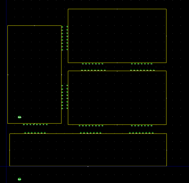
    From what I can see the drill holes on the boards itself is missing, but I guess there are others that have ordered this panel version from dirtypcbs, so I find it strange that there should be an error.

    1 Reply Last reply
    0
    • tbowmoT Offline
      tbowmoT Offline
      tbowmo
      Admin
      wrote on last edited by
      #91

      @jostor

      That sounds weird, as I haven't touched the files at dirtypcb for the last couple of years.. And I got a notification from dirtypcb the other day, that another set was successfully ordered..

      Perhaps it's a fluke in their system?

      1 Reply Last reply
      0
      • J Offline
        J Offline
        jostor
        wrote on last edited by
        #92

        @tbowmo
        OK. Then I guess the files are OK, and that the error is in dirtypcb's system. Thanks!
        But what about the drill file on your github. Why am I not seeing the drill holes on the card itself when I am opening it? Shouldn't they be a part of the drill file?

        tbowmoT 1 Reply Last reply
        0
        • J jostor

          @tbowmo
          OK. Then I guess the files are OK, and that the error is in dirtypcb's system. Thanks!
          But what about the drill file on your github. Why am I not seeing the drill holes on the card itself when I am opening it? Shouldn't they be a part of the drill file?

          tbowmoT Offline
          tbowmoT Offline
          tbowmo
          Admin
          wrote on last edited by
          #93

          @jostor

          probably.. Can't remember much of what I did 2 years ago :)

          J 1 Reply Last reply
          0
          • tbowmoT tbowmo

            @jostor

            probably.. Can't remember much of what I did 2 years ago :)

            J Offline
            J Offline
            jostor
            wrote on last edited by
            #94

            @tbowmo
            That's understandable :-)

            I received this email from dirtypcbs today:

            "Thanks for ordering!
            So here is the thing- please see attached screenshots. The only drill holes in this Gerber are the mouse bits(the pink layer, photo 001). The light green layer(photo 002) is the top solder mask layer. The problem is that no drills are specified in the solder pads or circles, which means that if we make the board exactly how the gerber is designed, all of the light green parts are solder pads and there WILL NOT be drill holes at the bottom of the solder pads, which seems wrong.
            I checked this gerber in our system, and I couldn't find any other orders that included it. Even if we have made this board for other people, it doesn't mean that this back-and-forth didn't happen before. I suggest that you write the designer and forward this message and screenshot to him, so that he can update the design in case you order again in the future.
            I am also going to include a screenshot of the whole design, and I hope that will be clear to you what the problem is.
            "

            The attachments in the email are basically showing the same as the image I attached in my post above.
            I don't find any design files for the panel layout in your git repository, just gerber files. I guess you don't have them anymore?
            I will try to make a new panel layout myself, if I not succeed, I will just order single boards.

            1 Reply Last reply
            0
            • tbowmoT Offline
              tbowmoT Offline
              tbowmo
              Admin
              wrote on last edited by
              #95

              @jostor

              If I remember right I used this gerber panelizer to place 3 of the normal gerber files on one board. You could do the same again, and re-create a panel.

              J 1 Reply Last reply
              0
              • tbowmoT tbowmo

                @jostor

                If I remember right I used this gerber panelizer to place 3 of the normal gerber files on one board. You could do the same again, and re-create a panel.

                J Offline
                J Offline
                jostor
                wrote on last edited by
                #96

                @tbowmo
                Thanks! I have looked at it, and it seems easy to create a panel with that tool. I will look more into it later today or tomorrow.

                1 Reply Last reply
                0
                • rozpruwaczR Offline
                  rozpruwaczR Offline
                  rozpruwacz
                  wrote on last edited by
                  #97

                  Hi,
                  I ordered this board trough pcbway on 6th december and still didn't received it. I event did not received any confirmation email accept paypal payment confirmation. Did any one here ordered those boards with pcbway ? Do they send any information about the order ?

                  1 Reply Last reply
                  0
                  • hekH Offline
                    hekH Offline
                    hek
                    Admin
                    wrote on last edited by
                    #98

                    @rozpruwacz, I'll PM you the shipping details.

                    1 Reply Last reply
                    0
                    • joaoabsJ Offline
                      joaoabsJ Offline
                      joaoabs
                      wrote on last edited by
                      #99

                      What value should be the C1 SMD ? I don't have kicad, so I can't open the file. Just saw it the 3d sketch and realized I have to order some SMDs...

                      rozpruwaczR 1 Reply Last reply
                      0
                      • joaoabsJ joaoabs

                        What value should be the C1 SMD ? I don't have kicad, so I can't open the file. Just saw it the 3d sketch and realized I have to order some SMDs...

                        rozpruwaczR Offline
                        rozpruwaczR Offline
                        rozpruwacz
                        wrote on last edited by
                        #100

                        @joaoabs i use 10u and ir works ok.

                        1 Reply Last reply
                        0
                        • tbowmoT Offline
                          tbowmoT Offline
                          tbowmo
                          Admin
                          wrote on last edited by
                          #101

                          @joaoabs

                          It's not a specific value.. I just added the footprint, so that it was available, if someone wanted to add a capacitor.

                          1 Reply Last reply
                          0
                          • S Offline
                            S Offline
                            symos
                            wrote on last edited by
                            #102

                            First of all, thank you to the creator of this very convenient PCB.
                            I ordered 10 of those but got confused when I tried to make a RPi 3 gateway and Arduino node.

                            In the "Connecting the Radio" guide, the instructions are to connect NRF's IRQ pin to Arduino No 2 pin.
                            This is where RFM's D100 pin is supposed to be connected. As far as I could tell from the PCB this is correct, as RFM's D100 pin is broken out to where NRF's IRQ pin is.

                            However, in the "Building a Raspberry Pi Gateway" guide, it says to connect RFM's D100 pin to RPi's pin 22, which is where NRF's CE pin is supposed to be connected, not IRQ. As for IRQ, it says it's "optional", but if you do connect it, this should be to RPi's pin 15.

                            So, if you connect the radio to the RPi following the NRF instructions, you get a different circuit than if you connect it following the RFM instructions (and using the pin matching you get from the "connecting the radio" guide). When I did the former, the gateway wasn't working, but when I did the latter, it worked.

                            I don't know why this difference exists, but I think it's important to point out for anyone wanting to use the PCB with an RPi.

                            alexsh1A 1 Reply Last reply
                            0
                            • S symos

                              First of all, thank you to the creator of this very convenient PCB.
                              I ordered 10 of those but got confused when I tried to make a RPi 3 gateway and Arduino node.

                              In the "Connecting the Radio" guide, the instructions are to connect NRF's IRQ pin to Arduino No 2 pin.
                              This is where RFM's D100 pin is supposed to be connected. As far as I could tell from the PCB this is correct, as RFM's D100 pin is broken out to where NRF's IRQ pin is.

                              However, in the "Building a Raspberry Pi Gateway" guide, it says to connect RFM's D100 pin to RPi's pin 22, which is where NRF's CE pin is supposed to be connected, not IRQ. As for IRQ, it says it's "optional", but if you do connect it, this should be to RPi's pin 15.

                              So, if you connect the radio to the RPi following the NRF instructions, you get a different circuit than if you connect it following the RFM instructions (and using the pin matching you get from the "connecting the radio" guide). When I did the former, the gateway wasn't working, but when I did the latter, it worked.

                              I don't know why this difference exists, but I think it's important to point out for anyone wanting to use the PCB with an RPi.

                              alexsh1A Offline
                              alexsh1A Offline
                              alexsh1
                              wrote on last edited by
                              #103

                              @symos IRQ is not utilised for nrf24l01+ in MySensors. There is a provision for future, but just ignore IRQ for now.

                              tbowmoT S 2 Replies Last reply
                              0
                              • alexsh1A alexsh1

                                @symos IRQ is not utilised for nrf24l01+ in MySensors. There is a provision for future, but just ignore IRQ for now.

                                tbowmoT Offline
                                tbowmoT Offline
                                tbowmo
                                Admin
                                wrote on last edited by
                                #104

                                @alexsh1

                                You can enable interrupt usage for NRF24, depending on your hardware and needs.

                                see the #MY_RF24_IRQ_PIN define, which is used around here

                                mfalkviddM alexsh1A 2 Replies Last reply
                                0
                                • tbowmoT tbowmo

                                  @alexsh1

                                  You can enable interrupt usage for NRF24, depending on your hardware and needs.

                                  see the #MY_RF24_IRQ_PIN define, which is used around here

                                  mfalkviddM Offline
                                  mfalkviddM Offline
                                  mfalkvidd
                                  Mod
                                  wrote on last edited by
                                  #105

                                  see the #MY_RF24_IRQ_PIN define, which is used around here

                                  Or the documentation at https://www.mysensors.org/apidocs/group__RF24SettingGrpPub.html#ga23c9926f77307bf1b0263432232e4f4a ;-)

                                  1 Reply Last reply
                                  0
                                  • tbowmoT tbowmo

                                    @alexsh1

                                    You can enable interrupt usage for NRF24, depending on your hardware and needs.

                                    see the #MY_RF24_IRQ_PIN define, which is used around here

                                    alexsh1A Offline
                                    alexsh1A Offline
                                    alexsh1
                                    wrote on last edited by
                                    #106

                                    @tbowmo I wonder what would be an example of using it?!
                                    I knew it would be supported at a certain time in the future but I did not realise it it supported already.

                                    1 Reply Last reply
                                    0
                                    • acbA Offline
                                      acbA Offline
                                      acb
                                      wrote on last edited by
                                      #107

                                      On a related note, if anyone is trying to get the NRF2RFM69 board or similar working with the awesome Sensebender Gateway and W5100 Ethernet board, here’s what I had to do today as far as the CS and IRQ defines are concerned.

                                      [FYI: I’m coming back to MySensors after a long hiatus and am in the process of updating (some from v1.3!) all my gateways and sensors...]

                                      Aside from the usual radio selection, I had use the new driver and point the RFM69 NSS and IRQ pins at the nRF CS and IRQ nets. Also, if you want to, you can point the RFM69 RESET pin at the nRF CE net:

                                      #define MY_RFM69_NEW_DRIVER
                                      #define MY_RF69_RESET 34  // Note: Should be MY_RFM69_RST_PIN, but this didn’t work.
                                      #define MY_RFM69_IRQ_PIN 31
                                      #define MY_RFM69_IRQ_NUM digitalPinToInterrupt(MY_RFM69_IRQ_PIN)
                                      #define MY_RFM69_CS_PIN 29
                                      #define MY_DEBUG_VERBOSE_RFM69  // Note: Only if you want to check the pins, RSSI, etc.
                                      

                                      0_1547615836181_MySensors Gateway & Nodes - Small.jpg

                                      Hope that helps someone.

                                      1 Reply Last reply
                                      2
                                      • tbowmoT Offline
                                        tbowmoT Offline
                                        tbowmo
                                        Admin
                                        wrote on last edited by
                                        #108

                                        @acb

                                        You do know that there is solder pads for RFM69HW on the back of the gateway, right? And the board defs for the gateway are configured to use those pins for the RFM69 by default.

                                        acbA 1 Reply Last reply
                                        1
                                        • mfalkviddM Offline
                                          mfalkviddM Offline
                                          mfalkvidd
                                          Mod
                                          wrote on last edited by
                                          #109

                                          Adding image for reference
                                          alt text

                                          1 Reply Last reply
                                          1
                                          Reply
                                          • Reply as topic
                                          Log in to reply
                                          • Oldest to Newest
                                          • Newest to Oldest
                                          • Most Votes


                                          12

                                          Online

                                          11.7k

                                          Users

                                          11.2k

                                          Topics

                                          113.1k

                                          Posts


                                          Copyright 2025 TBD   |   Forum Guidelines   |   Privacy Policy   |   Terms of Service
                                          • Login

                                          • Don't have an account? Register

                                          • Login or register to search.
                                          • First post
                                            Last post
                                          0
                                          • MySensors
                                          • OpenHardware.io
                                          • Categories
                                          • Recent
                                          • Tags
                                          • Popular