nRF5 action!
-
@toyman said in nRF5 action!:
@neverdie said in nRF5 action!:
I didn't have good enough technique dispensing manually directly from a solder paste syringe,
what did you have issues with?
It was very hard to extrude it, so I always seemed to either underextrude or overstrude. I found it very hard to get the right amount exactly where it should go by just manually pressing the plunger on the solder paste syringe that the material came in.
What about moving the PID-related discussion to a dedicated thread as this one is already excessively long and useful information will get lost soon ?
@neverdie said in nRF5 action!:
It was very hard to extrude it, so I always seemed to either underextrude or overstrude. I found it very hard to get the right amount exactly where it should go by just manually pressing the plunger on the solder paste syringe that the material came in.
Yes I had the same problem too... added with too old solder paste from my local shop :(
I just ordered a stencil together with my test PCB, I guess it's the way to go given the now very low prices of stencils (mini-stencils at 9.9$ at Seeed and I just paid 7$ + 2$ PCB at JLCPCB, same company than EasyEDA). -
@gohan said in nRF5 action!:
I think we should open a dedicated thread about smd
We had the same idea at the same time.
I moved the related posts here => https://forum.mysensors.org/topic/9412/smd-reflow-oven-pidNot sure the title is the best, feel free to suggest a better one in the other thread :)
-
Hello guys. Finally I've got some nrf51288 boards, like used here: https://www.openhardware.io/view/510/Button-cell-Temperature-Humidity-sensor I've hooked it up to ST Link, uploaded test sketch and everything worked fine. Then I tried to put it to sleep and measure power consumption. The best number I'm getting is 550uA... And it seems like something is completely wrong with this. Either my readings, or some bug in new version of Mysensors library or nrf5 arduino core.
To be sure it's not particular chip's bug I've checked both I've got, no differences. I've also checked current on stock BLE firmware from manufacturer it was running when they came. It was around 120uA - 200uA while presenting via bluetooth. So I guess it can't be that my readings are completely wrong. But then how can it be that bluetooth presenting consume less current than sleeping?
For now I couldn't find a solution or any hint for this, so I apologize If I am missing something, but I need help.EDIT: I might just delete this post, but maybe someone will search for the same solution. Long story short 600uA extra is due to the lack of low frequency crystal onboard. It makes HFCLK to not shutdown and draws current during a sleep. I knew, that synth RTC will take more current but I didn't expect it to be that much.
Another question is why sleep that depends on pin change and seems doesn't require RTC consumes 1ma? I'm confused... -
To summarize, what I have for now.
-
Plain mysensors sketch with empty loop consumes - 16.6mA
-
The same sketch with
sleep(60000);in loop - 95-100uA -
The same sketch with
pinMode(10, INPUT_PULLUP);andsleep(10, FALLING, 0);- 1mA -
The sketch based on Nordicsemi example from here https://github.com/NordicPlayground/nrf51-powerdown-examples/blob/master/system_on_wakeup_on_gpio/main.c
void setup() {
  NRF_GPIO->PIN_CNF[10] = ((uint32_t)GPIO_PIN_CNF_DIR_Input        << GPIO_PIN_CNF_DIR_Pos)
                          | ((uint32_t)GPIO_PIN_CNF_INPUT_Connect    << GPIO_PIN_CNF_INPUT_Pos)
                          | ((uint32_t)GPIO_PIN_CNF_PULL_Pullup      << GPIO_PIN_CNF_PULL_Pos)
                          | ((uint32_t)GPIO_PIN_CNF_DRIVE_S0S1       << GPIO_PIN_CNF_DRIVE_Pos)
                          | ((uint32_t)GPIO_PIN_CNF_SENSE_Low   << GPIO_PIN_CNF_SENSE_Pos);
  NRF_GPIOTE->INTENSET = GPIOTE_INTENSET_PORT_Msk;
  NVIC_EnableIRQ(GPIOTE_IRQn);
  delay(2000);
  NRF_RTC1->TASKS_STOP = 1;
}

void loop() {
  NRF_RADIO->TASKS_DISABLE = 1;
  NRF_CLOCK->TASKS_HFCLKSTOP = 1;
  __WFE();
  __SEV();
  __WFE();
}

void GPIOTE_IRQHandler(void)
{
  // This handler will be run after wakeup from system ON (GPIO wakeup)
  if (NRF_GPIOTE->EVENTS_PORT)
  {
    NRF_GPIOTE->EVENTS_PORT = 0;

  }
}
While
delay(2000);consumes 4mA, after stopping RTC and HFCLK and going to sleep as expected consumes less than 10uA (my meter can't read less than that so it shows just 0).- The same code adapted for use with mysensors library:
#define MY_RADIO_NRF5_ESB

#include <MySensors.h>

void setup()
{
  NRF_GPIO->PIN_CNF[10] = ((uint32_t)GPIO_PIN_CNF_DIR_Input        << GPIO_PIN_CNF_DIR_Pos)
                          | ((uint32_t)GPIO_PIN_CNF_INPUT_Connect    << GPIO_PIN_CNF_INPUT_Pos)
                          | ((uint32_t)GPIO_PIN_CNF_PULL_Pullup      << GPIO_PIN_CNF_PULL_Pos)
                          | ((uint32_t)GPIO_PIN_CNF_DRIVE_S0S1       << GPIO_PIN_CNF_DRIVE_Pos)
                          | ((uint32_t)GPIO_PIN_CNF_SENSE_Low   << GPIO_PIN_CNF_SENSE_Pos);
  NRF_GPIOTE->INTENSET = GPIOTE_INTENSET_PORT_Msk;
  NVIC_EnableIRQ(GPIOTE_IRQn);
}

void loop()
{
  transportDisable();
  NRF_POWER->TASKS_LOWPWR = 1;
  NRF_RTC1->TASKS_STOP = 1;
  MY_HW_RTC->POWER = 0;
  MY_HW_RTC->INTENCLR = RTC_INTENSET_COMPARE0_Msk;
  MY_HW_RTC->EVTENCLR = RTC_EVTENSET_COMPARE0_Msk;
  NRF_ADC->TASKS_STOP = 1;
  NRF_ADC->ENABLE = 0;
  NRF_CLOCK->TASKS_HFCLKSTOP = 1;
  NRF_UART0->TASKS_STOPRX = 1;
  NRF_UART0->TASKS_STOPTX = 1;
  NRF_UART0->TASKS_SUSPEND = 1;
  __WFE();
  __SEV();
  __WFE();
}

void GPIOTE_IRQHandler(void)
{
  // This handler will be run after wakeup from system ON (GPIO wakeup)
  if (NRF_GPIOTE->EVENTS_PORT)
  {
    NRF_GPIOTE->EVENTS_PORT = 0;

  }
}
I know that this code is wrong, as it doesn't enable peripherals after wake up, and it I just took chunks of code from different places trying to disable whatever is running by mysensors and consumes that extra current. So in sleep this code consumes 200-230uA.
All is running on WT15822 board like this:
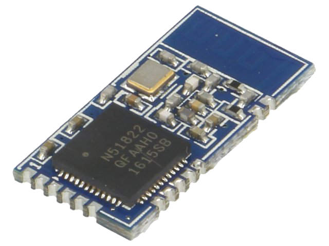
It doesn't have 32KHz crystal, but I program it using "Crystal Oscillator" from board menu of nrf5 arduino core.
As far as I understand some of the periferals and/or interrupts and/or timers is used by Mysensors stack and doesn't shut down when going to sleep, so it tries to use RTC, which is not available, so it wokes HFCLK, so it consumes extra current. A lot more than it should in sleep mode.I need help with this, as I am planning to build a bucnh of simple window sensors on this board and they doesn't require wake by timer, but will be woken by extrnal pin interrupt. But for now I just can't use Mysensors sleep function to do this, because as I have described it works not as expected. Hope to get some response from you guys.
-
-
To summarize, what I have for now.
-
Plain mysensors sketch with empty loop consumes - 16.6mA
-
The same sketch with
sleep(60000);in loop - 95-100uA -
The same sketch with
pinMode(10, INPUT_PULLUP);andsleep(10, FALLING, 0);- 1mA -
The sketch based on Nordicsemi example from here https://github.com/NordicPlayground/nrf51-powerdown-examples/blob/master/system_on_wakeup_on_gpio/main.c
void setup() {
  NRF_GPIO->PIN_CNF[10] = ((uint32_t)GPIO_PIN_CNF_DIR_Input        << GPIO_PIN_CNF_DIR_Pos)
                          | ((uint32_t)GPIO_PIN_CNF_INPUT_Connect    << GPIO_PIN_CNF_INPUT_Pos)
                          | ((uint32_t)GPIO_PIN_CNF_PULL_Pullup      << GPIO_PIN_CNF_PULL_Pos)
                          | ((uint32_t)GPIO_PIN_CNF_DRIVE_S0S1       << GPIO_PIN_CNF_DRIVE_Pos)
                          | ((uint32_t)GPIO_PIN_CNF_SENSE_Low   << GPIO_PIN_CNF_SENSE_Pos);
  NRF_GPIOTE->INTENSET = GPIOTE_INTENSET_PORT_Msk;
  NVIC_EnableIRQ(GPIOTE_IRQn);
  delay(2000);
  NRF_RTC1->TASKS_STOP = 1;
}

void loop() {
  NRF_RADIO->TASKS_DISABLE = 1;
  NRF_CLOCK->TASKS_HFCLKSTOP = 1;
  __WFE();
  __SEV();
  __WFE();
}

void GPIOTE_IRQHandler(void)
{
  // This handler will be run after wakeup from system ON (GPIO wakeup)
  if (NRF_GPIOTE->EVENTS_PORT)
  {
    NRF_GPIOTE->EVENTS_PORT = 0;

  }
}
While
delay(2000);consumes 4mA, after stopping RTC and HFCLK and going to sleep as expected consumes less than 10uA (my meter can't read less than that so it shows just 0).- The same code adapted for use with mysensors library:
#define MY_RADIO_NRF5_ESB

#include <MySensors.h>

void setup()
{
  NRF_GPIO->PIN_CNF[10] = ((uint32_t)GPIO_PIN_CNF_DIR_Input        << GPIO_PIN_CNF_DIR_Pos)
                          | ((uint32_t)GPIO_PIN_CNF_INPUT_Connect    << GPIO_PIN_CNF_INPUT_Pos)
                          | ((uint32_t)GPIO_PIN_CNF_PULL_Pullup      << GPIO_PIN_CNF_PULL_Pos)
                          | ((uint32_t)GPIO_PIN_CNF_DRIVE_S0S1       << GPIO_PIN_CNF_DRIVE_Pos)
                          | ((uint32_t)GPIO_PIN_CNF_SENSE_Low   << GPIO_PIN_CNF_SENSE_Pos);
  NRF_GPIOTE->INTENSET = GPIOTE_INTENSET_PORT_Msk;
  NVIC_EnableIRQ(GPIOTE_IRQn);
}

void loop()
{
  transportDisable();
  NRF_POWER->TASKS_LOWPWR = 1;
  NRF_RTC1->TASKS_STOP = 1;
  MY_HW_RTC->POWER = 0;
  MY_HW_RTC->INTENCLR = RTC_INTENSET_COMPARE0_Msk;
  MY_HW_RTC->EVTENCLR = RTC_EVTENSET_COMPARE0_Msk;
  NRF_ADC->TASKS_STOP = 1;
  NRF_ADC->ENABLE = 0;
  NRF_CLOCK->TASKS_HFCLKSTOP = 1;
  NRF_UART0->TASKS_STOPRX = 1;
  NRF_UART0->TASKS_STOPTX = 1;
  NRF_UART0->TASKS_SUSPEND = 1;
  __WFE();
  __SEV();
  __WFE();
}

void GPIOTE_IRQHandler(void)
{
  // This handler will be run after wakeup from system ON (GPIO wakeup)
  if (NRF_GPIOTE->EVENTS_PORT)
  {
    NRF_GPIOTE->EVENTS_PORT = 0;

  }
}
I know that this code is wrong, as it doesn't enable peripherals after wake up, and it I just took chunks of code from different places trying to disable whatever is running by mysensors and consumes that extra current. So in sleep this code consumes 200-230uA.
All is running on WT15822 board like this:
It doesn't have 32KHz crystal, but I program it using "Crystal Oscillator" from board menu of nrf5 arduino core.
As far as I understand some of the periferals and/or interrupts and/or timers is used by Mysensors stack and doesn't shut down when going to sleep, so it tries to use RTC, which is not available, so it wokes HFCLK, so it consumes extra current. A lot more than it should in sleep mode.I need help with this, as I am planning to build a bucnh of simple window sensors on this board and they doesn't require wake by timer, but will be woken by extrnal pin interrupt. But for now I just can't use Mysensors sleep function to do this, because as I have described it works not as expected. Hope to get some response from you guys.
Great work @monte, thanks for sharing.
Just to set your expectations correctly: Very few MySensors users have tried nrf5 so far, so the combined experience is quite low. Hopefully someone has an idea on how to help you, but it could very well be that you're the community's most experienced user in this area thanks to your work.
-
-
Hello guys. Finally I've got some nrf51288 boards, like used here: https://www.openhardware.io/view/510/Button-cell-Temperature-Humidity-sensor I've hooked it up to ST Link, uploaded test sketch and everything worked fine. Then I tried to put it to sleep and measure power consumption. The best number I'm getting is 550uA... And it seems like something is completely wrong with this. Either my readings, or some bug in new version of Mysensors library or nrf5 arduino core.
To be sure it's not particular chip's bug I've checked both I've got, no differences. I've also checked current on stock BLE firmware from manufacturer it was running when they came. It was around 120uA - 200uA while presenting via bluetooth. So I guess it can't be that my readings are completely wrong. But then how can it be that bluetooth presenting consume less current than sleeping?
For now I couldn't find a solution or any hint for this, so I apologize If I am missing something, but I need help.EDIT: I might just delete this post, but maybe someone will search for the same solution. Long story short 600uA extra is due to the lack of low frequency crystal onboard. It makes HFCLK to not shutdown and draws current during a sleep. I knew, that synth RTC will take more current but I didn't expect it to be that much.
Another question is why sleep that depends on pin change and seems doesn't require RTC consumes 1ma? I'm confused...@monte thé HFCLK is on because of a hardware bug in nrf51822 when you want to wake up using pin interrupt. You have to use PORT interrupt to go really low (around 5uA).
I made some (dirty) test code to validate that with MySensors but there was not much interest in that in the forum so I switched to something else. I will not use nrf51822 but nrf52832/40, they became really cheap now and don't have this hardware bug.
-
@monte thé HFCLK is on because of a hardware bug in nrf51822 when you want to wake up using pin interrupt. You have to use PORT interrupt to go really low (around 5uA).
I made some (dirty) test code to validate that with MySensors but there was not much interest in that in the forum so I switched to something else. I will not use nrf51822 but nrf52832/40, they became really cheap now and don't have this hardware bug.
-
@nca78 By the way, were you ever able to get multiple different interrupts working?
Here we are a year later, and I guess there's still no final silicon for the nRF52840?
-
@neverdie it works with the code I posted.
There are a few modules available with nrf52840 now so I guess final silicon is out. But it's only available in WCSP format I think so you won't see the chip alone.
@nca78 The Rev C (COO) parts are available now and they are the production parts. (Symmetry and Nordic's other distributors have these in stock) There will be a respin of this to a Rev D to fix the REG0 issue. FYI, the current nRF52840 package is not a WCSP. It is a aQFN™ package. The nRF52840-Dongle is also available now. Go forth and design......
-
@monte thé HFCLK is on because of a hardware bug in nrf51822 when you want to wake up using pin interrupt. You have to use PORT interrupt to go really low (around 5uA).
I made some (dirty) test code to validate that with MySensors but there was not much interest in that in the forum so I switched to something else. I will not use nrf51822 but nrf52832/40, they became really cheap now and don't have this hardware bug.
@nca78 well, after 2 nights of intense trying and failing I've got code to work as expected. And yes, it works with PORT interrupt, its kinda more code for you to write in compare to simply using attachInterrupt function, but I'm okay with that. For me double the price of 52832 compared to 51822 is significant. And for now, for a simple sensor stuff as we do with mysensors I don't really see any advantages except that interrupt bug fixed.
Also I've found that Mysensors sleep function for nrf5 is missing one very important command, I don't know why, maybe it is nrf51822 specific and thus @d00616 missed it but in current version of Mysensors library it doesn't disable UART before sleep, that's why I was getting 120-200uA current during sleep. I still don't really know how to make pull requests on github, so I guess I will just post it here:
line 290 of MyHwNRF5.cpp should contain:NRF_UART0->ENABLE=0;and line 327:NRF_UART0->ENABLE=1;respectively. That completely disables UART on nrf51822.
I will post my complete sketch later, when I will finish it, maybe someone who strugles as I did will find it useful. Also I think we need to somehow combine all examples that were posted in this thread or at least put a list of them with links, because looking through 1654 posts is not an easy task, especially if you not sure what you are looking for exactly. -
@nca78 well, after 2 nights of intense trying and failing I've got code to work as expected. And yes, it works with PORT interrupt, its kinda more code for you to write in compare to simply using attachInterrupt function, but I'm okay with that. For me double the price of 52832 compared to 51822 is significant. And for now, for a simple sensor stuff as we do with mysensors I don't really see any advantages except that interrupt bug fixed.
Also I've found that Mysensors sleep function for nrf5 is missing one very important command, I don't know why, maybe it is nrf51822 specific and thus @d00616 missed it but in current version of Mysensors library it doesn't disable UART before sleep, that's why I was getting 120-200uA current during sleep. I still don't really know how to make pull requests on github, so I guess I will just post it here:
line 290 of MyHwNRF5.cpp should contain:NRF_UART0->ENABLE=0;and line 327:NRF_UART0->ENABLE=1;respectively. That completely disables UART on nrf51822.
I will post my complete sketch later, when I will finish it, maybe someone who strugles as I did will find it useful. Also I think we need to somehow combine all examples that were posted in this thread or at least put a list of them with links, because looking through 1654 posts is not an easy task, especially if you not sure what you are looking for exactly.@monte But you solve your issue with the WT15822 board? Can you please share your sketch?
Is the range good of the WT15822 board?
I have started sketching to create a couple of new simple temp / hum sensors (WT15822, si7021 and cr2032) and want to know if I can use WT15822 before I order a pcb :)
-
@monte But you solve your issue with the WT15822 board? Can you please share your sketch?
Is the range good of the WT15822 board?
I have started sketching to create a couple of new simple temp / hum sensors (WT15822, si7021 and cr2032) and want to know if I can use WT15822 before I order a pcb :)
@smilvert I think I solved issues I mentioned. But I don't have final code yet as I am waiting for parts to arrive for my board. But I think there is no problem using WT51822 board except that you'll have to manually set PORT interrupt and also set pin SENSE register which is cannot be done with arduino function
pinMode().
So I guess you can order PCBs if you want, I'm going to post final sketch with explanations at the end of the month. -
Hey,
I got an issue with getting my custom board with SI7021 under 450uA.
- Ebyte 52832
I use the Sparkfun library to read data from itI did some deductions.-
When I insert sensor.begin(); it starts using quite an amount of power when sleeping. -
When I remove this line it shoots down to around the 10ua. -
I tried 2 board, that are identical, with exactly the same results
This happens also when I use this code on a board that doesn't have a SI7021 soldered onto it. So I don't think it is the SI7021.
SDA/SCL are both connected with a 10K pull-up.My guess is that is has something to do with it being a thing with the NRF.the readings from the SI7021 seem legit, so it works, but the sleep current wrecks my battery life.Is there someone that can help me with this?The same old story, when you finally go looking for help, you find your answer.
It indeed looks like it has something to do with the NRF52.
as mentioned: https://github.com/sandeepmistry/arduino-nRF5/issues/291#issuecomment-407492282A workaround for the symptoms is known and described at:
http://infocenter.nordicsemi.com/index.jsp?topic=%2Fcom.nordic.infocenter.nrf52832.Rev1.errata%2Fanomaly_832_89.html&cp=2_2_1_0_1_26Solution:
you need to add the following lines to shutdown the i2c:
NRF_TWI1->ENABLE=TWI_ENABLE_ENABLE_Disabled << TWI_ENABLE_ENABLE_Pos;
*(volatile uint32_t *)0x40004FFC = 0;
*(volatile uint32_t *)0x40004FFC;
*(volatile uint32_t *)0x40004FFC = 1;
And when you need some readings, just call "sensor.begin(); " to go on your way.
I measure 00.01 mA now, (multimeter doesnt go into the uA ranges :) )
Maybe @d00616, or someone else can work this into a standard routine (this is way out of my league, i can dump it into my sketch, but dont have a clue what it is doing)
-
Hey,
I got an issue with getting my custom board with SI7021 under 450uA.
- Ebyte 52832
I use the Sparkfun library to read data from itI did some deductions.-
When I insert sensor.begin(); it starts using quite an amount of power when sleeping. -
When I remove this line it shoots down to around the 10ua. -
I tried 2 board, that are identical, with exactly the same results
This happens also when I use this code on a board that doesn't have a SI7021 soldered onto it. So I don't think it is the SI7021.
SDA/SCL are both connected with a 10K pull-up.My guess is that is has something to do with it being a thing with the NRF.the readings from the SI7021 seem legit, so it works, but the sleep current wrecks my battery life.Is there someone that can help me with this?The same old story, when you finally go looking for help, you find your answer.
It indeed looks like it has something to do with the NRF52.
as mentioned: https://github.com/sandeepmistry/arduino-nRF5/issues/291#issuecomment-407492282A workaround for the symptoms is known and described at:
http://infocenter.nordicsemi.com/index.jsp?topic=%2Fcom.nordic.infocenter.nrf52832.Rev1.errata%2Fanomaly_832_89.html&cp=2_2_1_0_1_26Solution:
you need to add the following lines to shutdown the i2c:
NRF_TWI1->ENABLE=TWI_ENABLE_ENABLE_Disabled << TWI_ENABLE_ENABLE_Pos;
*(volatile uint32_t *)0x40004FFC = 0;
*(volatile uint32_t *)0x40004FFC;
*(volatile uint32_t *)0x40004FFC = 1;
And when you need some readings, just call "sensor.begin(); " to go on your way.
I measure 00.01 mA now, (multimeter doesnt go into the uA ranges :) )
Maybe @d00616, or someone else can work this into a standard routine (this is way out of my league, i can dump it into my sketch, but dont have a clue what it is doing)
@omemanti It seems like some peripherals are not shut down before sleep. As library you've mentioned uses Wire library, it must be TWI (i2c) interface that are active during sleep and consumes extra power. I'm afraid that you will have to manually disable/enable TWI around sleep routine.
EDIT: I see you've found an answer by yourself. Just want to clarify that it isn't nrf5 chip's fault, it just how it intended to work. It doesn't automagically disable all peripherals during sleep. So, someone should write low current sleep library for nrf5 specifically, that will check the state of peripherals before sleep and disable them if needed. -
Anyone played around with Nordic's nRF52840 dongle? They're $10 each, and a few places have them in stock.
https://www.nordicsemi.com/eng/Products/nRF52840-DongleNordic finally has a v1.0 product specification for the nRF52840, not just the silly v0.5 that they had posted for so long. http://infocenter.nordicsemi.com/pdf/nRF52840_PS_v1.0.pdf
It has 256K RAM and 1MB of flash. I'm having difficulty imagining which applications would require that much of either one. If it were free, that would be great, but I'm afraid the large RAM becomes an energy drain. For instance, it consumes 3.16µA with System ON, full 256 kB RAM retention, and wake on RTC.
On the other hand, it consumes 0.4uA of current if System OFF, no RAM retention, and wake on reset
It consumes 16.4ma if transmitting at full power (8dBm) with DC-DC engaged.
If compared to LoRa, it's going to lose on range. However, the question is: will it be good enough in a large or otherwise difficult home environment? The specs say it should be better than either nRF24L01 and nRF52832, which seem better suited to smaller dwellings. Maybe (?) the question can be answered with a couple of dongles.
-
Anyone played around with Nordic's nRF52840 dongle? They're $10 each, and a few places have them in stock.
https://www.nordicsemi.com/eng/Products/nRF52840-DongleNordic finally has a v1.0 product specification for the nRF52840, not just the silly v0.5 that they had posted for so long. http://infocenter.nordicsemi.com/pdf/nRF52840_PS_v1.0.pdf
It has 256K RAM and 1MB of flash. I'm having difficulty imagining which applications would require that much of either one. If it were free, that would be great, but I'm afraid the large RAM becomes an energy drain. For instance, it consumes 3.16µA with System ON, full 256 kB RAM retention, and wake on RTC.
On the other hand, it consumes 0.4uA of current if System OFF, no RAM retention, and wake on reset
It consumes 16.4ma if transmitting at full power (8dBm) with DC-DC engaged.
If compared to LoRa, it's going to lose on range. However, the question is: will it be good enough in a large or otherwise difficult home environment? The specs say it should be better than either nRF24L01 and nRF52832, which seem better suited to smaller dwellings. Maybe (?) the question can be answered with a couple of dongles.
@neverdie I want to, but only shop that can send me with free shipping (and not 75$ like the others) is Arrow, and it's not yet in stock there.
CDEByte sells some too now ... but with a small form factor & ceramic antenna, I'm afraid it will waste all the theoretical extra range... -
I guess maybe in your case the next best alternative would be the Fanstel nRF52840 modules, which should be drop-in upgrades to whatever PCB designs you may have had that used the Fanstel nRF52832 modules. I had previously posted a few:
https://www.openhardware.io/view/499/10-years-wireless-PIR-Sensor-on-just-one-set-of-3-AAs
https://www.openhardware.io/view/491/PA-LNA-nRF52832-ESP-LINK-Shield-for-Wemos-D1-Mini-ESP8266
https://www.openhardware.io/view/489/BT832X-Power-Amplified-nRF52832-Remote-Control-with-LNA
Fortunately, the remote control I posted would still consume zero current when not in use even with the nRF52840. :)I guess that PPI is unique to Nordic. I had previously supposed it was a part of the generic ARM chip design, but I didn't see it when I looked into the STM32 chips.
-
Come to think of it: with so much flash and RAM, I bet the nRF52840 could easily run micro Python. Now that would be interesting!
-
Come to think of it: with so much flash and RAM, I bet the nRF52840 could easily run micro Python. Now that would be interesting!
@neverdie
In fact it can.
Adafruit has a build of their Circuitpython (Micropython fork) for the nrf52832, and there's already an early alpha for the nrf52840.
As the 52840 has native USB, they can use Micropython as it was originally intended to be, with a virtual USB drive that contains all the user code files.
Hello! It looks like you're interested in this conversation, but you don't have an account yet.
Getting fed up of having to scroll through the same posts each visit? When you register for an account, you'll always come back to exactly where you were before, and choose to be notified of new replies (either via email, or push notification). You'll also be able to save bookmarks and upvote posts to show your appreciation to other community members.
With your input, this post could be even better 💗
Register Login