Arduino pro mini dead after flashing MYSbootloader.
-
After flashing node with MySensors bootloader i can still flash the node with ftdi but sketch no longer runs. Tried it with blink sketch. Does uploading the bootloader alter the fuses? I dont know whats going on :sweat:
when plugged into my board the led on the arduino just stays on, when i pull the pro mini out of the board and reset (while connected to ftdi) it blinks in cycles of 3x slow and 4x fast. As soon as i insert it in the node it goes to steady on. I know the board is good because a board with factory bootloader runs the sketch just fine. Can someone shine a (led)light:wink: on this
When i flash the original bootloader again everything works as expected. What am i missing here?
-
@jimmy-loyens maybe the size of the bootloaders is different and therefore requires different bootloader area configuration?
The size is defined by fuses btw.@yveaux sorry but "huh?" 😲
This is my first time trying ota, before i knew about the existance of bootloaders but thats about it. Dont meen to offend you but could you elaborate a bit
-
@yveaux sorry but "huh?" 😲
This is my first time trying ota, before i knew about the existance of bootloaders but thats about it. Dont meen to offend you but could you elaborate a bit
@jimmy-loyens ok found this: https://forum.arduino.cc/index.php?topic=70208.0
Now i only need to find out how big my bootloader is. I assume the size of the hex file.
-
@jimmy-loyens ok found this: https://forum.arduino.cc/index.php?topic=70208.0
Now i only need to find out how big my bootloader is. I assume the size of the hex file.
@jimmy-loyens Ok problem,
My bootloader hex is 6Kb = 6000b = 3000 wordsBOOTZ1|BOOTZ0
11=>256words = 512b
10=>512words = 1024b
01=>1024words = 2048b
00=>2048words = not enough:confused: :pensive:Am i understanding this correct?
Choosing the largest bootzone combination (11) didn't help :disappointed:
-
I found this on the forum:
"In the process of troubleshooting I found out that MYSBootloader needs to be compiled with the same channel settings as the gateway it connects to. "I think this is most likely the problem since i'm currently using a test-network with channel 5. I'll try changing the channel in the bootloader source and recompiling it.
-
@jimmy-loyens said in Arduino pro mini dead after flashing MYSbootloader.:
Dont meen to offend you but could you elaborate a bit
Yes I could, but you found out by yourself :+1:
Now you learned something new today ;-) -
@jimmy-loyens said in Arduino pro mini dead after flashing MYSbootloader.:
Dont meen to offend you but could you elaborate a bit
Yes I could, but you found out by yourself :+1:
Now you learned something new today ;-)@yveaux do you know what development ide i have to use to compile the bootloader? i cant find anything with google on this. I allready found where to change the RF channel in the source but i have no idea how to compile it into a hex file. Tried vs code but i probably have to install another extention
-
@yveaux do you know what development ide i have to use to compile the bootloader? i cant find anything with google on this. I allready found where to change the RF channel in the source but i have no idea how to compile it into a hex file. Tried vs code but i probably have to install another extention
@jimmy-loyens if you get enough help from people to manage building the bootloader, it would be fantastic if you could take some notes and share so we can publish a first version of a guide. I am curious myself and would like to try, and I've seen some questions in the forum earlier so it seems more people are interested.
I did a quick test, and it seems running make all is sufficient, provided that all tools are in the "right" place.
This was the result I got:Micke @ Quasi ~/workspace/MySensorsBootloaderRF24 development $ make all rm *.o rm: cannot remove '*.o': No such file or directory make: [Makefile:44: clean] Error 1 (ignored) rm *.elf rm: cannot remove '*.elf': No such file or directory make: [Makefile:45: clean] Error 1 (ignored) rm *.hex rm: cannot remove '*.hex': No such file or directory make: [Makefile:46: clean] Error 1 (ignored) "/cygdrive/c/Program Files (x86)/Arduino/hardware/tools/avr/bin/avr-gcc" -I"/cygdrive/c/Program Files (x86)/Arduino/hardware/tools/avr/avr/include/avr" -funsigned-char -funsigned-bitfields -DF_CPU=16000000L -DBAUD_RATE=115200 -Os -ffunction-sections -fdata-sections -fpack-struct -fshort-enums -mrelax -Wall -Wextra -Wundef -pedantic -mmcu=atmega328p -c -std=gnu99 -MD -MP -MF "MYSBootloader.d" -MT"MYSBootloader.d" -MT"MYSBootloader.o" MYSBootloader.c -o MYSBootloader.o In file included from Core.h:40:0, from MYSBootloader.c:81: HW.h:51:4: warning: #warning is a GCC extension #warning BAUD_RATE error greater than 2% ^ HW.h:51:4: warning: #warning BAUD_RATE error greater than 2% [-Wcpp] In file included from Core.h:45:0, from MYSBootloader.c:81: MySensorsBootloader.h:59:1: warning: 'inline' is not at beginning of declaration [-Wold-style-declaration] static bool inline sendMessage(void) { ^ "/cygdrive/c/Program Files (x86)/Arduino/hardware/tools/avr/bin/avr-gcc" -nostartfiles -Wl,-s -Wl,-static -Wl,-Map=".map" -Wl,--start-group -Wl,--end-group -Wl,--gc-sections -mrelax -Wl,-section-start=.text=0x7800 -mmcu=atmega328p -o MYSBootloader.elf MYSBootloader.o -lm "/cygdrive/c/Program Files (x86)/Arduino/hardware/tools/avr/bin/avr-objcopy" -O ihex -R .eeprom MYSBootloader.elf MYSBootloader.hex "/cygdrive/c/Program Files (x86)/Arduino/hardware/tools/avr/bin/avr-size" MYSBootloader.elf text data bss dec hex filename 2032 6 71 2109 83d MYSBootloader.elf Micke @ Quasi ~/workspace/MySensorsBootloaderRF24 development $ file MYSBootloader.elf MYSBootloader.elf: ELF 32-bit LSB executable, Atmel AVR 8-bit, version 1 (SYSV), statically linked, stripped Micke @ Quasi ~/workspace/MySensorsBootloaderRF24 development $ ls -l MYSBootloader.elf -rwxrwxr-x+ 1 Micke None 2480 Jan 24 21:59 MYSBootloader.elf -
@jimmy-loyens if you get enough help from people to manage building the bootloader, it would be fantastic if you could take some notes and share so we can publish a first version of a guide. I am curious myself and would like to try, and I've seen some questions in the forum earlier so it seems more people are interested.
I did a quick test, and it seems running make all is sufficient, provided that all tools are in the "right" place.
This was the result I got:Micke @ Quasi ~/workspace/MySensorsBootloaderRF24 development $ make all rm *.o rm: cannot remove '*.o': No such file or directory make: [Makefile:44: clean] Error 1 (ignored) rm *.elf rm: cannot remove '*.elf': No such file or directory make: [Makefile:45: clean] Error 1 (ignored) rm *.hex rm: cannot remove '*.hex': No such file or directory make: [Makefile:46: clean] Error 1 (ignored) "/cygdrive/c/Program Files (x86)/Arduino/hardware/tools/avr/bin/avr-gcc" -I"/cygdrive/c/Program Files (x86)/Arduino/hardware/tools/avr/avr/include/avr" -funsigned-char -funsigned-bitfields -DF_CPU=16000000L -DBAUD_RATE=115200 -Os -ffunction-sections -fdata-sections -fpack-struct -fshort-enums -mrelax -Wall -Wextra -Wundef -pedantic -mmcu=atmega328p -c -std=gnu99 -MD -MP -MF "MYSBootloader.d" -MT"MYSBootloader.d" -MT"MYSBootloader.o" MYSBootloader.c -o MYSBootloader.o In file included from Core.h:40:0, from MYSBootloader.c:81: HW.h:51:4: warning: #warning is a GCC extension #warning BAUD_RATE error greater than 2% ^ HW.h:51:4: warning: #warning BAUD_RATE error greater than 2% [-Wcpp] In file included from Core.h:45:0, from MYSBootloader.c:81: MySensorsBootloader.h:59:1: warning: 'inline' is not at beginning of declaration [-Wold-style-declaration] static bool inline sendMessage(void) { ^ "/cygdrive/c/Program Files (x86)/Arduino/hardware/tools/avr/bin/avr-gcc" -nostartfiles -Wl,-s -Wl,-static -Wl,-Map=".map" -Wl,--start-group -Wl,--end-group -Wl,--gc-sections -mrelax -Wl,-section-start=.text=0x7800 -mmcu=atmega328p -o MYSBootloader.elf MYSBootloader.o -lm "/cygdrive/c/Program Files (x86)/Arduino/hardware/tools/avr/bin/avr-objcopy" -O ihex -R .eeprom MYSBootloader.elf MYSBootloader.hex "/cygdrive/c/Program Files (x86)/Arduino/hardware/tools/avr/bin/avr-size" MYSBootloader.elf text data bss dec hex filename 2032 6 71 2109 83d MYSBootloader.elf Micke @ Quasi ~/workspace/MySensorsBootloaderRF24 development $ file MYSBootloader.elf MYSBootloader.elf: ELF 32-bit LSB executable, Atmel AVR 8-bit, version 1 (SYSV), statically linked, stripped Micke @ Quasi ~/workspace/MySensorsBootloaderRF24 development $ ls -l MYSBootloader.elf -rwxrwxr-x+ 1 Micke None 2480 Jan 24 21:59 MYSBootloader.elf@mfalkvidd what software did you use for this? (I'm on win10 pc, not linux) I'm downloading avr studio right now, dont know if its possible with this software. I have never done anything like this. But hey there is a first time for everything.😁
I have read on the forum and github that @Guillermo-Schimmel has successfully compiled the MYSbootloader for 8MHz. I'll try asking him for some clues.
-
@yveaux do you know what development ide i have to use to compile the bootloader? i cant find anything with google on this. I allready found where to change the RF channel in the source but i have no idea how to compile it into a hex file. Tried vs code but i probably have to install another extention
@jimmy-loyens https://github.com/guillebot/MYSensors-Bootloaders
The bootloader for all the channels, in 1, 8 and 16MHz flavor.
-
@jimmy-loyens if you get enough help from people to manage building the bootloader, it would be fantastic if you could take some notes and share so we can publish a first version of a guide. I am curious myself and would like to try, and I've seen some questions in the forum earlier so it seems more people are interested.
I did a quick test, and it seems running make all is sufficient, provided that all tools are in the "right" place.
This was the result I got:Micke @ Quasi ~/workspace/MySensorsBootloaderRF24 development $ make all rm *.o rm: cannot remove '*.o': No such file or directory make: [Makefile:44: clean] Error 1 (ignored) rm *.elf rm: cannot remove '*.elf': No such file or directory make: [Makefile:45: clean] Error 1 (ignored) rm *.hex rm: cannot remove '*.hex': No such file or directory make: [Makefile:46: clean] Error 1 (ignored) "/cygdrive/c/Program Files (x86)/Arduino/hardware/tools/avr/bin/avr-gcc" -I"/cygdrive/c/Program Files (x86)/Arduino/hardware/tools/avr/avr/include/avr" -funsigned-char -funsigned-bitfields -DF_CPU=16000000L -DBAUD_RATE=115200 -Os -ffunction-sections -fdata-sections -fpack-struct -fshort-enums -mrelax -Wall -Wextra -Wundef -pedantic -mmcu=atmega328p -c -std=gnu99 -MD -MP -MF "MYSBootloader.d" -MT"MYSBootloader.d" -MT"MYSBootloader.o" MYSBootloader.c -o MYSBootloader.o In file included from Core.h:40:0, from MYSBootloader.c:81: HW.h:51:4: warning: #warning is a GCC extension #warning BAUD_RATE error greater than 2% ^ HW.h:51:4: warning: #warning BAUD_RATE error greater than 2% [-Wcpp] In file included from Core.h:45:0, from MYSBootloader.c:81: MySensorsBootloader.h:59:1: warning: 'inline' is not at beginning of declaration [-Wold-style-declaration] static bool inline sendMessage(void) { ^ "/cygdrive/c/Program Files (x86)/Arduino/hardware/tools/avr/bin/avr-gcc" -nostartfiles -Wl,-s -Wl,-static -Wl,-Map=".map" -Wl,--start-group -Wl,--end-group -Wl,--gc-sections -mrelax -Wl,-section-start=.text=0x7800 -mmcu=atmega328p -o MYSBootloader.elf MYSBootloader.o -lm "/cygdrive/c/Program Files (x86)/Arduino/hardware/tools/avr/bin/avr-objcopy" -O ihex -R .eeprom MYSBootloader.elf MYSBootloader.hex "/cygdrive/c/Program Files (x86)/Arduino/hardware/tools/avr/bin/avr-size" MYSBootloader.elf text data bss dec hex filename 2032 6 71 2109 83d MYSBootloader.elf Micke @ Quasi ~/workspace/MySensorsBootloaderRF24 development $ file MYSBootloader.elf MYSBootloader.elf: ELF 32-bit LSB executable, Atmel AVR 8-bit, version 1 (SYSV), statically linked, stripped Micke @ Quasi ~/workspace/MySensorsBootloaderRF24 development $ ls -l MYSBootloader.elf -rwxrwxr-x+ 1 Micke None 2480 Jan 24 21:59 MYSBootloader.elf@mfalkvidd Compiling the bootloader in a linux machine is as easy as running make, given than you have devel tools and avr-gcc installed.
-
@jimmy-loyens https://github.com/guillebot/MYSensors-Bootloaders
The bootloader for all the channels, in 1, 8 and 16MHz flavor.
@guillermo-schimmel wow thanks alot, saves me alot of searching and work. Thanks
-
@mfalkvidd what software did you use for this? (I'm on win10 pc, not linux) I'm downloading avr studio right now, dont know if its possible with this software. I have never done anything like this. But hey there is a first time for everything.😁
I have read on the forum and github that @Guillermo-Schimmel has successfully compiled the MYSbootloader for 8MHz. I'll try asking him for some clues.
-
Now i used the 8MHz external Xtal bootloader for RFchannel 5 (GW is on channel 5) that i got from @Guillermo-Schimmel (thanks again) to flash onto my arduino pro mini using avrdudess (less hassle with editing boards.txt file of arduinoIDE), but still same result.
I think mr bootloader is working though because the onboard led of the node behaves like this:
(node power on) 10101-000000000000000000-10101-0-
1111111111111111111111-0-1111111111111111111111-0-1111111111111111111111-0-1111111111111111111111-0-...
(GW online)-11111111111111111111111111111111111111111111111111111111111111111111...
So as long as GW is not online the led stays on for long period then goes off for very short period (i think its looking for the gateway), once GW comes online the onboard led of the node stays on (node has seen gateway online). If i unpower the GW at this point the node onboard led stays on until i reset node.
It looks like the bootloader is working and detects the GW comming online, but for some reason it doesnt jump on to the programmemory.
I have the node programmed with mysensors sketch on RFchannel 5 and GW with mqtt client on RF-channel 5. Added "#define MY_OTA_FIRMWARE_FEATURE" for both node and GW (even though i think its not nessecairy for the GW). are there any other defines i should add to the sketch(es)?
@Guillermo-Schimmel I have some more questions for you:
-Where the bootloaders compiled with the standard spi pins, being: "#define SPI_PINS_CE9_CSN10"
-It says in the make file on github (MYSbootloader): "ISP_EFUSE = 06" but I cant seem to set the E fuse like this. For me only possible values are: F8/F9/FA/FB/FC/FD/FE/FF (this is probably not the problem because this only sets brown-out bits, just curious)
-Did you allso have this problem when starting to use MYSbootloaderI'll keep trying and searching :smile: :thinking_face: :nerd_face:
Maybe another channel will help.
@jimmy-loyens Ok, this answers the question about the E fuse:
"
That's why :0x06 = 00000110
0xFE = 11111110
are doing the same job for the extended fuse. It depends of the tool you use for burning this fuse. Simply, if you get this warning, use the "equivalent".
" -
Now i used the 8MHz external Xtal bootloader for RFchannel 5 (GW is on channel 5) that i got from @Guillermo-Schimmel (thanks again) to flash onto my arduino pro mini using avrdudess (less hassle with editing boards.txt file of arduinoIDE), but still same result.
I think mr bootloader is working though because the onboard led of the node behaves like this:
(node power on) 10101-000000000000000000-10101-0-
1111111111111111111111-0-1111111111111111111111-0-1111111111111111111111-0-1111111111111111111111-0-...
(GW online)-11111111111111111111111111111111111111111111111111111111111111111111...
So as long as GW is not online the led stays on for long period then goes off for very short period (i think its looking for the gateway), once GW comes online the onboard led of the node stays on (node has seen gateway online). If i unpower the GW at this point the node onboard led stays on until i reset node.
It looks like the bootloader is working and detects the GW comming online, but for some reason it doesnt jump on to the programmemory.
I have the node programmed with mysensors sketch on RFchannel 5 and GW with mqtt client on RF-channel 5. Added "#define MY_OTA_FIRMWARE_FEATURE" for both node and GW (even though i think its not nessecairy for the GW). are there any other defines i should add to the sketch(es)?
@Guillermo-Schimmel I have some more questions for you:
-Where the bootloaders compiled with the standard spi pins, being: "#define SPI_PINS_CE9_CSN10"
-It says in the make file on github (MYSbootloader): "ISP_EFUSE = 06" but I cant seem to set the E fuse like this. For me only possible values are: F8/F9/FA/FB/FC/FD/FE/FF (this is probably not the problem because this only sets brown-out bits, just curious)
-Did you allso have this problem when starting to use MYSbootloaderI'll keep trying and searching :smile: :thinking_face: :nerd_face:
Maybe another channel will help.
@jimmy-loyens Seems like i didn't need to add the define:
"@tlustoch You need to enable MY_OTA_FIRMWARE_FEATURE only if you use DualOptiBoot.
With MYSBootloader, you don't need 😉I use MYSBootloader 1.3 pre-release with mysensors 2.0. You can find it here : https://forum.mysensors.org/topic/3453/mysbootloader-1-3-pre-release-myscontroller-1-0-0beta
And yes it usable with 8 MHZ internal clock config if you burn the bootloader with 8Mhz internal clock setting."
EDIT:
Removing "MY_OTA_FIRMWARE_FEATURE" was not the solution -
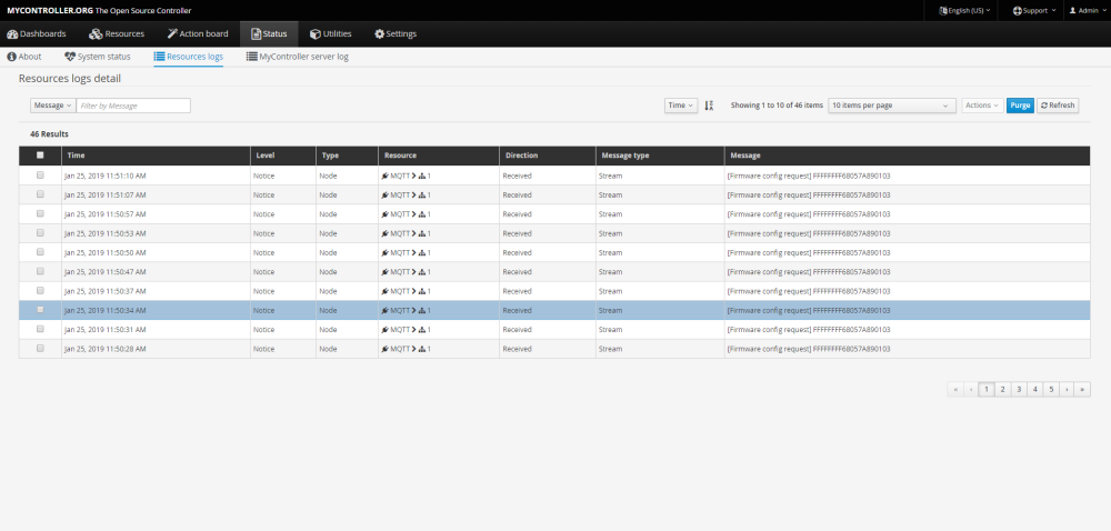
Ok, update:
When i look in MYController under "status=>resources logs" i can see the node continuously requesting firmware config, so i'm 100% shure the bootloader is good. I'm just not shure what's supposed to happen now from my side. I tried uploading firmware to the node OTA using "resources=>nodes=>actions=>upload firmware" but this doesn't seem to succeed and doesn't show up in the resources logs.
But atleast i have some new queries to google :grin: :wink:
In MQTT.fx I can allso see the node constantly sending: "mygateway1-out/1/255/4/0/0 FFFFFFFF68057A890103"
But if i see this correctly this would mean for node1 child255 Cmd=stream(OTA) Ack=0 Type=0(Dont know what 0 is in stream)Strange because my node has nodeID 107.:thinking_face:
Ok on closer inspection i can see in the resources log that the firmware config request comes from node1, so i tried updating firmware OTA of node 1, now i get a firmware config response inresources log.
UPDATE:
loaded the program back onto the node (changed batery level child from 0 to 255). Now node shows up with correct node ID in mycontroller. And now i get some output in serial monitor too, wich wasn't the case before. -
And BOOM it works!!!! :grin: :yum:
I just did my first FOTA update:+1: :+1: :+1: :+1: :+1: :+1:
Thanks to everyone who helped
-
And BOOM it works!!!! :grin: :yum:
I just did my first FOTA update:+1: :+1: :+1: :+1: :+1: :+1:
Thanks to everyone who helped
@jimmy-loyens Great!
I have to say that the work done with the bootloader and mysensors is really good.
It is very nice when FOTA starts working.
Hello! It looks like you're interested in this conversation, but you don't have an account yet.
Getting fed up of having to scroll through the same posts each visit? When you register for an account, you'll always come back to exactly where you were before, and choose to be notified of new replies (either via email, or push notification). You'll also be able to save bookmarks and upvote posts to show your appreciation to other community members.
With your input, this post could be even better 💗
Register Login