NRF51-52 PA not support ???
-
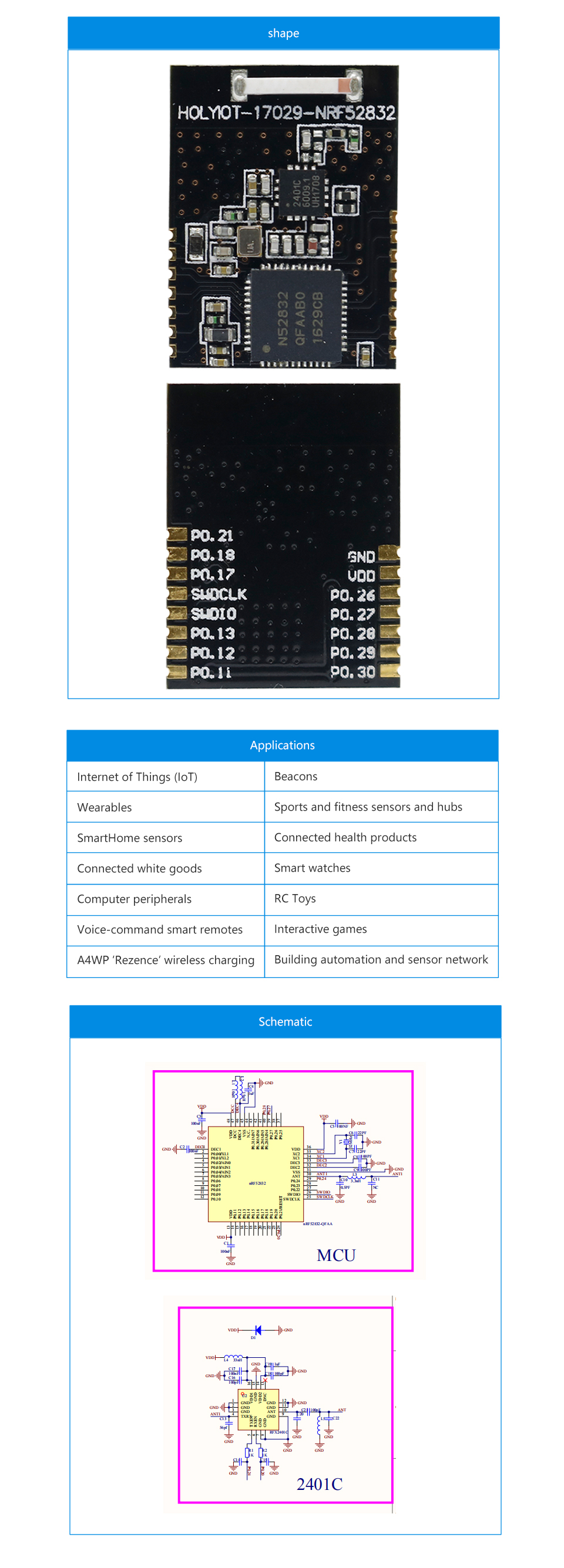
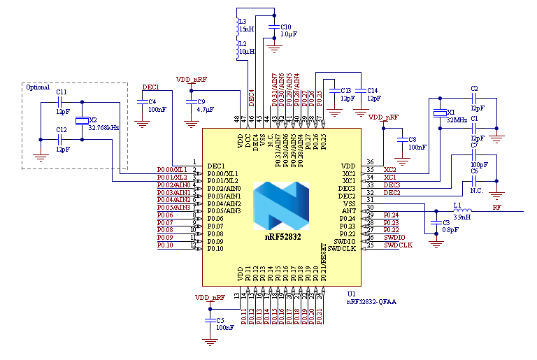
Hello, everyone. Today I tried to connect the module nRF52 PA. Module to work, but had a standard transmission\reception. The module includes a chip 2401С. As I understand it, the work modules nRF51-52 with PA is not implemented in the library as unconnected pins 20 and 24(the scheme). On the forum NORDIK found(for softdevice):
#ifdef APP_PA_LAN
    pa_lna_assist(24,20);//Pin 0.24 and pin 0.20
#endif
#ifdef APP_PA_LAN static void pa_lna_assist(uint32_t gpio_pa_pin, uint32_t gpio_lna_pin) { ret_code_t err_code; nrf_gpio_cfg_output(gpio_pa_pin); nrf_gpio_pin_clear(gpio_pa_pin); // nrf_gpio_cfg_output(gpio_lna_pin); nrf_gpio_pin_clear(gpio_lna_pin); // static const uint32_t gpio_toggle_ch = 0; static const uint32_t ppi_set_ch = 0; static const uint32_t ppi_clr_ch = 1; // Configure SoftDevice PA/LNA assist static ble_opt_t opt; memset(&opt, 0, sizeof(ble_opt_t)); // Common PA/LNA config opt.common_opt.pa_lna.gpiote_ch_id = gpio_toggle_ch; // GPIOTE channel opt.common_opt.pa_lna.ppi_ch_id_clr = ppi_clr_ch; // PPI channel for pin clearing opt.common_opt.pa_lna.ppi_ch_id_set = ppi_set_ch; // PPI channel for pin setting // PA config opt.common_opt.pa_lna.pa_cfg.active_high = 1; // Set the pin to be active high opt.common_opt.pa_lna.pa_cfg.enable = 1; // Enable toggling opt.common_opt.pa_lna.pa_cfg.gpio_pin = gpio_pa_pin; // The GPIO pin to toggle // LNA config opt.common_opt.pa_lna.lna_cfg.active_high = 1; // Set the pin to be active high opt.common_opt.pa_lna.lna_cfg.enable = 1; // Enable toggling opt.common_opt.pa_lna.lna_cfg.gpio_pin = gpio_lna_pin; // The GPIO pin to toggle err_code = sd_ble_opt_set(BLE_COMMON_OPT_PA_LNA, &opt); APP_ERROR_CHECK(err_code); } #endifdiagram of the module:
What to do? Help!!!
-
-
-
-
Seems consistent with another user’s experience: https://github.com/mysensors/MySensors/issues/1265
@mfalkvidd This is about another (levels MY_NRF5_ESB_PA_LEVEL). I had another problem, the signal amplification on the module with the 2401c chip did not work. But I somehow forced the module to increase the range :) The chips nFR51-52 no pins VDD_PA....
-
Hello,
I see two issues with this schematic. 1) The Cap C3 looks like it says 100nf. In the non-amplified use, this should be at least 4.7uF. If you are using a PA I would suggest a even larger value be used.
PO.25 and PO.26 if not used should be tied to ground. If used then they should each have a 12pF cap to ground. The internal bonding wires on the QFN package picks up some stray RF and will probably not pass any agency testing in Korea or Japan. This is probably not that important for personal use.
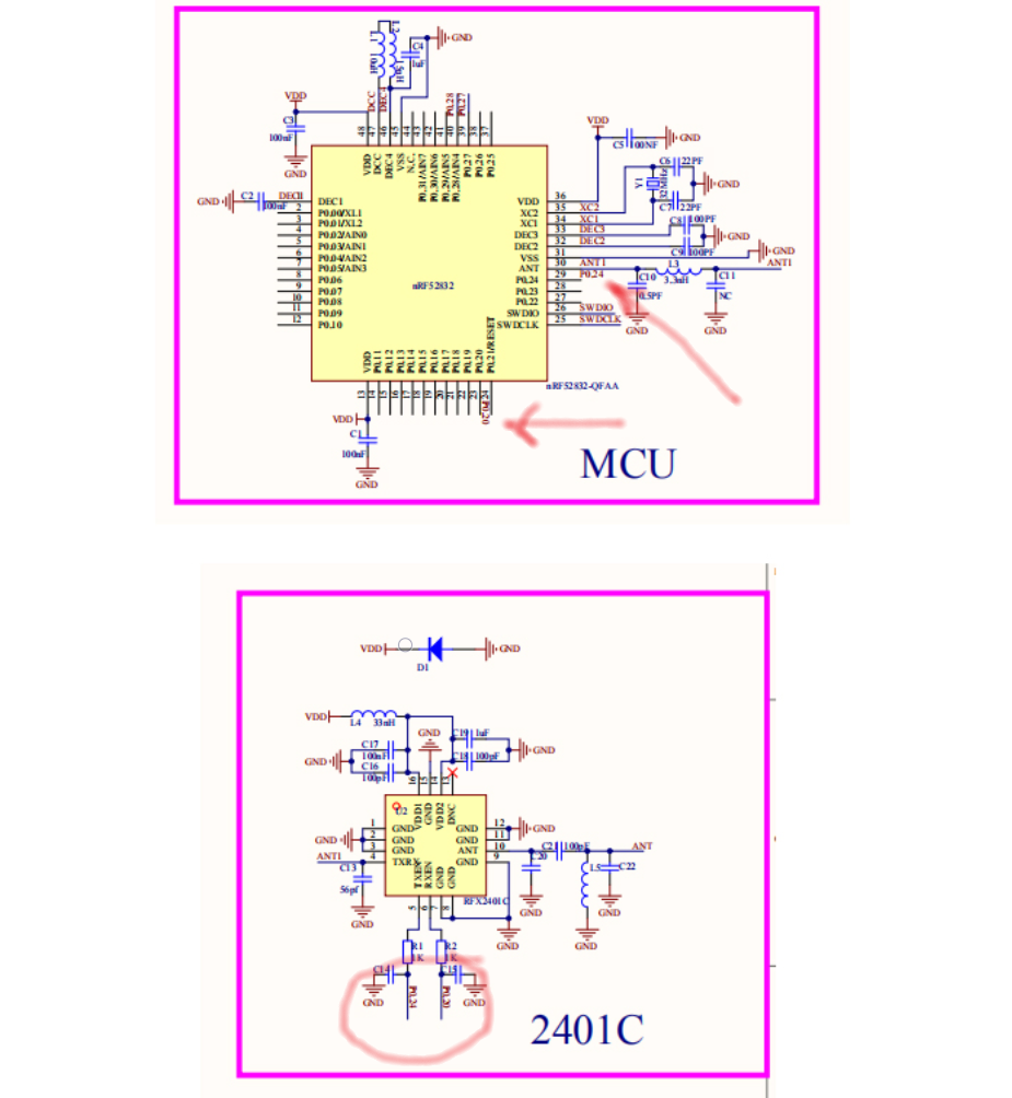
@jokgi I don't know what you mean. I'm not at all sure that your recommendations would be enough, I have a completely different solution. It is exclusively software. Maybe you can explain ...more details? where this scheme? С3 is understandable. Why should 25 and 26 be be tied to ground (if not used)? But none the less thank you for your interest in the topic and your comment. Now I have radio module with amplifier works, until tested on 200 metres, all normally, consumption in transfer 16mA. The problem is that the mysensors library offers no solution for amplified radio modules. Pins 20 and 24 are used as GPIOs. There is no #def available to initialize pins as TX RX gain controls. For myself, I did it, it is quite simple, but nevertheless. ...A more subtle approach is needed to make changes to the library.
-
Hi, everybody. Modules nRF5 with RFX2401(signal amplifier) control the amplifier from the legs of the microcontroller, as a rule, r0.20 and P0.24.
Do I understand correctly that gain control is not implemented in mysensors for nRF5 modules with amplifiers???
It probably can be done from the sketch, including a strengthening of the:
digitalWrite(TXEN_PIN, high);
digitalWrite(RXEN_PIN, high);
send.(..
digitalWrite(TXEN_PIN, low);
wait.(..
digitalWrite(RXEN_PIN, low);
But there is also internal communication (which is formed inside, for example - find parent, registration..), the functionality of the repeater, how it should be? -
Hello, everyone. Today I tried to connect the module nRF52 PA. Module to work, but had a standard transmission\reception. The module includes a chip 2401С. As I understand it, the work modules nRF51-52 with PA is not implemented in the library as unconnected pins 20 and 24(the scheme). On the forum NORDIK found(for softdevice):
#ifdef APP_PA_LAN
    pa_lna_assist(24,20);//Pin 0.24 and pin 0.20
#endif
#ifdef APP_PA_LAN static void pa_lna_assist(uint32_t gpio_pa_pin, uint32_t gpio_lna_pin) { ret_code_t err_code; nrf_gpio_cfg_output(gpio_pa_pin); nrf_gpio_pin_clear(gpio_pa_pin); // nrf_gpio_cfg_output(gpio_lna_pin); nrf_gpio_pin_clear(gpio_lna_pin); // static const uint32_t gpio_toggle_ch = 0; static const uint32_t ppi_set_ch = 0; static const uint32_t ppi_clr_ch = 1; // Configure SoftDevice PA/LNA assist static ble_opt_t opt; memset(&opt, 0, sizeof(ble_opt_t)); // Common PA/LNA config opt.common_opt.pa_lna.gpiote_ch_id = gpio_toggle_ch; // GPIOTE channel opt.common_opt.pa_lna.ppi_ch_id_clr = ppi_clr_ch; // PPI channel for pin clearing opt.common_opt.pa_lna.ppi_ch_id_set = ppi_set_ch; // PPI channel for pin setting // PA config opt.common_opt.pa_lna.pa_cfg.active_high = 1; // Set the pin to be active high opt.common_opt.pa_lna.pa_cfg.enable = 1; // Enable toggling opt.common_opt.pa_lna.pa_cfg.gpio_pin = gpio_pa_pin; // The GPIO pin to toggle // LNA config opt.common_opt.pa_lna.lna_cfg.active_high = 1; // Set the pin to be active high opt.common_opt.pa_lna.lna_cfg.enable = 1; // Enable toggling opt.common_opt.pa_lna.lna_cfg.gpio_pin = gpio_lna_pin; // The GPIO pin to toggle err_code = sd_ble_opt_set(BLE_COMMON_OPT_PA_LNA, &opt); APP_ERROR_CHECK(err_code); } #endifdiagram of the module:
What to do? Help!!!
@berkseo sorry for reviving an old topic but i will try something similar with nrf52840 and rfx2401C. Did you able to work it out with the code you provided. I dont have the module but i placed that code in the sketch and it compiled so im not sure if it is going to work. how did it work out for you?
-
I can't win the battle against nRF5 radio modules with amplifiers. Added a foot control to the radio driver for switching PA LNA. This works, but if you try to get bool send (), it very often returns false, although the message is successfully delivered to the recipient, I tried changing the value in NRF5_ESB_RAMP_UP_TIME, it does not help. Someone tried to achieve normal operation of nRF5 radio modules with amplifiers in Mysensors?
@berkseo the return value of send() indicates whether the sending node received an acknowledgement from the next node. If the next node (the gateway unless you have repeaters) received the message and send() still returns false, it usually means that the acknowledgement was lost.
Maybe the PA makes it possible for the sending node to reach the gateway, but the gateway is unable to reach the sending node?
-
@berkseo the return value of send() indicates whether the sending node received an acknowledgement from the next node. If the next node (the gateway unless you have repeaters) received the message and send() still returns false, it usually means that the acknowledgement was lost.
Maybe the PA makes it possible for the sending node to reach the gateway, but the gateway is unable to reach the sending node?
@mfalkvidd said in NRF51-52 PA not support ???:
the return value of send() indicates whether the sending node received an acknowledgement from the next node. If the next node (the gateway unless you have repeaters) received the message and send() still returns false, it usually means that the acknowledgement was lost.
Maybe the PA makes it possible for the sending node to reach the gateway, but the gateway is unable to reach the sending node?The network is simple, this node is nrf52 with an amplifier and a gateway with the nrf24 radio module with an amplifier. It would be strange if a gateway with an amplifier could not deliver ACK. Two moments, or I did a very bad control of the amplifier on the node nRF52 or in the radio driver itself, something is not working well, and may need some delay settings. If i send messages with an ECHO (soft ack) request, this works fine over very long distances. Hw ack does not work properly.
-
@berkseo said in NRF51-52 PA not support ???:
The network is simple, this node is nrf52 with an amplifier and a gateway with the nrf24 radio module with an amplifier. It would be strange if a gateway with an amplifier could not deliver ACK. Two moments, or I did a very bad control of the amplifier on the node nRF52 or in the radio driver itself, something is not working well, and may need some delay settings. If i send messages with an ECHO (soft ack) request, this works fine over very long distances. Hw ack does not work properly.
Someone was able to do this for mysensors? Gateways and repeaters on nrf5 with amplifier is a very, very cool topic.
Hello! It looks like you're interested in this conversation, but you don't have an account yet.
Getting fed up of having to scroll through the same posts each visit? When you register for an account, you'll always come back to exactly where you were before, and choose to be notified of new replies (either via email, or push notification). You'll also be able to save bookmarks and upvote posts to show your appreciation to other community members.
With your input, this post could be even better 💗
Register Login