[SOLVED] MQTT gateway based on Arduino Uno - Uno compatible W5100 Ethernet shield - RFM69HW radio
-
Hi Folks,
I'm new to MySensors, so before beginning building things, I read the docs, search the forum, etc., to be able to form me an idea how to start.
First taking the docs: https://www.mysensors.org/build/ethernet_gateway and https://www.mysensors.org/build/mqtt_gateway
The MQTT gateway is based on the ethernet gateway, so we are starting there.
The recommandation is to use a W5100 Ethernet module. This module has problems sharing SPI with the radio, so it is proposed to use soft-spi for the radio.
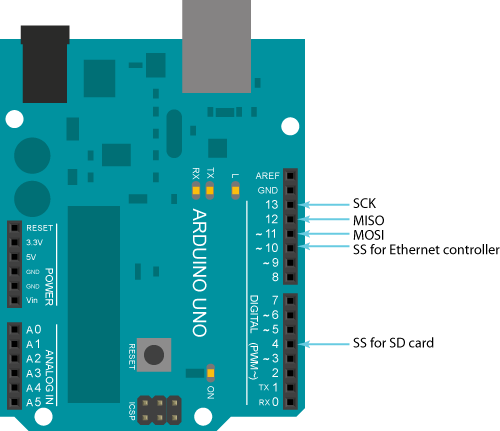
The W5100 ethernet shield module is hardware wired:

The radio should then be wired for soft-spi following the docs.
Because there is no example for a RFM69HW, I imagine that we must follow the same schematic as for the NRF24L01 radio.The given sketch is based on the use of a NRF24L01 radio, so when searching for the correct settings for RFM69HW in the forum, I stumbled on plenty of topics of people trying to build the same thing.
Some topics are already several years old, speaking about changing core ethernet libraries for the W5100 to disable the interrupts, others are building on forks of MySensors, forks of RFM69 library, etc.
I saw also a remark in a topic that for using soft-spi, we should use the new RFM69 driver in the MySensors lib.
In one of the topics with an own fork, was mentioned that, because the transactions in SPI where now supported in the RFM69 library, we can now wire also the RFM69HW radio to the same ports on the Arduino as the ethernet module.So, when reading all these topics, I did loose my view on the things
 :
:
With the current version of the MySensors library (2.3.1)- must we use soft-spi like mentioned in the docs or hardware spi like found in topics on the forum?
- https://forum.mysensors.org/topic/5109/solved-rfm69-based-nodes-unable-to-report-lib-version/45 : Are these forks now included into the main branch of MySensors?
-
Nobody has never build a gateway based on an Arduino Uno, a W5100 shield and a RFM69HW?
So I will answer my own questions

I did take my chance and choose to build first a gateway version using the hardware SPI bus (no soft spi) and I was lucky, it worked directly! So no need to try the soft-spi version.Because I did already build previously a sensor (https://www.mysensors.org/build/distance), I had all hardware already ready to be used.
So what is the used hardware?
- one standard Arduino Uno R3 (guine or chinese clone, DON'T BUY WAVGAT arduino uno types, they require specific hardware drivers in the Arduino IDE and this manufacturer doesn't update his own old drivers!!)(https://www.aliexpress.com/item/1pcs-Smart-Electronics-high-quality-UNO-R3-MEGA328P-CH340G-Compatible-NO-USB-CABLE-for-arduino/32830661533.html)
- one RFM69HW, version 868MHz (check what you can use at your country!)(https://www.aliexpress.com/item/Free-Shipping-RFM69HW-868Mhz-Transceiver-Module-High-Integrated-HopeRF-Wireless-868S2-Module-SPI-1-8-3/32810316806.html)
- one helical antenna (https://www.aliexpress.com/item/10PCS-868MHz-Helical-Antenna-2-15dBi-13mm-Stable-for-Remote-Contorl/32668155368.html)
- one W5100 shield pin compatible with an Arduino Uno (https://www.aliexpress.com/item/Free-Shipping-UNO-Shield-Ethernet-Shield-W5100-R3-UNO-Mega-2560-1280-328-UNR-R3-only/32502588687.html)
- one proto shield to build the RFM69HW radio on top of the W5100 shield (https://www.aliexpress.com/item/Standard-Proto-Screw-Shield-Board-For-Arduino-Compatible-Improved-version-support-A6-A7-Diy-Kit-Electronic/32832054800.html)
- one logic channel convertor between Arduino 5V and RFM69HW radio 3.3V (https://www.aliexpress.com/item/3-3V-5V-TXS0108E-8-Channel-Logic-Level-Bi-directional-Converter-Module-TXB0108-Mutual-Convert-Module/32916020205.html)
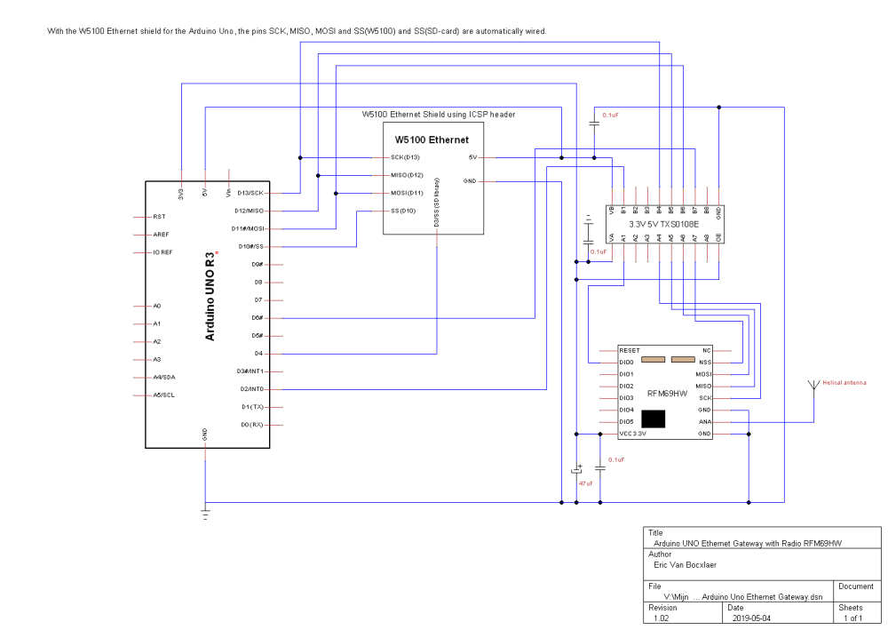
The hardware is wired following next schematic:

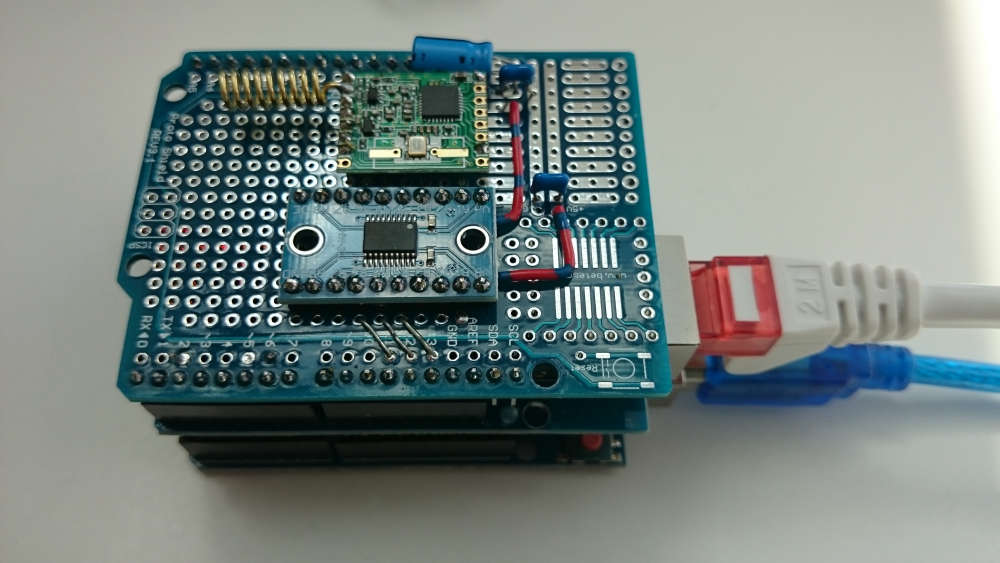
Connecting the RFM69HW hardware was somewhat tricky. The used pin headers on the RFM69HW are not following the standard spaced 2.54mm pin headers like on the Arduino print. I did not have a converter plate, so I soldered some hard wire into the RFM69HW pins and bend them into the pin holes from the protoboard. See photo.

So what about the software:- Arduino IDE version 1.8.9
- MySensors library 2.3.1
I did take as base the sketch found on the website https://www.mysensors.org/build/mqtt_gateway or https://github.com/mysensors/MySensors/blob/master/examples/GatewayW5100MQTTClient/GatewayW5100MQTTClient.ino
Important is to configure the specific RFM69 defines
#define MY_RADIO_RFM69
#define MY_RFM69_FREQUENCY RFM69_868MHZ // Set your frequency here
#define MY_IS_RFM69HW // Omit if your RFM is not "H"
#define MY_RFM69_NEW_DRIVERWhen the W5100 Arduino shield is connected we have to move SS (slave select) pin for the RFM69 radio because the shield is using the default D10
#define MY_RFM69_CS_PIN 6/* * The MySensors Arduino library handles the wireless radio link and protocol * between your home built sensors/actuators and HA controller of choice. * The sensors forms a self healing radio network with optional repeaters. Each * repeater and gateway builds a routing tables in EEPROM which keeps track of the * network topology allowing messages to be routed to nodes. * * Created by Henrik Ekblad <henrik.ekblad@mysensors.org> * Copyright (C) 2013-2019 Sensnology AB * Full contributor list: https://github.com/mysensors/MySensors/graphs/contributors * * Documentation: http://www.mysensors.org * Support Forum: http://forum.mysensors.org * * This program is free software; you can redistribute it and/or * modify it under the terms of the GNU General Public License * version 2 as published by the Free Software Foundation. * ******************************* * * REVISION HISTORY * Version 1.0 - Henrik Ekblad * Version 1.1 - Eric Van Bocxlaer * * DESCRIPTION * The W5100 MQTT gateway sends radio network (or locally attached sensors) data to your MQTT broker. * The node also listens to MY_MQTT_TOPIC_PREFIX and sends out those messages to the radio network * * LED purposes: * - To use the feature, uncomment WITH_LEDS_BLINKING in MyConfig.h * - RX (green) - blink fast on radio message received. In inclusion mode will blink fast only on presentation received * - TX (yellow) - blink fast on radio message transmitted. In inclusion mode will blink slowly * - ERR (red) - fast blink on error during transmission error or receive crc error * * See http://www.mysensors.org/build/esp8266_gateway for wiring instructions. * nRF24L01+ ESP8266 * VCC VCC * CE GPIO4 * CSN/CS GPIO15 * SCK GPIO14 * MISO GPIO12 * MOSI GPIO13 * * Not all ESP8266 modules have all pins available on their external interface. * This code has been tested on an ESP-12 module. * The ESP8266 requires a certain pin configuration to download code, and another one to run code: * - Connect REST (reset) via 10K pullup resistor to VCC, and via switch to GND ('reset switch') * - Connect GPIO15 via 10K pulldown resistor to GND * - Connect CH_PD via 10K resistor to VCC * - Connect GPIO2 via 10K resistor to VCC * - Connect GPIO0 via 10K resistor to VCC, and via switch to GND ('bootload switch') * * Inclusion mode button: * - Connect GPIO5 via switch to GND ('inclusion switch') * * Hardware SHA204 signing is currently not supported! * * Make sure to fill in your ssid and WiFi password below for ssid & pass. * * *************************************************************************************************************** * Connection with RFM69HW and EthernetShieldW5100 through the SPI bus (Serial Peripheral Interface) * On this bus we can have only one master (= the Arduino Uno) and different slaves (= the W5100 and the RFM69HW). * The master can only talk to one slave each time! * * RFM69HW Uno R3 EthernetShieldW5100(autowired) * VCC 3.3V VCC 3.3V * VCC 5.0V VCC 5.0V * DIO0 D2/INT0 * NSS D6 * SCK D13/SCK SCK (D13) * MISO D12/MISO MISO (D12) * MOSI D11/MOSI MOSI (D11) * D4 SS (sd-card) * D10/SS SS (W5100)(Default in ethernet library: do not wire different with a no shield version!) * * * NSS/SS : Slave Select for SPI bus (the master selects with which slave he want to talk) * SCK : serial clock signal delivered by the master * MISO : Master Input Slave Output (arduino receives data from the slave) * MOSI : Master Output Slave Input (arduino sends data to the slave) */ // Enable debug prints to serial monitor //#define MY_DEBUG // Enable specific RFM69 debug prints to serial monitor //#define MY_DEBUG_VERBOSE_RFM69 // Enables and select radio type (if attached) //#define MY_RADIO_RF24 //#define MY_RADIO_RFM95 #define MY_RADIO_RFM69 #define MY_RFM69_FREQUENCY RFM69_868MHZ // Set your frequency here #define MY_IS_RFM69HW // Omit if your RFM is not "H" #define MY_RFM69_NEW_DRIVER #define MY_GATEWAY_MQTT_CLIENT // Set this node's subscribe and publish topic prefix #define MY_MQTT_PUBLISH_TOPIC_PREFIX "mygateway1-out" #define MY_MQTT_SUBSCRIBE_TOPIC_PREFIX "mygateway1-in" // Set MQTT client id #define MY_MQTT_CLIENT_ID "mysensors-1" // Enable gateway ethernet module type : not needed here because MY_GATEWAY_MQTT_CLIENT defines already the use of W5100 //#define MY_GATEWAY_W5100 #define SD_SS_PIN (4) // chip-select for SD card (normally unused, pull high!, see code!) // W5100 Ethernet module SPI enable (this setting is optional if using a shield/module that manages SPI_EN signal) //#define MY_W5100_SPI_EN 4 // Enable Soft SPI for NRF radio (note different radio wiring is required) // The W5100 ethernet module seems to have a hard time co-operate with // radio on the same spi bus. // Situation on 2019-05-04: with the new RFM69HW driver this is not true anymore for a radio RFM69! //#if !defined(MY_W5100_SPI_EN) && !defined(ARDUINO_ARCH_SAMD) //#define MY_SOFTSPI //#define MY_SOFT_SPI_SCK_PIN 14 //#define MY_SOFT_SPI_MISO_PIN 16 //#define MY_SOFT_SPI_MOSI_PIN 15 //#endif // When W5100 shield is connected we have to move SS (slave select) pin for the RFM69 radio because the shield // is using the default D10 #define MY_RFM69_CS_PIN 6 // When W5100 is connected we have to move CE/CSN pins for NRF radio //#ifndef MY_RF24_CE_PIN //#define MY_RF24_CE_PIN 5 //#endif //#ifndef MY_RF24_CS_PIN //#define MY_RF24_CS_PIN 6 //#endif // Enable these if your MQTT broker requires username/password //#define MY_MQTT_USER "username" //#define MY_MQTT_PASSWORD "password" // Enable MY_IP_ADDRESS here if you want a static ip address (no DHCP) //#define MY_IP_ADDRESS 192,168,178,87 // If using static ip you can define Gateway and Subnet address as well //#define MY_IP_GATEWAY_ADDRESS 192,168,178,1 //#define MY_IP_SUBNET_ADDRESS 255,255,255,0 // MQTT broker ip address or url. Define one or the other. //#define MY_CONTROLLER_URL_ADDRESS "m20.cloudmqtt.com" #define MY_CONTROLLER_IP_ADDRESS 192, 168, 178, 68 // The MQTT broker port to to open // With simple arduino uno's we can't use encrypted communication! #define MY_PORT 1883 /* // Enable inclusion mode #define MY_INCLUSION_MODE_FEATURE // Enable Inclusion mode button on gateway //#define MY_INCLUSION_BUTTON_FEATURE // Set inclusion mode duration (in seconds) #define MY_INCLUSION_MODE_DURATION 60 // Digital pin used for inclusion mode button //#define MY_INCLUSION_MODE_BUTTON_PIN 3 // Set blinking period #define MY_DEFAULT_LED_BLINK_PERIOD 300 // Flash leds on rx/tx/err // Uncomment to override default HW configurations //#define MY_DEFAULT_ERR_LED_PIN 16 // Error led pin //#define MY_DEFAULT_RX_LED_PIN 16 // Receive led pin //#define MY_DEFAULT_TX_LED_PIN 16 // the PCB, on board LED */ #include <Ethernet.h> #include <MySensors.h> void before() { pinMode(SD_SS_PIN, OUTPUT); digitalWrite(SD_SS_PIN, HIGH); } void setup() { // Setup locally attached sensors } void presentation() { // Present locally attached sensors here } void loop() { // Send locally attached sensors data here }I hope that this will be helpful for some people trying to build something equivalent

-
Hi evb!
Thanks a lot for your great tutorial. Setting up an ethernet-based MQTT Gateway with my RFM69HW radios is exactly what I am planning to do.
I followed your guide but unfortunately I cannot receive messages with my Gateway so there seems to be something wrong. I suspect it has to do with the "MY_RFM69_NEW_DRIVER" which according to your comments seem to be a prerequisite to get RFM69 and W5100 work on the same SPI bus:
Hardware:
- Arduino Uno R3 (Genuine)
- W5100 Ethernet Shield
- RFM69HW radio, version 868MHz
Software:
- Arduino IDE version 1.8.15
- MySensors library (2.3.2) --> slightly newer than the one you used
What works:
- Using the "GatewaySerial" and the "old" driver, I can open the Serial Monitor from Arduino IDE and see messages coming in. Therefore, my wiring is OK.
// Enable and select radio type attached #define MY_RADIO_RFM69 #define MY_IS_RFM69HW // Enable encryption #define MY_RFM69_ENABLE_ENCRYPTION // When W5100 shield is connected we have to move SS (slave select) pin for the RFM69 radio because the shield // is using the default D10 #define MY_RFM69_CS_PIN 6- Using the "GatewayW5100MQTT" it connects to my MQTT broker and posts the initial message stating my MySensors version.
What does not work:
- As soon as I enable the new driver, I stop receiving messages (no matter whether I use the "GatewaySerial" or the "GatewayW5100MQTT" code). As opposed to your example, I am using message encryption. Is it possible that the new driver does not support encryption? This is the only derivation which I have from your code.
// Enable and select radio type attached #define MY_RADIO_RFM69 #define MY_RFM69_FREQUENCY RFM69_868MHZ #define MY_IS_RFM69HW #define MY_RFM69_NEW_DRIVER // Enable encryption #define MY_RFM69_ENABLE_ENCRYPTION // When W5100 shield is connected we have to move SS (slave select) pin for the RFM69 radio because the shield // is using the default D10 #define MY_RFM69_CS_PIN 6- If I use the old RFM69 driver (as in the "GatewaySerial" example above) it also does not receive messages. I suppose because the new driver is required to have the radio and ethernet shield run side-by-side.
Thanks for your help!
Cheers,
Daniel
-
Hi @DanielKr,
When you enable the new driver #define MY_RFM69_NEW_DRIVER in your mqtt gateway, does your sending node sensor uses also the new driver? Or is it still using the old RFM69 driver?
I'm not for 100% sure, but I think that each mysensor node must use the same RFM69 driver.
In this case your sending node and the mqtt gateway must use the new driver.Can you test?
-
Hi @evb,
thanks a lot for your quick response. You were exactly right: My sensor was still running the "old" RFM69 driver and I was not aware that the new one is not backward-compatible. It is also briefly mentioned in the documentation - link.
For completeness (and other users who may face the same problems):
Second problem which I experienced was that my gateway was disconnecting from my mosquitto mqtt broker after 0-2 minutes. Logfile mosquitto.log was showing:2021-10-12T13:25:42: mosquitto version 2.0.12 running 2021-10-12T13:28:32: New connection from 192.168.17.4:55389 on port 1883. 2021-10-12T13:28:32: New client connected from 192.168.17.4:55389 as mysensorsgw (p2, c1, k15, u'mysensors'). 2021-10-12T13:28:54: Client mysensorsgw has exceeded timeout, disconnecting.I was first powering the Arduino Uno with a normal 12V/1A power supply (I thought 12W should be sufficient). Eventually I found out that if I power the Arduino with a USB-Cable and a USB power supply (= 5V), this issue stops and it did not disconnect. Maybe the step-down converter on the Arduino is not powerful enough to supply the Arduino, W5100 and RFM69HW radio with 5V / 3.3V?
Third (and current) problem is that the range is very poor - the message arrives only if I am in a ~ 5 meter radius around the gateway. I was first suspecting that I have to tweak the MY_RFM69_TX_POWER_DBM setting as described in other articles but even with the default setting it should work better. I suspect that my radio is broken and will try to replace it later this week. To stabilize the power supply to the radio I added a 47 uf capacitor between the 3.3V in for the radio and ground but that did not help. By the way: Why did you add a second 0.1 uf capacitor in parallel to the 47 uf one? Is that a ceramic capacitor with different characteristics?
Best regards,
Daniel
-
Hi @DanielKr,
Great that it works now!
Very strange that a 12V/1A power supply cannot deliver enough power. It should be enough! There must be something else. I use 9V/1A stabilized power supplies all the time for non battery powered sensors/gateways.
The used USB power supply can deliver how much current?The little capacitor of 0.1uF is a so called "High Frequency killer" cap. It smooth out the high frequency noise in the circuit.
The 'big' 47 uF acts as buffer and ensures that the radio will get enough power when it requires it.
If you want read more about it, for example : https://www.spsvit.com/post/the-0-1uf-filter-capacitor-a-tradition-or-a-wise-choiceThe range problem is a difficult one. There are many reasons why the range can be poor.
Which antenna are you using? Like me on the photo? Is it connected like on the photo?
Putting the receiving antenna and sending antenna in the same vertical direction can help to extend the range.
Search on this forum for more tips to extend the range.
Even me I connected an commercial bigger antenna to my gateway to extend the range trough walls and concrete floors.
-
Well, it could be that the issue is the voltage regulator on the Arduino board. The higher the input voltage, the more power/heat that needs to be burnt at the voltage regulator. Maybe it's self-limiting because it's getting too hot?
The Arduino website lists this part as the voltage regulator:
https://www.mouser.com/datasheet/2/146/SPX1117-1889129.pdfOn page 6 it claims a thermal resistance to ambient of 46 degrees/W. If you're using 1A and have 12V input then you're dropping 7W across the regulator. This is a temp rise at the junction of 322 degrees over ambient, which it obviously won't do. The datasheet also says that it's internally regulated and will current limit at 155C. Assuming 25C ambient, this only leaves a margin of ~2.8W that can be dropped over the regulator. So you'd have problems with any more than around 400mA. To have a safety margin, I wouldn't plan on more than 300mA or so, or maybe even down more towards 200.
This voltage regulator is a nice, low dropout one, so if you could power it from a supply that gave it 6 or 7V instead of the 12 that would give you a ton more thermal margin and the regulator could then allow a lot more current through.