Vera Edge pi v1 ethernet gateway
-
-
Hi. Anybody have the above configuration working? I have compiled as per the build instructions and run the test and all seems well, no error messages etc. Vera however doesn't seem to communicate with the gateway. I can ping the Vera.
Regards
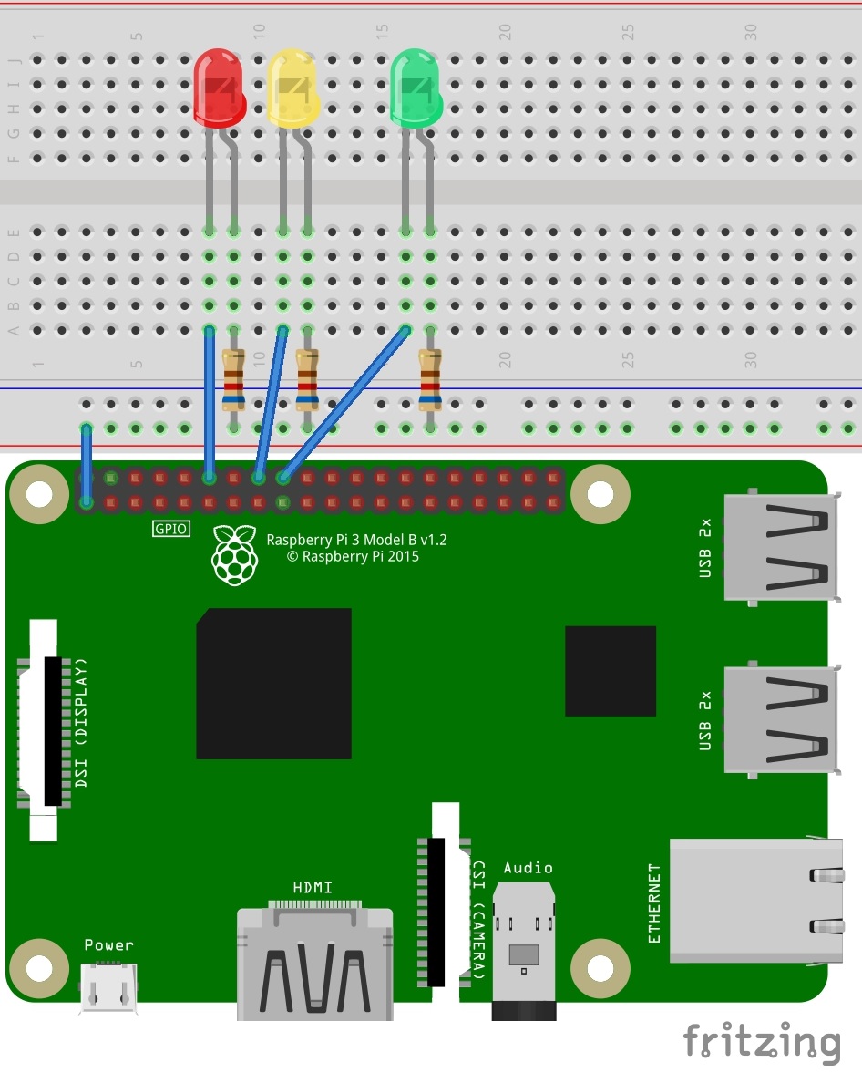
David@urbanus I also note that the wiring diagram for the LED's seems to be incorrect 9or I'm not reading it correctly. Doesnt the pi switch the outputs HIGH when a GPIO pin is called? The diagram seems to feed the LED's from 3.3v and then on through the limiting resistor back to the GPIO which will be at 3.3v when high.
-
@urbanus I also note that the wiring diagram for the LED's seems to be incorrect 9or I'm not reading it correctly. Doesnt the pi switch the outputs HIGH when a GPIO pin is called? The diagram seems to feed the LED's from 3.3v and then on through the limiting resistor back to the GPIO which will be at 3.3v when high.
@urbanus this is the output from the test:
Dec 07 14:56:12 INFO Starting gateway...
Dec 07 14:56:12 INFO Protocol version - 2.3.1
Dec 07 14:56:12 DEBUG MCO:BGN:INIT GW,CP=RNNGL---,REL=255,VER=2.3.1
Dec 07 14:56:12 DEBUG TSF:LRT:OK
Dec 07 14:56:12 DEBUG TSM:INIT
Dec 07 14:56:12 DEBUG TSF:WUR:MS=0
Dec 07 14:56:12 DEBUG TSM:INIT:TSP OK
Dec 07 14:56:12 DEBUG TSM:INIT:GW MODE
Dec 07 14:56:12 DEBUG TSM:READY:ID=0,PAR=0,DIS=0
Dec 07 14:56:12 DEBUG MCO:REG:NOT NEEDED
Dec 07 14:56:12 DEBUG Listening for connections on 0.0.0.0:5003
Dec 07 14:56:12 DEBUG MCO:BGN:STP
Dec 07 14:56:12 DEBUG MCO:BGN:INIT OK,TSP=1
Dec 07 14:56:12 DEBUG TSM:READY:NWD REQ
Dec 07 14:56:12 DEBUG TSF:MSG:SEND,0-0-255-255,s=255,c=3,t=20,pt=0,l=0,sg=0,ft=0,st=OK:
Dec 07 15:02:59 DEBUG TSF:MSG:READ,1-1-255,s=255,c=3,t=7,pt=0,l=0,sg=0:
Dec 07 15:02:59 DEBUG TSF:MSG:BC
Dec 07 15:02:59 DEBUG TSF:MSG:FPAR REQ,ID=1
Dec 07 15:02:59 DEBUG TSF:PNG:SEND,TO=0
Dec 07 15:02:59 DEBUG TSF:CKU:OK
Dec 07 15:02:59 DEBUG TSF:MSG:GWL OK
Dec 07 15:03:00 DEBUG TSF:MSG:SEND,0-0-1-1,s=255,c=3,t=8,pt=1,l=1,sg=0,ft=0,st=OK:0 -
Just in case anybody visits this post with the same problems - It's now sorted and working. Basic issues were:
1 - I did not set the parameters in the MyConfig.h files correctly, especially I needed to uncomment the inclusion feature!
2 - The fritz diagram for the LED 's is incorrect, if you build the gateway with the LED's you need to switch the GPIO pins to ground not to vcc as shown.
RegardsDavid
-
Hi. Hope this link is okay, I'm not really sure how to do this.
https://www.mysensors.org/uploads/57c1a876f40891c215911e40/image/RPi3_status_led.jpg
It shows the GPIO pins routed to pin 1 on the pi - pin 1 is 3.3v. I followed the diagram withoit thinking the first tie and it was only when I had problems I started to think "how does this work"? taking it to ground sorted it.
Thanks
David -
Hi again, I did not select the inverse feature as I was under the impression this just changes their behaviour ( i.e normally illuminated and turned off/on during tx/rx/error or normally not illuminated and turns on/off during tx/rx/error).
Thanks,
David -
Hi again, I did not select the inverse feature as I was under the impression this just changes their behaviour ( i.e normally illuminated and turned off/on during tx/rx/error or normally not illuminated and turns on/off during tx/rx/error).
Thanks,
David@urbanus in your wiring, did you flip around the leds? (i.e. did you connect the longer pin to the gpio pins instead of to vcc?
With your wiring, are the leds on when there is no traffic?
My guess is that you have reversed the connections. Which is fine, but by default the leds will be on.
Hello! It looks like you're interested in this conversation, but you don't have an account yet.
Getting fed up of having to scroll through the same posts each visit? When you register for an account, you'll always come back to exactly where you were before, and choose to be notified of new replies (either via email, or push notification). You'll also be able to save bookmarks and upvote posts to show your appreciation to other community members.
With your input, this post could be even better 💗
Register Login