Gateway device
-
@tbowmo My hat is off to you, for the major effort put forth along with @blacey ,@Anticimex , @axillent and @hek to name but a few.
While following this thread at times lost (mostly?) with explanations and concepts I have been learning which is half the battle.
It seems it never too late for a old dog to learn a little.
However it seems there is a need for a better gw from some of the threads I have read.
I for one will purchase a unit in what ever form it morphs into.Great work with all these boards.
-
A small update here, on an even larger update on the gateway device.
After some considerations, I have decided to switch the MCU for the GW to an atmel SAM D21G, instead of atmega1284. While doing this I have reduced the BOM for the GW, and cut about 1/3 of the BOM price.
The D21G is the same chip that's on the new arduino zero, and also on a kickstarter project called neutrino. @blacey is the one who pointed me in that direction :)
While being a more powerful chip (256kb flash, 32kb ram, 48 MHz, loads of extra peripherals) it is actually cheaper than the atmega1284, and it has build in USB controler, so the ftdi chip could be removed, a couple of other glue components is also gone now.
It will mean that we have to work a bit harder at getting mysensors running, but since the MCU is supported by arduino, we should be able to manage.
-
very interesting! I didn't know neutrino, pretty nice board. Seems there will be some work on software part but it is doable like you said. And you will have more power, which is nice for the GW I think, and I like when chip is usb compatible (like pic18f4550 ...). Maybe one day, it will become HID, lol!
-
I didn't know of the neutrino (or arduino zero) before @blacey mentioned it to me, and he finally got me convinced that I should swap the atmega1284. (I know that @axillent tried to convince me to use another chip, than the atmega, before.. But when you find this, and it can reduce board complexity..)
-
@tbowmo: it is likely same things for me. lots of 8/16bits chip collection (microchip). but never moved to 32bit even if i have a 32bit usb bit wacker (not time to test it). I was thinking that you can do lot of things with 8bit chips. So yesterday, I have read a little the datasheet atsamd21. Wow, 1077 pages! But there is lots lots of features! I think I will try to order one sample for my collection! Plus, these chips seems to be not expensive but there is some learning curve on it. I think Microchip have missed a big move with arduino platform!
-
That right there is a work of art!
-
You may be interested in this Arduino shield:
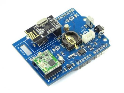
http://www.ebay.com/itm/WireLess-Gate-Shield-DIY-Maker-Seeed-BOOOLE-/171713943896?hash=item27faf2d958It has both NRF24L01+ and RFM69HW radios.
-
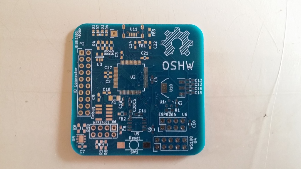
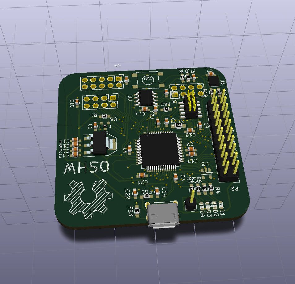
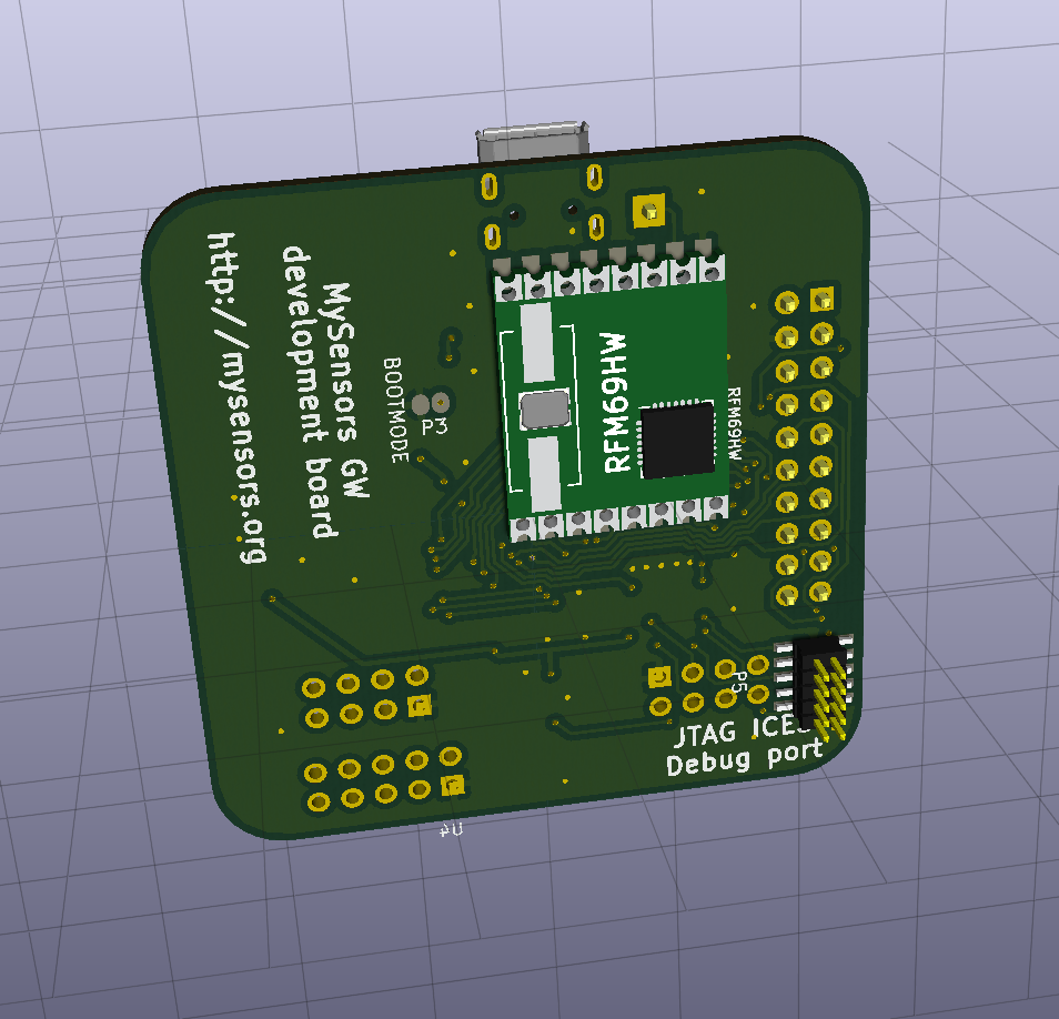
The first pcb's have arrived today.
They came a bit faster from dirtypcbs.com, than I had expected. So haven't even sourced the components yet.
So need to look into that the next couple of days.

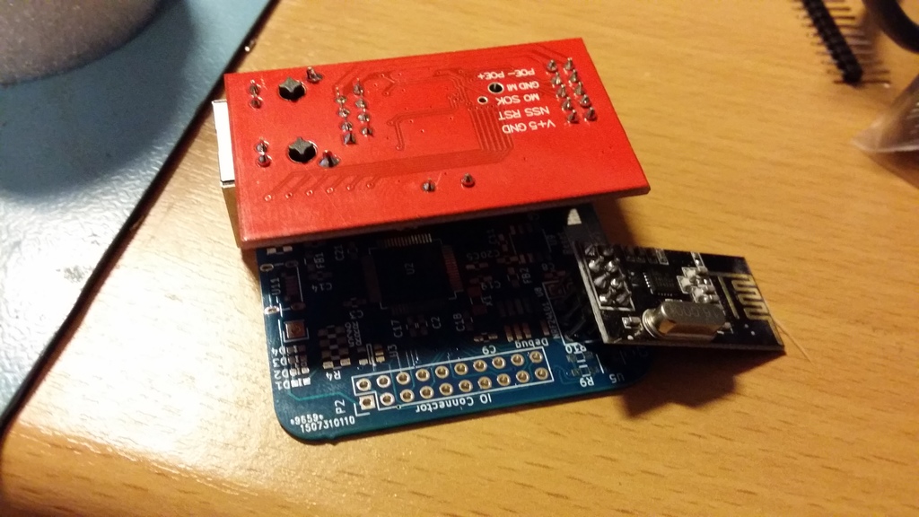
with W5100 / NRF module "mounted" :
-
@ServiceXp
As we need to bring things to life on a new MCU core (Cortex M0), I decided to just make a "simple" dev board, without holes. They will probably be added on the next iteration of the board. (Besides that, 3 of the corners are a bit crammed with components, so no place for the holes anyway.)
-
@tbowmo: very beautiful board. I can't wait to see how it will work. And your feedback about dirtypcb. I often use seeed for their price. But dirty seems good too regarding their shipping rates. I like osh sometimes for their beautiful boards.
-
thx good to know.
-
great :clap:
-
Just learned a lesson the hard way, the last couple of days.. Discovered that I hadn't read the datasheet for the atsamd21 good enough, so I had connected all the PINS for the SPI / UARTs completely wrong. Which means 10-12 connections that was wrong (the board uses 3 SPI ports and 2 UARTs, one SPI doubles as UART, depending on the network interface connected)
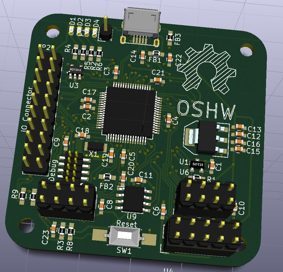
So new boards are in the pipeline from dirtypcbs.com
This is btw improved on a couple of other points, compared to the previous board. Biggest is, that it now has 4 x 3mm mounting holes, (happy now @ServiceXp ? :)). It also got a couple of extra solder jumpers on the backside, that could be used for software configurations, or test points.
-
@tbowmo: what a bad luck! but it is so easy to miss something when you look at the datasheet size :wink:
I hope you will get it working like you want, I am sure :smiley:
I like your enlarged pads for 0402. Is it easier to solder like this? Do you handsolder it? Do you think using 0603/0805 with no enlarged pads would take same place???I am asking this for my future designs, in case. But 0402 is so small...
Hello! It looks like you're interested in this conversation, but you don't have an account yet.
Getting fed up of having to scroll through the same posts each visit? When you register for an account, you'll always come back to exactly where you were before, and choose to be notified of new replies (either via email, or push notification). You'll also be able to save bookmarks and upvote posts to show your appreciation to other community members.
With your input, this post could be even better 💗
Register Login