Gateway device


  • @tbowmo

    re: PoE supply
    http://www.freetronics.com.au/products/power-over-ethernet-regulator-8023af#.VWCsPLmqqko
    is cheap and easy you may be able to piggy back it on the board.
    hope it helps
    phil


  • Admin

    @ServiceXp

    It could be used as serial gateway, there's a ftdi chip onboard. But also place for Ethernet and WiFi connections, together with both nrf24 module and a rfm69 module.

    Made to be as versatile as possible.

    @phil-pritchard

    Ethernet is an add-on module, so a bit hard to implement Poe circuitry on this board. If we could find w5100 module with Poe, it might work.


  • Admin

    Btw. Would it be an idea to include a sensor onboard? (Si7021)


  • Contest Winner

    I see no reason not to (depending on available space) add footprints for various "standard" sensors in addition to a IO header on the board. I have no idea on what impact it has on the sw to have a gateway report sensor values to "itself" but I see no reason for why that could not be supported (if it isn't already).

    End of double-negations 😉


  • Admin

    @Anticimex

    What do you define as "standard" sensors?


  • Contest Winner

    @tbowmo
    Perhaps an unfortunate label. I guess standard footprints would be a better word. I mean footprints for the most commonly used sensor cases. TO-92, DFN and etc. connected such as the typical sensors (1-wire temps and Si7021 like) will "fit".


  • Admin

    @Anticimex

    Problem is that each sensor has its own pinout, so you can't make generic footprints.

    There already is a GPIO header, with 8 pins (4 analog and 4 digital) plus power. So people can make their own daughterboards with sensors. Might convert 2 of them to i2c bus with pull up, and then have si7021 onboard.


  • Have you considered Grove plugs for sensors? This can give flexibility and a large enough number of sensors at a reasonable price.


  • Admin

    @plinioseniore

    Problem is space on the pcb 🙂 as I see it Grove connectors are big and bulky. I have placed a couple of pinheaders (one 8 pin, and one 12 pins) for external devices right now..


  • Contest Winner

    I think a header for daughterboards will go far in terms of flexibility.


  • Admin

    updated the first post in the thread, with links to github project, and pdf of schematics (on github). So it will always point at the latest available one, so I don't have to remember that there is a forum thread to keep updated 🙂


  • Contest Winner

    Nice nice. I am very interested in this as I have more or less decided to swap to RF69 from RF24. Both for range and because I like the concept of having the radio handle the encryption on my signed packets (yep, I am paranoid as hell). Unfortunately, it means my current gateway has to go but I have made a "sensor evaluation board" (got the PCBs, still waiting for components). Once I get the components and can verify all the features I put on it I will publish it in this forum for those interested. It will still rely on Arduino modules and such so it is not the hard-core approach like the Sensebender Micro though.


  • Contest Winner

    @tbowmo
    I believe you previously had the interrupt for RF69 connected. But it does not seem to be anymore. Any particular reason for skipping that?


  • Admin

    @Anticimex

    I'm still rearranging things in the schematics, in order to get the best board layout :).

    Could we go with one combined irq for both radio modules? (rfm69/Nrf24)?

    / Thomas


  • Contest Winner

    I see no reason why that would not work. I sure hope so as I did that on my board 🙂
    Both radios will never be connected (or at least in use) simultaneously so it should be ok.


  • Admin

    @Anticimex

    could be someone got brainfreeze and decided to go with both radios at once in one setup.. On the other hand, we're not using IRQ for the nrf24 at the moment..


  • Contest Winner

    @tbowmo
    Even so, the electrical properties of the interrupt outputs on the module should ensure no meltdown occurs. And I think the user would get bigger problems than just having to figure out the origin of the interrupt 🙂


  • Contest Winner

    On the other hand, is there a usecase to provide HW interrupt functionality for a dagughterboard on the gateway? Since it will "by definition" have a solid power supply, any sensors using interrupts should be fine with the soft-interrupt options (have not looked into those myself though) or simply use polling. Power saving makes little sense in this case. The radios are probably better off with "real" interrupts (if we ever use them).


  • Admin

    been fiddling with layout, and schematics changes..

    Added a couple of MAX3002E for level conversion between 5V and 3V3 domains on the board. (Links to the schematic are in the first post of this thread)

    MysensorsGW.png

    Waiting for samples of the ESP8266, and W5100 modules, so I can make some last measurements before ordering boards.


  • Hi,

    just want to share with you some of our progress in a board similar to the one that you are designing.

    This is based on Atmega32U4 and has socket for nRF24L01 and ESP8266 and is designed to be battery operated and support Grove connector. The board has mosfet to switch off the sensor while sleeping and keep low the consumption, this should stand a year on battery.

    We just received the PCB, picture at the link below,
    http://www.souliss.net/2015/06/sensor-battery-board-pcb-arrived.html

    The schematic and layout are open-source and hope that this board may fit some needs also in the MySensor community
    https://github.com/souliss/boards/tree/master/Battery_Operated_Board/Ver1

    Regards,
    Dario.


  • Admin

    @plinioseniore

    Looks like a nice board you have created... Only problem is, that we run out of memory on atmega328, if we want to run with signing and have MQTT client on board.

    So that is why we have bumped the processor to a atmega1284 instead, having 4 times the memory, than atmega328. Also, with this board, we have the posibility to use both RFM69 and NRF24L01 on the sensor network..


  • Admin

    Tried to make a concept drawing, of NRF module placement

    MysensorsGW-2.png

    the esp8266 is placed in a similar way, on the right edge of the board, also hanging over the edge with the antenna part.

    the W5100 board (which is similar to this one from itead studio) is turned 180 degrees, which makes the ethernet jack placement above the large "empty" space on the board (there is a 2x3 pinheader in the concept drawing)

    The micro usb connector will be just beside the ethernet jack. between the ether jack, and the single pinheader pin (this is the antenna connection point for the rfm69 you can put on the bottom of the board)

    Things are still a bit conceptual, trying to visualize it for my self 🙂


  • I'll second (third? fourth? whatever...) the suggestion to design this to fit a cheap and readily available enclosure. Something like:

    http://www.aliexpress.com/item/Free-Shipping-Plastic-Waterproof-Clear-Cover-Electronic-Project-Box-Enclosure-Case-85-58-33MM/2025247551.html

    (Not saying that's ideal; just an example.)


  • Admin

    @rickmontana83

    the board is 50x50 mm, and with the radio / wifi protruding over the edge, this box should fit nicely.

    The reason why I chose 50x50mm for the board size, is that it's either 50x50mm, or 100x100mm board when we order prototypes, which is more expensive. (And I like to make things small :))


  • Agree about smaller. Everything looks classier with less wasted space.

    Probably too late now, but if the board had mounting holes that lined up with the enclosure that would be sweet. I'm always at a loss for how to keep my boards stable inside their plastic homes. Would love to hear peoples' solutions for mounting when the holes don't line up.


  • Admin

    @rickmontana83

    nothing's too late (yet). I haven't even ordered the first prototype batch yet. Still ironing out some details, and routing the PCB (I have only scratched the routing for the 10th time or so :s ). Actually I had thought about adding a couple of mounting holes in the board..

    I'll see if the boxes that I have, resembles the one that I just linked to.. (I've talked with @hek about finding some enclosures a couple of days ago, when we suddenly found a seller on ali express, that only had enclosures of various kinds).


  • @tbowmo

    Yes the Atmega32U4 and Atmega328 has in the RAM their main problem, in our case we run smoothly in the 2KBytes available because we don't use ASCII in the protocol, but binary only.

    Then the board is for as a remote sensor node, running on battery, not a main gateway board.

    In any case, the board that you are designing will work nicely also with Souliss.battery_board-1.jpg


  • Hero Member

    @tbowmo Mounting holes would be very good. 😳


  • Admin

    ok now with mounting holes. Or sort of.. the holes are 4.8cm apart, center to center, and the pcb is 5cm wide. I have used this case as a template.

    MysensorsGW.png


  • Admin

    and now with a w5100 module attached

    MysensorsGW-w5100.png


  • Hardware Contributor

    very nice board, bravo !
    thank you for sharing your work and knowledge.


  • Admin

    Sweet!!! 👍 👍 👍

    Sign me up for 5! 🙂


  • You put a work into this board and it looks great. Cannot wait for it to come available.


  • @tbowmo My hat is off to you, for the major effort put forth along with @blacey ,@Anticimex , @axillent and @hek to name but a few.

    While following this thread at times lost (mostly?) with explanations and concepts I have been learning which is half the battle.

    It seems it never too late for a old dog to learn a little.

    However it seems there is a need for a better gw from some of the threads I have read.
    I for one will purchase a unit in what ever form it morphs into.

    Great work with all these boards.


  • Admin

    I'm still routing the board, it's more complicated than my previous boards, so will be a bit longer process to get all in place.


  • Admin

    A small update here, on an even larger update on the gateway device.

    After some considerations, I have decided to switch the MCU for the GW to an atmel SAM D21G, instead of atmega1284. While doing this I have reduced the BOM for the GW, and cut about 1/3 of the BOM price.

    The D21G is the same chip that's on the new arduino zero, and also on a kickstarter project called neutrino. @blacey is the one who pointed me in that direction 🙂

    While being a more powerful chip (256kb flash, 32kb ram, 48 MHz, loads of extra peripherals) it is actually cheaper than the atmega1284, and it has build in USB controler, so the ftdi chip could be removed, a couple of other glue components is also gone now.

    It will mean that we have to work a bit harder at getting mysensors running, but since the MCU is supported by arduino, we should be able to manage.


  • Hardware Contributor

    very interesting! I didn't know neutrino, pretty nice board. Seems there will be some work on software part but it is doable like you said. And you will have more power, which is nice for the GW I think, and I like when chip is usb compatible (like pic18f4550 ...). Maybe one day, it will become HID, lol!


  • Admin

    @scalz

    I didn't know of the neutrino (or arduino zero) before @blacey mentioned it to me, and he finally got me convinced that I should swap the atmega1284. (I know that @axillent tried to convince me to use another chip, than the atmega, before.. But when you find this, and it can reduce board complexity..)


  • Hardware Contributor

    @tbowmo: it is likely same things for me. lots of 8/16bits chip collection (microchip). but never moved to 32bit even if i have a 32bit usb bit wacker (not time to test it). I was thinking that you can do lot of things with 8bit chips. So yesterday, I have read a little the datasheet atsamd21. Wow, 1077 pages! But there is lots lots of features! I think I will try to order one sample for my collection! Plus, these chips seems to be not expensive but there is some learning curve on it. I think Microchip have missed a big move with arduino platform!


  • Admin

    A couple of late night shots, of the progress..

    Getting ready for the first prototype spin of the board

    MysensorsGW-no-radios.png

    MysensorsGW-bottom.png


  • Hero Member

    That right there is a work of art!


  • Hero Member

    You may be interested in this Arduino shield:
    gw.JPG
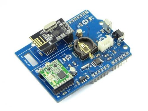
    http://www.ebay.com/itm/WireLess-Gate-Shield-DIY-Maker-Seeed-BOOOLE-/171713943896?hash=item27faf2d958

    It has both NRF24L01+ and RFM69HW radios.


  • @tbowmo this gw is looking good, hope the prototypes get to you soon!


  • Admin

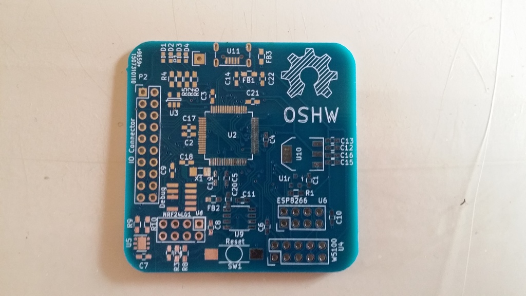
    The first pcb's have arrived today.

    They came a bit faster from dirtypcbs.com, than I had expected. So haven't even sourced the components yet.

    So need to look into that the next couple of days.

    front.jpg

    back.jpg

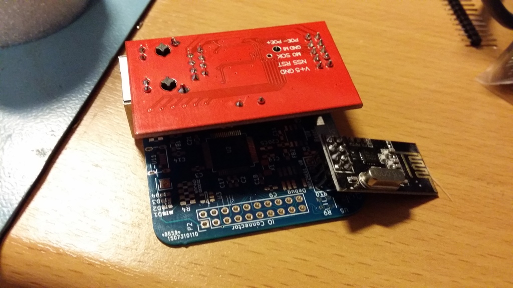
    with W5100 / NRF module "mounted" :
    mockup.jpg


  • Hero Member

    @tbowmo No mounting holes?


  • Admin

    @ServiceXp

    As we need to bring things to life on a new MCU core (Cortex M0), I decided to just make a "simple" dev board, without holes. They will probably be added on the next iteration of the board. (Besides that, 3 of the corners are a bit crammed with components, so no place for the holes anyway.)


  • Hardware Contributor

    @tbowmo: very beautiful board. I can't wait to see how it will work. And your feedback about dirtypcb. I often use seeed for their price. But dirty seems good too regarding their shipping rates. I like osh sometimes for their beautiful boards.


  • Admin

    @scalz

    Haven't tried any of the other "cheap" board houses. But I'm glad for the quality that dirtypcbs are delivering, and the price can't be argued about..


  • Hardware Contributor

    thx good to know.


  • Admin

    things are beginning to take form..

    First arduino sketch are running on the GW

    Proof is here 🙂


  • Hardware Contributor

    great 👏


  • Admin

    Just learned a lesson the hard way, the last couple of days.. Discovered that I hadn't read the datasheet for the atsamd21 good enough, so I had connected all the PINS for the SPI / UARTs completely wrong. Which means 10-12 connections that was wrong (the board uses 3 SPI ports and 2 UARTs, one SPI doubles as UART, depending on the network interface connected)

    So new boards are in the pipeline from dirtypcbs.com

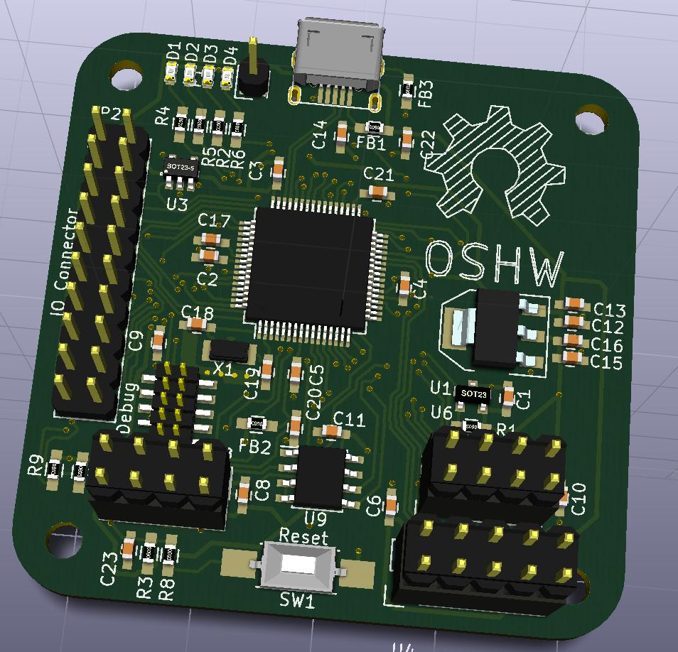
    This is btw improved on a couple of other points, compared to the previous board. Biggest is, that it now has 4 x 3mm mounting holes, (happy now @ServiceXp ? :)). It also got a couple of extra solder jumpers on the backside, that could be used for software configurations, or test points.

    MysensorsGW.jpg


  • Hardware Contributor

    @tbowmo: what a bad luck! but it is so easy to miss something when you look at the datasheet size 😉
    I hope you will get it working like you want, I am sure 😃
    I like your enlarged pads for 0402. Is it easier to solder like this? Do you handsolder it? Do you think using 0603/0805 with no enlarged pads would take same place???I am asking this for my future designs, in case. But 0402 is so small...


  • Admin

    @scalz

    I'm using 0603 components this time, as I'm not under that big a space constraint, as on the sensebender micro.

    The biggest issue is the finepitched SAMD21, have to be extra careful not to make solder bridges between the pins..


  • Hardware Contributor

    @tbowmo: 0603, cool. I have some samd21 sample but have not tried to solder them. it looks tiny but I think I will be able but not without some 😰
    thank you for your precision 😄


  • Admin

    @scalz

    atsamd21 comes in 3 variants, with 32, 48 og 64 pins (If I remember right). I'm using the 64 pin variant

    If things go well with this one, then I might make a sensebender micro 2, with an 32 pin atsamd20 (almost the same as d21, but without USB host/slave capabilities)


  • Hardware Contributor

    @tbowmo: oh, i have the 48p variant. so I will try to use it in another project in the future. and will order other sample.
    sensebender micro2 atsam, wow, crazy thing! could be fun to see this 😄


  • Hero Member

    @tbowmo Now that's what I'm talking about.. Those holes look so sexy.... wait, that doesn't sound right.... :bowtie:


  • Hero Member

    @tbowmo How is the testing going?


  • Admin

    @ServiceXp

    I just received the PCBs for the second prototype spin yesterday, the first spin had too many errors in the routing around SPI / UARTS so I decided to ditch it, and do a second spin. Dirtypcbs got some hickups processing my gerbers but finaly made the boards.

    I hope that I can get around to assemble one this weekend, but I can't promise anything, as I have been loaded more than 150% with work (both from my employer, and from the wife).


  • Hero Member

    @tbowmo Sounds Good, Thanks for the update.


  • Admin

    Images of the latest pcb's (Before SMD assembly)

    Unfortunately I "injured" my back today (aah, maybe not injured, but feels like it :() so I'm on strong medics to keep the pain away. That means that didn't get around to do the SMD assembly today as I planned, as I can't sit at the desk for a longer time.. hope that it gets better during the weekend.

    front.jpg
    back.jpg


  • Hero Member

    @tbowmo Oh now that is sexy.. From someone with back problems, you take it easy for the next 3 days Sir!! 👈


  • Admin

    Aahh.. I'm back in the man-cave. Been too long since I had a chance to power up the soldering irons..

    Anyways, I've mounted the first of the second prototype spin, so next up is getting firmware written, and tested..

    board.jpg


  • Hardware Contributor

    @tbowmo: it looks very nice. I like the way you place components. I think I need to look more at your design and learn 😉
    With a firmware, it looks promising 😃


  • Admin

    @scalz

    Thanks 🙂 I hope that I at least can get some LED's flashing tonight :). And then perhaps the bootloader programmed.

    / Thomas


  • Admin


  • Hardware Contributor

    yeah 😄


  • Admin

    A small update before I hit the bed tonight..

    I've got radio up and running on the SAMD, and got the first message from one of my sensebender micros through to my pc.

    It's still in debug mode, using a serial port on the samd as output (And my logic analyzer to decode the serial stream). So no ethernet / wifi or the like up yet.

    The next step will be to have it use USB instead of the serial port..

    debug-setup.jpg


  • Contest Winner

    👍 good work!


  • Hardware Contributor

    Great! I will buy one of these as soon as this is working as you want 🙂


  • Wow - excellent! I'd buy one


  • Admin

    a new small update..

    Got it working as a serial GW.. Receiving the first messages from one of my sensebenders..

    Also got the ethernet going, this is not integrated with the mysensors parts though, as I have to refactor nrf / ethernet libraries a bit, in order to support multiple (HW) SPI interfaces..


  • Hardware Contributor

    @tbowmo said:

    Got it working as a serial GW.. Receiving the first messages from one of my sensebenders..

    Also got the ethernet going, this is not integrated with the mysensors parts though, as I have to refactor nrf / ethernet libraries a bit, in order to support multiple (HW) SPI interfaces..

    Sounds great. I'm definitely interested in using this as a gateway as well. Any chance you're going to add SPI transaction support to those libraries (more info in my post here)? I know there are RFM library versions that have that as well (see here).


  • Admin

    @TD22057

    Here is more hw spi ports available on this beauty. So radio and ethernet is separated on their own spi bus. There is a 3rd spi bus available on the MYSX connector, that is at free disposal to the end user.


  • Hardware Contributor

    Nice - I forgot that you upgraded and weren't using a 328 processor.


  • Admin

    A small Christmas progress update.

    I got external eeprom, and w5100 module running now.

    That means I have a working ethernet GW running with nrf24 running on SAMD.

    I'm waiting for rfm69 modules from China before I can verify that this part also works as expected.

    An ethernet GW with hw signing is using 35.988 bytes, or 13% of the available flash size, which is 256kbyte. So we have "plenty" of room to do other fun stuff on the GW


  • Admin

    I have updated the original posting, with updated hardware details.

    • Removed the ESP8266 from the feature list (It's supporting the mysensors library native).
    • Removed onboard SPI flash, but will probably add sdcard / micro sdcard reader
    • Might add battery backup for an onboard RTC.. (the SAMD have an onboard RTC, only using 2-3uA in low power RTC keep alive mode)

  • Hardware Contributor

    @tbowmo: I love your project , I can't wait to try your awesome baby GW 😄
    I agree with you with your updates too. RTC could be interesting.
    Humm, when I see price and memory, I am very tempted to update one of my sensors board with atsamL21 family to give a try...do you have an advice for a good&cheap jtag programmer???


  • Admin

    @scalz

    I'm using an atmel jtagice3, with a custom PCB for converting from jtagice3 pinouts to standard cortex m0 debug connector. (have plans on selling this converter board elsewhere sometime in the future)

    I got the jtagice3 5 years ago as a gift from atmel, for attending a course on their xmega series of MCU's. Don't know of any cheaper alternatives out there


  • Hardware Contributor

    Hi. How far from finished is this gw? It looks awesome. My is acting fishy and I need to order a new one. I can wait some for this if you have some sort of eta.


  • Hardware Contributor

    oki, thx 😃 I see for connectors..I will look if I can find a cheaper "working" alternative for atsam...


  • Admin

    @sundberg84

    My best guess is that this will probably be end Q1 2016, as I have to verify RFM69, and probably have a second look at some kind of battery backup for RTC, and sdcard reader. (I have a sdcard reader breakout board, so I should be able to verify that part relatively quickly)

    We have also discussed this briefly in the "core team" we would like to have the next revision of the library out first, because support for the GW is only in development branch at the moment. So to minimize confusion on what branch to use for the board, we would like to have an official release that supports the board.


  • Hardware Contributor

    @tbowmo Ok thanks for a quick reply - looking forward to your gw! I will buy me a new gateway from ebay to secure my HA, but when you needs beta tester let me know as i already use dev.


  • Admin

    @sundberg84

    I know that things are not progressing as fast with the GW. There have been some non mysensors bumps on the road, and I still have some to overcome.

    If it wasn't for that daytime job, that takes up too much of the precious spare time that could be used for fun hobbies like mysensors, it would have been finished a long time ago 🙂


  • Hardware Contributor

    Didnt mean to rush @tbowmo - it looked so good at the pictures so I thought it was ready soon!And yea... that thing called daytime job takes way to much time 🙂


  • Admin

    New comments should be in the thread over in the open hardware section here


Log in to reply
 

Suggested Topics

  • 87
  • 3
  • 6
  • 2
  • 8
  • 5

19
Online

11.2k
Users

11.1k
Topics

112.5k
Posts