Skip to content
  • MySensors
  • OpenHardware.io
  • Categories
  • Recent
  • Tags
  • Popular
Skins
  • Light
  • Brite
  • Cerulean
  • Cosmo
  • Flatly
  • Journal
  • Litera
  • Lumen
  • Lux
  • Materia
  • Minty
  • Morph
  • Pulse
  • Sandstone
  • Simplex
  • Sketchy
  • Spacelab
  • United
  • Yeti
  • Zephyr
  • Dark
  • Cyborg
  • Darkly
  • Quartz
  • Slate
  • Solar
  • Superhero
  • Vapor

  • Default (No Skin)
  • No Skin
Collapse
Brand Logo
  1. Home
  2. Hardware
  3. PCB design and production

PCB design and production

Scheduled Pinned Locked Moved Hardware
pcbproductiondesign
17 Posts 8 Posters 7.6k Views 2 Watching
  • Oldest to Newest
  • Newest to Oldest
  • Most Votes
Reply
  • Reply as topic
Log in to reply
This topic has been deleted. Only users with topic management privileges can see it.
  • jendrushJ jendrush

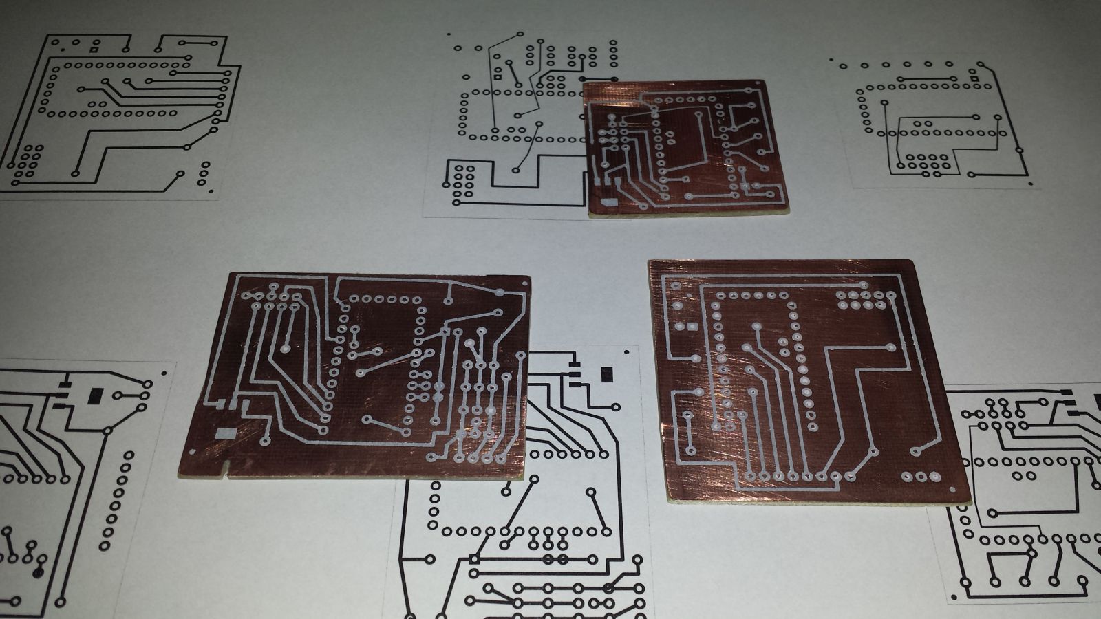
    My new pcb's. Smallest for room light, to fit behind wall switch. Second(left) is for kitchen - 3 ds18b20(kitchen temp, fridge temp, and freezer temp), motion sensor, 1602 display, and 2 contact switches for fridge door. Last is for nokia 5110 display, and motion sensor. I can display anything i want on this node. 20140815_195808.jpg
    marceltrapmanM Offline
    marceltrapmanM Offline
    marceltrapman
    Mod
    wrote on last edited by
    #6

    @jendrush said:

    My new pcb's.

    I noticed that you do top and bottom layer also on connectors.
    How do you solder that?

    I have read a lot about creating your own pcb's and all seem to suggest to use via's...

    Fulltime Servoy Developer
    Parttime Moderator MySensors board

    I use Domoticz as controller for Z-Wave and MySensors (previously Indigo and OpenHAB).
    I have a FABtotum to print cases.

    jendrushJ 1 Reply Last reply
    0
    • marceltrapmanM marceltrapman

      @jendrush said:

      My new pcb's.

      I noticed that you do top and bottom layer also on connectors.
      How do you solder that?

      I have read a lot about creating your own pcb's and all seem to suggest to use via's...

      jendrushJ Offline
      jendrushJ Offline
      jendrush
      wrote on last edited by
      #7

      @marceltrapman said:

      I noticed that you do top and bottom layer also on connectors.
      How do you solder that?

      I have read a lot about creating your own pcb's and all seem to suggest to use via's...

      I am using VIA too. Only this board for 5110 display have soldering points on both sides becouse display is connected on the one side, rest on the other. Normally all soldering points have to be on one side.

      1 Reply Last reply
      0
      • jendrushJ jendrush

        I do not remember who started this topic. But this time i will start. Those are my photos from custom PCB production https://www.dropbox.com/sh/ec4ap8dgci1oe0p/AAD3YIqS_JqKMiUFu9TAfF5Ca . This is my second PCB, first was made 12 years ago for school project. I've made few mistakes, but next board will be much much better.

        ferpandoF Offline
        ferpandoF Offline
        ferpando
        Hero Member
        wrote on last edited by ferpando
        #8

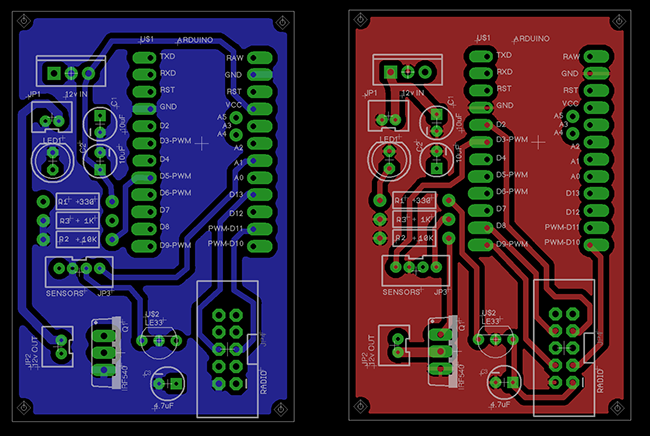
        Here is my first attemp at it.
        I just started with eagle, so maybe there is room for improvement.
        This is for a dimmer node, with some connector for motion detector and light sensor.
        It has an onboard 7805 regulator and a mosfet to PWM the leds.
        mynode.png

        Comments are welcome

        jendrushJ DammeD 2 Replies Last reply
        2
        • ferpandoF ferpando

          Here is my first attemp at it.
          I just started with eagle, so maybe there is room for improvement.
          This is for a dimmer node, with some connector for motion detector and light sensor.
          It has an onboard 7805 regulator and a mosfet to PWM the leds.

          mynode.png

          Comments are welcome

          jendrushJ Offline
          jendrushJ Offline
          jendrush
          wrote on last edited by
          #9

          @ferpando Your's PCB looks more pro than mine:) But designing pcb for home etching is little harder becouse there is no easy way to make double sided soldering points, so every soldering point must be at one side of pcb.

          ferpandoF 1 Reply Last reply
          0
          • ferpandoF ferpando

            Here is my first attemp at it.
            I just started with eagle, so maybe there is room for improvement.
            This is for a dimmer node, with some connector for motion detector and light sensor.
            It has an onboard 7805 regulator and a mosfet to PWM the leds.

            mynode.png

            Comments are welcome

            DammeD Offline
            DammeD Offline
            Damme
            Code Contributor
            wrote on last edited by
            #10

            @ferpando I would run reset to one of your unused pins at the radio and you have a custom ISP connector.

            ferpandoF 1 Reply Last reply
            0
            • jendrushJ jendrush

              @ferpando Your's PCB looks more pro than mine:) But designing pcb for home etching is little harder becouse there is no easy way to make double sided soldering points, so every soldering point must be at one side of pcb.

              ferpandoF Offline
              ferpandoF Offline
              ferpando
              Hero Member
              wrote on last edited by
              #11

              @jendrush
              I don't think soldering on both sides would be a problem.
              You just need to have a little more room.
              I'll post pictures of the finished board.

              1 Reply Last reply
              0
              • DammeD Damme

                @ferpando I would run reset to one of your unused pins at the radio and you have a custom ISP connector.

                ferpandoF Offline
                ferpandoF Offline
                ferpando
                Hero Member
                wrote on last edited by
                #12

                @Damme
                Yes that would be nice to have :-)
                I'll implement it on the next iteration

                1 Reply Last reply
                0
                • V Offline
                  V Offline
                  Vodden
                  wrote on last edited by
                  #13

                  @ferpando

                  Did you ever produce the board that you have pictured above for the dimmable LED's?

                  Did it work?

                  I would be interested in getting 7-10 of these for 12V LED cable lighting applications that I currently have in my home that cannot be supported by conventional Z-Wave dimmers due to the lights being fed from a 120VAC to 12VDC converter. I have made one on a prototype PCB but it is still slightly large for the enclosure and the one you pictured appears that it would fit tidily in the enclosures.

                  Thx

                  Vodden

                  M 1 Reply Last reply
                  0
                  • V Vodden

                    @ferpando

                    Did you ever produce the board that you have pictured above for the dimmable LED's?

                    Did it work?

                    I would be interested in getting 7-10 of these for 12V LED cable lighting applications that I currently have in my home that cannot be supported by conventional Z-Wave dimmers due to the lights being fed from a 120VAC to 12VDC converter. I have made one on a prototype PCB but it is still slightly large for the enclosure and the one you pictured appears that it would fit tidily in the enclosures.

                    Thx

                    Vodden

                    M Offline
                    M Offline
                    Mrlynx
                    Hardware Contributor
                    wrote on last edited by
                    #14

                    @Vodden how large is your enclosure?
                    I am working on a daughterboard for my mys1.1 with 4 channels of pwm and current measuring on each channel.
                    each board is 50x50 mm stacked on top of each other.

                    http://www.sa2avr.se

                    V 1 Reply Last reply
                    1
                    • M Mrlynx

                      @Vodden how large is your enclosure?
                      I am working on a daughterboard for my mys1.1 with 4 channels of pwm and current measuring on each channel.
                      each board is 50x50 mm stacked on top of each other.

                      V Offline
                      V Offline
                      Vodden
                      wrote on last edited by Vodden
                      #15

                      @Mrlynx

                      I'm unsure if this solution would work or not. What I am working with is an IKEA Termosfar enclosure. There is very limited room inside and I think that the solution you have proposed wouldn't likely fit.

                      The prototype board is VERY tight mostly due to the thickness with the pin header installed. The outside dimensions are also critical, with the smallest possible prototype board just barely able to fit. I think the pictured PCB would work perfectly and I have all the parts to build it.

                      @rosskinard was working on a version of these boards as well but had some issues with the pinout, but I have not heard of any progress on it or if they are available. I was hoping that these ones were available so I could get these lights on dimmers.

                      1 Reply Last reply
                      0
                      • ferpandoF Offline
                        ferpandoF Offline
                        ferpando
                        Hero Member
                        wrote on last edited by
                        #16

                        Hello,

                        I've been really busy with work and havn't had the time to do some proper testing.
                        I did assemble a home made board and hope to do some tests soon.
                        Here's how it looks like:

                        IMG_7931.JPG IMG_7930.JPG IMG_7929.JPG

                        I'll keep you posted

                        1 Reply Last reply
                        0
                        • V Offline
                          V Offline
                          Vodden
                          wrote on last edited by
                          #17

                          @ferpando
                          @rosskinard

                          Has anyone made any headway on this project?

                          1 Reply Last reply
                          1
                          Reply
                          • Reply as topic
                          Log in to reply
                          • Oldest to Newest
                          • Newest to Oldest
                          • Most Votes


                          30

                          Online

                          11.7k

                          Users

                          11.2k

                          Topics

                          113.1k

                          Posts


                          Copyright 2025 TBD   |   Forum Guidelines   |   Privacy Policy   |   Terms of Service
                          • Login

                          • Don't have an account? Register

                          • Login or register to search.
                          • First post
                            Last post
                          0
                          • MySensors
                          • OpenHardware.io
                          • Categories
                          • Recent
                          • Tags
                          • Popular