Parking Sensor
-
@hek Received my LED ring in the mail over the weekend. Hooked it up and ran your code. Everything looks to be working great, including the timeout code. Now need to mount and test under real world conditions, i.e,. in the garage with the car. Has anyone done that yet?
-
@hek Received my LED ring in the mail over the weekend. Hooked it up and ran your code. Everything looks to be working great, including the timeout code. Now need to mount and test under real world conditions, i.e,. in the garage with the car. Has anyone done that yet?
@Dan-S. said:
Has anyone done that yet?
Not yet, but I've got plans, big plans :) - I'm working on a leak detector now but when that board is done, I'm going to build an "ultimate garage" PCB that will have the the parking LED, distance sensor, temp/humidity, garage door location sensors, garage door open/close relay, and will automatically close the garage door after a timeout unless a button is pressed.
Here's the way I think about the parking problem: the car moves through 3 different areas: 1) entering garage (not safe), 2) safe to park (far enough in, but not too far), 3) danger - too far. But how do you know what sensor values those correspond to? Especially since mounting the sensor in different areas, at different angles, and with different vehicles will change those values. So if you hold down a button on the sensor, it puts it into config mode. Move the car to the start of the safe area, and push the button to record that sensor reading. Then move the car to the end of the safe parking area and push the button again to record that sensor reading. Then have the software dynamically update the LED ranges to respond to those sensors. Something like: in area 1), illuminate more and more LED's as the car moves through the area. When the car hits area 2), flash the ring green 3 times, then fully illuminate all LED's in green. As the car moves through area 2), decrease the number of LED's illuminated until it hits area 3) where all the LED's flash red.
-
@hek Received my LED ring in the mail over the weekend. Hooked it up and ran your code. Everything looks to be working great, including the timeout code. Now need to mount and test under real world conditions, i.e,. in the garage with the car. Has anyone done that yet?
@Dan-S. Would you mind providing a little detail on your build? I'm totally new and having problems trying to figure out a few things
Do I need a capacitor? If so will 22uf do and where do I hook it up.
I really just looking for a few detailed pics so I can hook things up correctly
Thanks
-
My brother just bought a house and I am going to sucker him into taking up this project by building this for him. I want to add some gas sensors and would like advice on best ones to add. I want to monitor CO, LPG, Butane, and fumes you would get off regular old automotive gas.
-
@Dan-S. Would you mind providing a little detail on your build? I'm totally new and having problems trying to figure out a few things
Do I need a capacitor? If so will 22uf do and where do I hook it up.
I really just looking for a few detailed pics so I can hook things up correctly
Thanks
-
@Dan-S. Would you mind providing a little detail on your build? I'm totally new and having problems trying to figure out a few things
Do I need a capacitor? If so will 22uf do and where do I hook it up.
I really just looking for a few detailed pics so I can hook things up correctly
Thanks
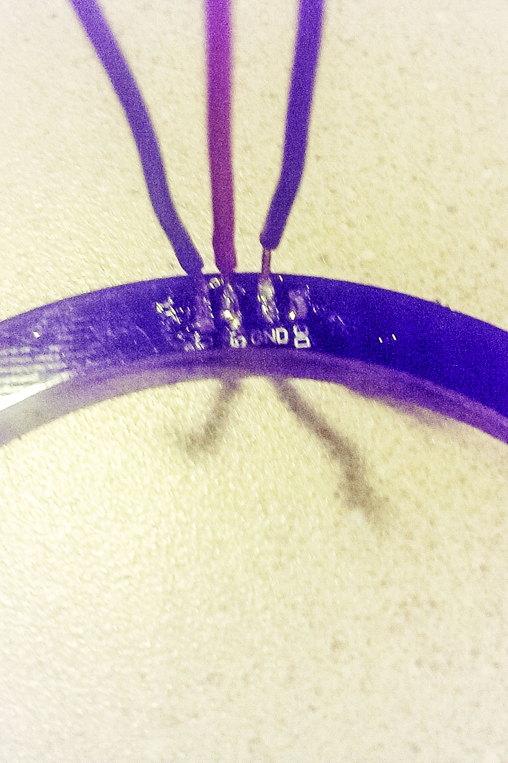
@chilump I am moving from the prototype setup to the garage setup. The first picture shows the LED ring connections. I used solid copper wire because it facilitated what I wanted to do. I squeezed the ends of the wire to flatten them and bent them 90 degrees to make it a bit easier to solder to the solder pads on the led ring. The pads are marked D1,5V,GND and D0. D0 is not used in this application. These are the most difficult connections to make.
 ```
```
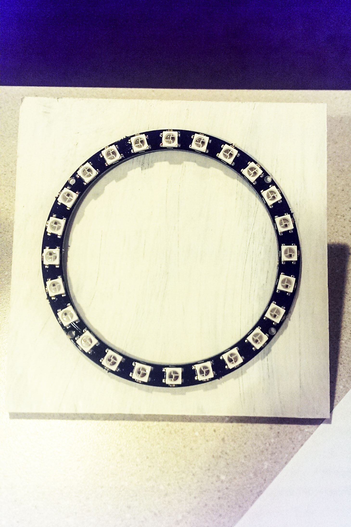
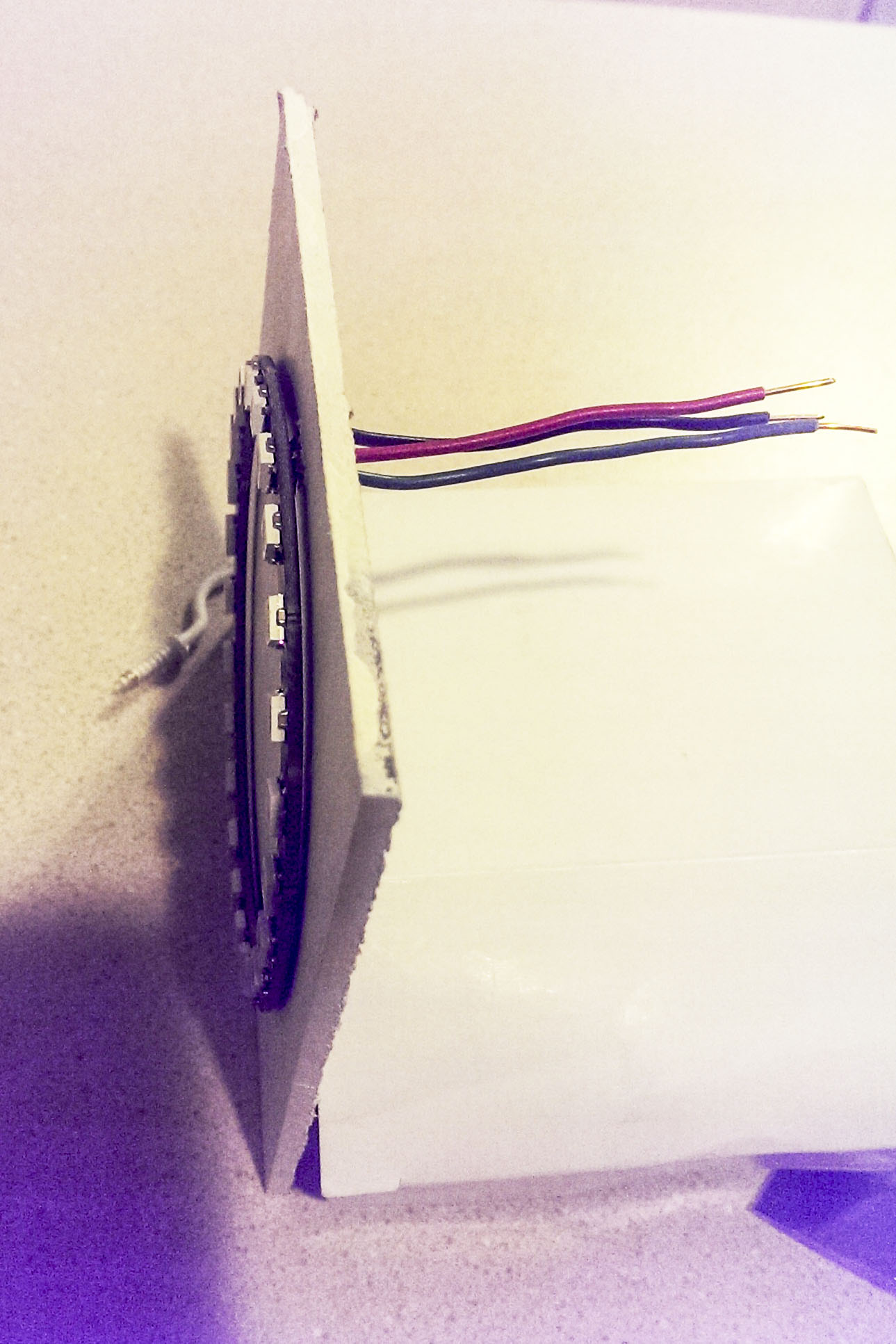
I mounted the ring on a square piece of 1/4 in particle board, drilling holes to feed the wires through. It only has a primer coat on it in the picture.
I will connect a 100uf between the 5v and ground connectors behind the board so it cannot be seen and then mount it on the garage wall.
Hek's 22uf recommendation is probably good enough, but in reading about led ring applications an the internet 100uf was recommended for Adafruit neopixel rings. How much you need is dependent on the led intensity and how rapidly the signal will be changing--for this case 22uf should be ok.I put the distance sensor in one of the standard cases.
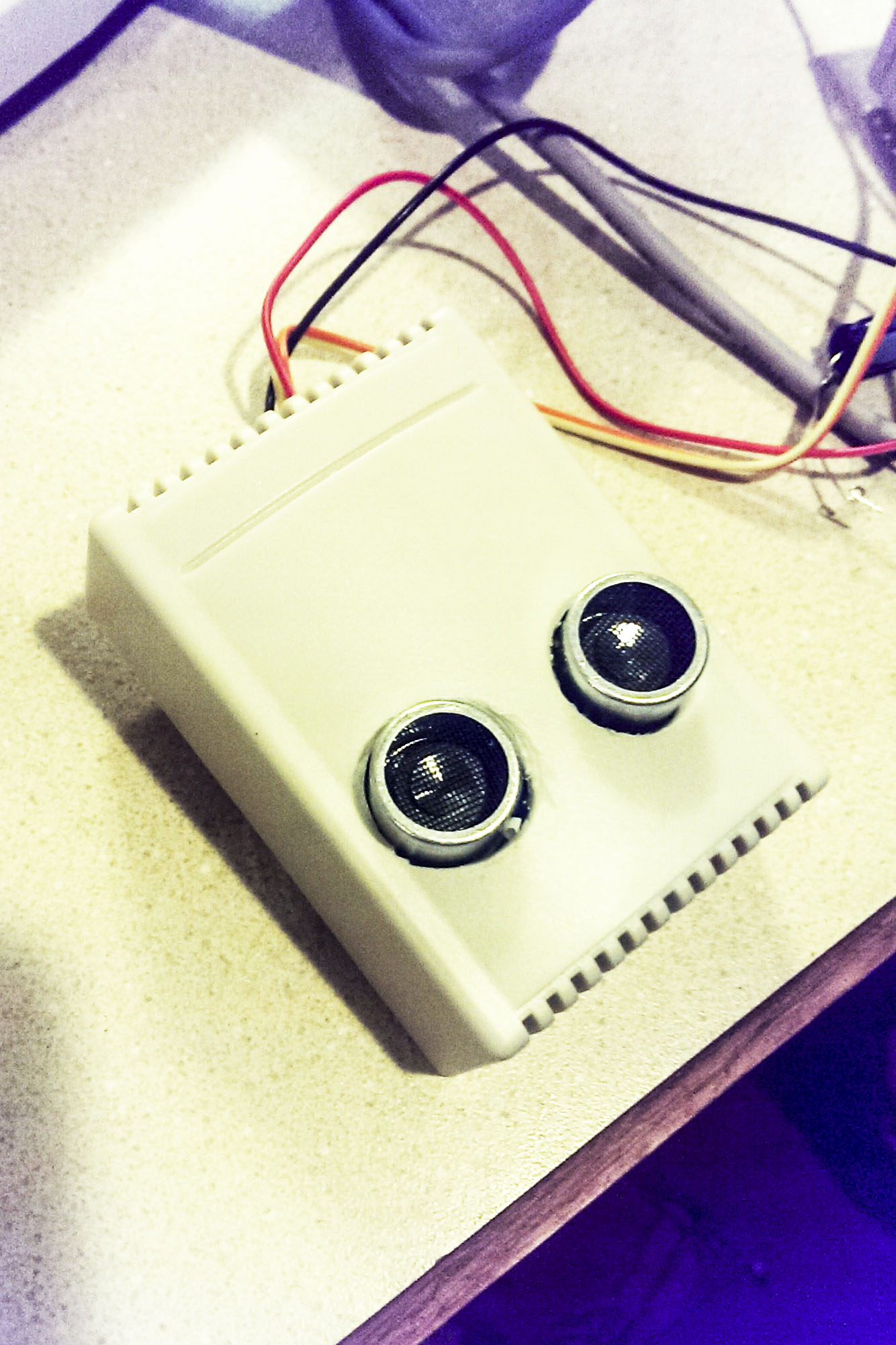
As far as wiring to the Arduino is concerned Hek spells all that out on the mysensor home page if you click on parking sensor. DI of the led ring goes to D4 on Arduino, Trig and echo of the distance sensor got to D6 and D5 of the Arduino respectively. Don't wire the led 5V to the Arduino. It should come directly from the power supply since when the leds are full on they can consume more power than the Arduino can supply. I plugged the Vcc and grnd connections from the distance sensor directly into the Ardouino's pins that were so marked. To be on the safe side I plan on using a 5V 2A DC power supply for this application. All grounds must be common.
-
@chilump I am moving from the prototype setup to the garage setup. The first picture shows the LED ring connections. I used solid copper wire because it facilitated what I wanted to do. I squeezed the ends of the wire to flatten them and bent them 90 degrees to make it a bit easier to solder to the solder pads on the led ring. The pads are marked D1,5V,GND and D0. D0 is not used in this application. These are the most difficult connections to make.
```
I mounted the ring on a square piece of 1/4 in particle board, drilling holes to feed the wires through. It only has a primer coat on it in the picture.
I will connect a 100uf between the 5v and ground connectors behind the board so it cannot be seen and then mount it on the garage wall.
Hek's 22uf recommendation is probably good enough, but in reading about led ring applications an the internet 100uf was recommended for Adafruit neopixel rings. How much you need is dependent on the led intensity and how rapidly the signal will be changing--for this case 22uf should be ok.I put the distance sensor in one of the standard cases.
As far as wiring to the Arduino is concerned Hek spells all that out on the mysensor home page if you click on parking sensor. DI of the led ring goes to D4 on Arduino, Trig and echo of the distance sensor got to D6 and D5 of the Arduino respectively. Don't wire the led 5V to the Arduino. It should come directly from the power supply since when the leds are full on they can consume more power than the Arduino can supply. I plugged the Vcc and grnd connections from the distance sensor directly into the Ardouino's pins that were so marked. To be on the safe side I plan on using a 5V 2A DC power supply for this application. All grounds must be common.
-
@Dan-S. Can a single 5v 2a adapter be used? In that case would everything be wired to the single power adapter?
-
@chilump I hope so since that's exactly how I intend to use it. I will wire the arduino and the led ring directly (and separately ) to the adaptor. I don't want to have to deal with 2 separate power supplies.
-
This is looking great!
But i'm not seeing any "sleeping" is there anyway to have this using the external interrupts on the arduino so it can be running on battery?
( sorry if i'm mistaken, i'm new to arduino :D ) -
@korttoma
Even if it's only active for about 3-4minutes per day?
The problem is i got no way of getting power to where i want to place it.
And also if i did it would have to be something like 230V to usb adapter.
And plugging one of those in outside seems like a fire hazzard (even indoors they are known to start fires).What if i hook it up to a small solar panel to charge the batteries?
Otherwise i guess i'll just have to stick with the old tennisball on a string method :D
-
@korttoma
Even if it's only active for about 3-4minutes per day?
The problem is i got no way of getting power to where i want to place it.
And also if i did it would have to be something like 230V to usb adapter.
And plugging one of those in outside seems like a fire hazzard (even indoors they are known to start fires).What if i hook it up to a small solar panel to charge the batteries?
Otherwise i guess i'll just have to stick with the old tennisball on a string method :D
@leothlon I'm not saying it can not be done but according to the datasheet the LED chip can consume up to 20mA ( http://www.adafruit.com/datasheets/WS2812.pdf ). So with 24 of them you will be looking at almost 500mA for just the LEDs.
http://ncalculators.com/electrical/battery-life-calculator.htm
btw, there is another thread about safe AC DC transformers here
- Tomas
-
@leothlon I'm not saying it can not be done but according to the datasheet the LED chip can consume up to 20mA ( http://www.adafruit.com/datasheets/WS2812.pdf ). So with 24 of them you will be looking at almost 500mA for just the LEDs.
http://ncalculators.com/electrical/battery-life-calculator.htm
btw, there is another thread about safe AC DC transformers here
@korttoma The online documentation I read said:
"The pin labeled PWR +5V is the power input pin, and should be connected to a suitable power supply. An input voltage of 5 V is used to power the ring, and each LED on the ring can draw up to 50 mA at 5 V when outputting white at full brightness. That means the ring could draw up to a maximum of around 1.2 A."
Although Hek's code does not operate all the pixels at full white brightness, I decided to play extra safe and use a 2A supply.
-
@korttoma The online documentation I read said:
"The pin labeled PWR +5V is the power input pin, and should be connected to a suitable power supply. An input voltage of 5 V is used to power the ring, and each LED on the ring can draw up to 50 mA at 5 V when outputting white at full brightness. That means the ring could draw up to a maximum of around 1.2 A."
Although Hek's code does not operate all the pixels at full white brightness, I decided to play extra safe and use a 2A supply.
@Dan-S. Yeah I'm sure thats true. Please post a link to the documentation if you can find it. Anyhow I guess we can agree that running this device on batteries would be difficult.
- Tomas
-
@Dan-S. Yeah I'm sure thats true. Please post a link to the documentation if you can find it. Anyhow I guess we can agree that running this device on batteries would be difficult.
-
@Dan-S. Yeah I'm sure thats true. Please post a link to the documentation if you can find it. Anyhow I guess we can agree that running this device on batteries would be difficult.
-
But isn't the distance sensor rather power hungry as well?
The dist-sensor but be awake all the time taking measurements (which needs to be interpreted by the MCU).. so sleep mode is not an option on this.
@hek said:
But isn't the distance sensor rather power hungry as well?
You could wake it with a reed switch attached to the garage door...
door open, sense and display until steady state and go to sleep on a timeout or door closed interrupt