How To - Doorbell Automation Hack
-
My wiring:
I discovered that they ran 4 conductor wire from the transformer in the basement to this location. So I plugged a phone charger in near the transformer, cut the end off a USB cable, and connected the 5V and gnd wires from that USB cable to the spare 2 wires in the cable. So then there's 6 wires coming into the doorbell as shown here: 2 for 16VAC from the transformer, 2 for 5VDC from the phone charger, and 2 from the doorbell button. I then connected the 5V pair to the top pair of screw terminals in the photo on the rboard. They're the blue and green wires. The white wire in the top terminal is one side of the button, connecting to ground there. The second side of the button is the red wire going into the grey wire nut. The brown wire coming out of the nut connects to the A0 pin on the board. Finally, the 2 16VAC wires are red and white. The red goes over to the right terminal on the plunger mechanism. The white goes to the common terminal on the rboard's relay connections. Finally, a black wire connects the NO from the relay to the other side of the plunger.
Hopefully that was all clear for anyone wanting to wire up their own!
-
Hello all,
I'm trying to hook this doorbell sensor up, what I've found is that when I connect it, I must connect it to NC. The downside is that when I reset the Arduino, the doorbell keeps ringing until pin4 is pulled up. How can I change that in the sketch?
Also I can ring it once, it rings and then it stops working. Connection to the gateway is lost and it won't ring either.
been trying to fix it for 3 days now, but I can't seem to figure out what I've done wrong.
Hooked up pin 4 to the input pin of the relay. The relay is directly powered by 5v coming from a usb hub with 2A.
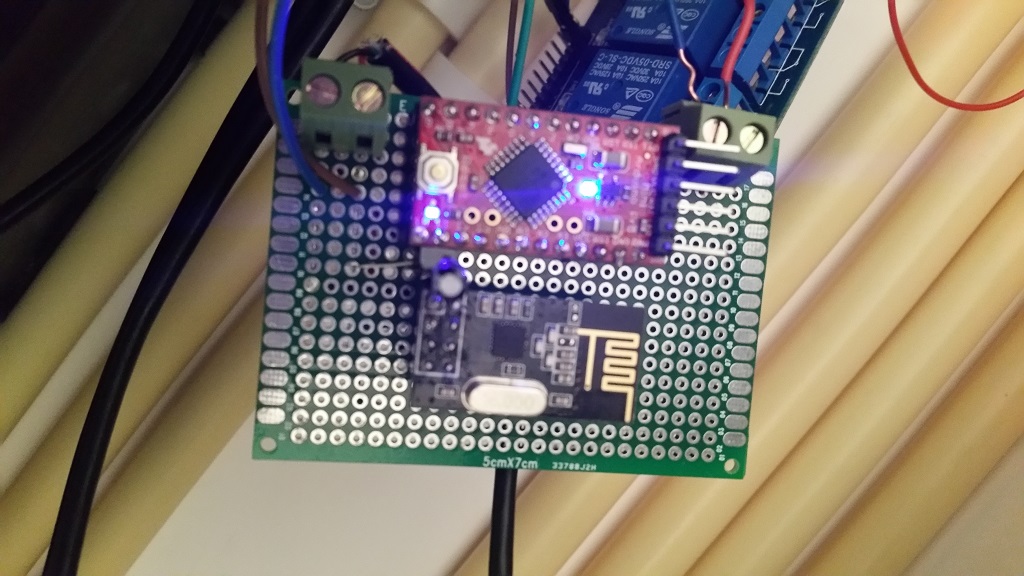
The Arduino is powered using the same 5V, with a regulator to the radio to give it 3.3V. Connected a 4.7uF cap directly on the radio.
When I reset the arduino this comes to the gateway:0;0;3;0;9;read: 16-16-0 s=255,c=0,t=17,pt=0,l=3,sg=0:1.5 0;0;3;0;9;read: 16-16-0 s=255,c=3,t=11,pt=0,l=16,sg=0:Doorbell Monito 0;0;3;0;9;read: 16-16-0 s=255,c=3,t=12,pt=0,l=3,sg=0:1.0 0;0;3;0;9;read: 16-16-0 s=1,c=0,t=3,pt=0,l=0,sg=0: 0;0;3;0;9;read: 16-16-0 s=0,c=0,t=1,pt=0,l=0,sg=0: 0;0;3;0;9;read: 16-16-255 s=255,c=3,t=7,pt=0,l=0,sg=0: 0;0;3;0;9;send: 0-0-16-16 s=255,c=3,t=8,pt=1,l=1,sg=0,st=fail:0I can connect perfectly to the gateway using MyMQTT on Android so I think it is failing on the side of the doorbell any help would be greatly appreciated!
-
Hello all,
I'm trying to hook this doorbell sensor up, what I've found is that when I connect it, I must connect it to NC. The downside is that when I reset the Arduino, the doorbell keeps ringing until pin4 is pulled up. How can I change that in the sketch?
Also I can ring it once, it rings and then it stops working. Connection to the gateway is lost and it won't ring either.
been trying to fix it for 3 days now, but I can't seem to figure out what I've done wrong.
Hooked up pin 4 to the input pin of the relay. The relay is directly powered by 5v coming from a usb hub with 2A.
The Arduino is powered using the same 5V, with a regulator to the radio to give it 3.3V. Connected a 4.7uF cap directly on the radio.
When I reset the arduino this comes to the gateway:0;0;3;0;9;read: 16-16-0 s=255,c=0,t=17,pt=0,l=3,sg=0:1.5 0;0;3;0;9;read: 16-16-0 s=255,c=3,t=11,pt=0,l=16,sg=0:Doorbell Monito 0;0;3;0;9;read: 16-16-0 s=255,c=3,t=12,pt=0,l=3,sg=0:1.0 0;0;3;0;9;read: 16-16-0 s=1,c=0,t=3,pt=0,l=0,sg=0: 0;0;3;0;9;read: 16-16-0 s=0,c=0,t=1,pt=0,l=0,sg=0: 0;0;3;0;9;read: 16-16-255 s=255,c=3,t=7,pt=0,l=0,sg=0: 0;0;3;0;9;send: 0-0-16-16 s=255,c=3,t=8,pt=1,l=1,sg=0,st=fail:0I can connect perfectly to the gateway using MyMQTT on Android so I think it is failing on the side of the doorbell any help would be greatly appreciated!
@arjen That's strange. You shouldn't need to connect it to NC. That means you are normally sending power to your doorbell unless it is rung. Are you sure you have the wires from your doorbell correct? You may want to double check them with a multimeter.
-
Just to make sure I've took some photo's.
When I take a multimeter and place it on the bottom two wires of the trafo I get zero rating.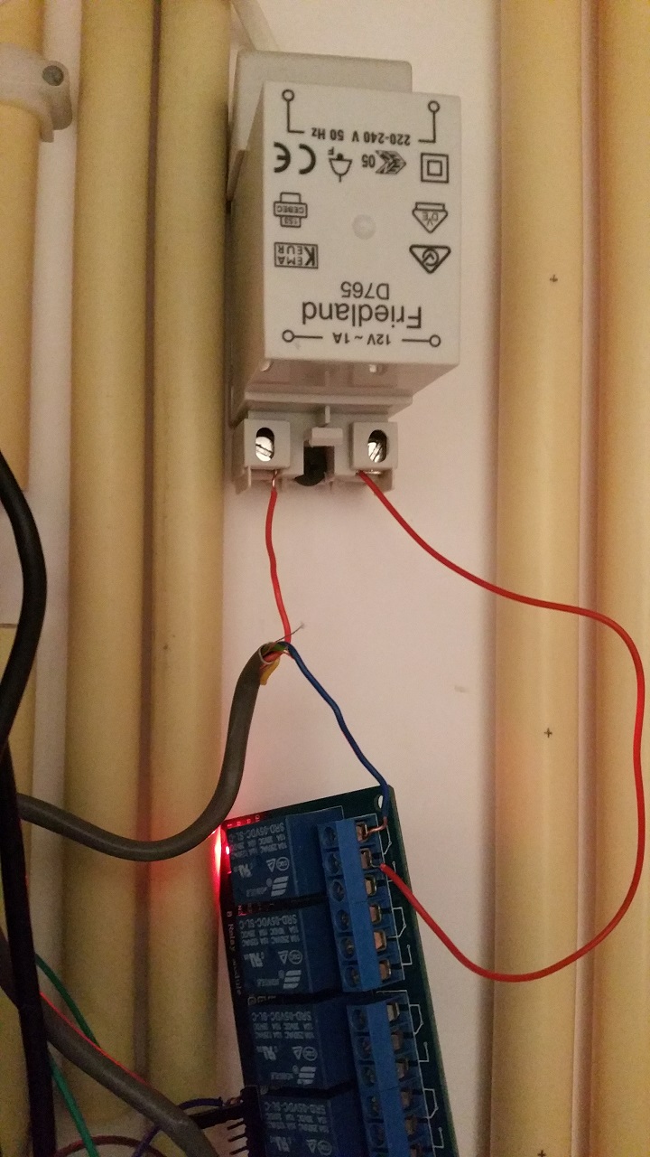
There is no difference between blue and red, neither does it make a difference if I change the wires in what ever way. Tried all possibilities I can think of. -
Yeah i know. Does it matter? It's seperated by the relay from the rest right?
Or am I saying something stupid here.... :confused: -
Sure, no prob.
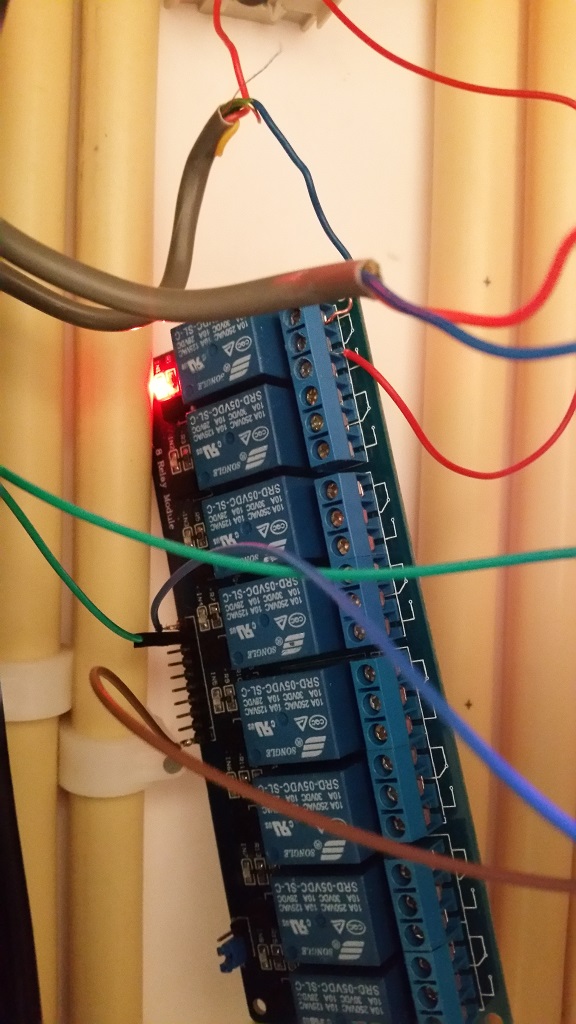
This is the relay, at the moment a 6 port, didn't had a one port available.
The green wire is connected to IN1 on the relay and pin4 on the arduino.
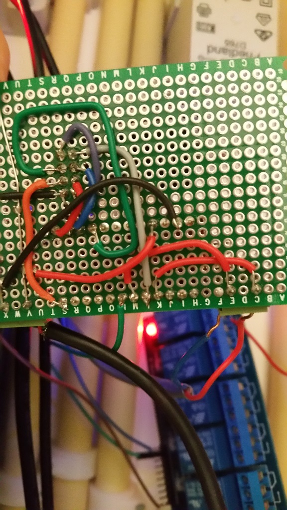
the backside of the print. The bottom row 'S' is pin 9 on the arduino, 'M' and 'K' is pin3 and Ground to doorbellbutton.
front side. The brown and blue on the left are 5V to the relay, on the right red and blue are input doorbellbutton. -
For the NC problem change:
#define RELAY_ON 1
#define RELAY_OFF 0
to:
#define RELAY_ON 0 #define RELAY_OFF 1 -
Huh, I have the same problem as @arjen is describing too, the only difference is i'm using a 2x raly vs. his 4. I don't have an issue with the relay being on, since my node is always powered on, the pull always goes high. Might just change it in the code/wiring though when I get the Arduino IDE working again.
Quick question: do you have the relay board powered by the Arduino, or another 5V source?
My Projects
2 Door Chime Sensor
Washing Machine Monitor -
Made the changes to the sketch as suggested, and now I can connect it to NO.
Just to make sure I didn't made a mistake while soldering, used a fresh nano and made all connections again. In the sketch the changes still need to be made, however as far as i could test this morning all is working fine now!
Thanks for all the tips!The relay is powered by the same powersource as the arduino (6 port powered usb hub 2A).
-
Huh, I have the same problem as @arjen is describing too, the only difference is i'm using a 2x raly vs. his 4. I don't have an issue with the relay being on, since my node is always powered on, the pull always goes high. Might just change it in the code/wiring though when I get the Arduino IDE working again.
Quick question: do you have the relay board powered by the Arduino, or another 5V source?
@drock1985 the relay should be powered by the same 5v power source as the Arduino but not from the arduino. It can draw too much power and cause issues when connected to the arduino.
@arjen Great! I just noticed the selection pin (can't think of the correct name right now) on your relay. I wonder if switching that would allow you to use the original code as well as the NO connections?
-
Excellent project, great work.. So I need to pick your mind.... I have a doorbell that can change music and volume. I hope to be able to fully control it by zwave using this app with Vera...Any ideas.....
-
Hello all - sorry I have been away for so long...
This bring back memories http://forum.mysensors.org/topic/1620/mysensored-doorbell
I wish I found a way of triggering the notification from the ring and not the other way around, as this way when something happen to your arduino the doorbell will not ring. Didn't happen yet - it works perfectly for 6 months but I would feel more relaxed if it was the other way around. Oh well... -
Hello all - sorry I have been away for so long...
This bring back memories http://forum.mysensors.org/topic/1620/mysensored-doorbell
I wish I found a way of triggering the notification from the ring and not the other way around, as this way when something happen to your arduino the doorbell will not ring. Didn't happen yet - it works perfectly for 6 months but I would feel more relaxed if it was the other way around. Oh well...@Moshe-Livne Cool! You can look at it the other way around on the Arduino processing the ring issue you raised. I now have the ability to turn off the ring if I want to. So I guess there is some give and take :)
My "How To" home automation video channel: https://www.youtube.com/channel/UCq_Evyh5PQALx4m4CQuxqkA
-
@Moshe-Livne Cool! You can look at it the other way around on the Arduino processing the ring issue you raised. I now have the ability to turn off the ring if I want to. So I guess there is some give and take :)
@petewill ummmm you could still cut the ring even if it was the other way around with a relay. Sorry to be a pain :-) can't fight my mold hehehe. generally I find the reliability of dorrbells (especially the old wired kind) to be excellent. mine has been working flawlessly for at least 35 years.
-
@petewill ummmm you could still cut the ring even if it was the other way around with a relay. Sorry to be a pain :-) can't fight my mold hehehe. generally I find the reliability of dorrbells (especially the old wired kind) to be excellent. mine has been working flawlessly for at least 35 years.
@Moshe-Livne Ok, I must have misunderstood. I thought you wanted the bell to ring no matter what then just detect the signal so you could send it to your gateway. Either way, that's why MySensors is so great, you can do pretty much what ever YOU want, not what someone else wants :)
My "How To" home automation video channel: https://www.youtube.com/channel/UCq_Evyh5PQALx4m4CQuxqkA