Skip to content
  • MySensors
  • OpenHardware.io
  • Categories
  • Recent
  • Tags
  • Popular
Skins
  • Light
  • Brite
  • Cerulean
  • Cosmo
  • Flatly
  • Journal
  • Litera
  • Lumen
  • Lux
  • Materia
  • Minty
  • Morph
  • Pulse
  • Sandstone
  • Simplex
  • Sketchy
  • Spacelab
  • United
  • Yeti
  • Zephyr
  • Dark
  • Cyborg
  • Darkly
  • Quartz
  • Slate
  • Solar
  • Superhero
  • Vapor

  • Default (No Skin)
  • No Skin
Collapse
Brand Logo
  1. Home
  2. My Project
  3. My Slim 2AA Battery Node

My Slim 2AA Battery Node

Scheduled Pinned Locked Moved My Project
498 Posts 71 Posters 342.6k Views 69 Watching
  • Oldest to Newest
  • Newest to Oldest
  • Most Votes
Reply
  • Reply as topic
Log in to reply
This topic has been deleted. Only users with topic management privileges can see it.
  • Cliff KarlssonC Offline
    Cliff KarlssonC Offline
    Cliff Karlsson
    wrote on last edited by
    #214

    Ok, finaly succeded in burning the bootloader. Now comes next part. Fuses and lockbits, I have no idea what this means but is this what I need to do?

    avrdude -C ../etc/avrdude.conf -c usbasp -B5 -p ATmega328P -U lfuse:w:0x62:m -U hfuse:w:0xDE:m -U efuse:w:0x07:m -U lock:w:0x2F:m
    
    m26872M 1 Reply Last reply
    1
    • M Offline
      M Offline
      meddie
      wrote on last edited by
      #215

      oh, yes! And you have to be carefully with them, because to set the fuses wrong, can destroy your µcontroller

      1 Reply Last reply
      0
      • M Offline
        M Offline
        meddie
        wrote on last edited by
        #216

        if you look to message Nr 179 you will find my bootloader and the correct fuses for this. But its a 1MHz Bootloader and the fuses too.
        Dont use it if you want to run it at 8 MHz.

        1 Reply Last reply
        0
        • bjacobseB Offline
          bjacobseB Offline
          bjacobse
          wrote on last edited by
          #217

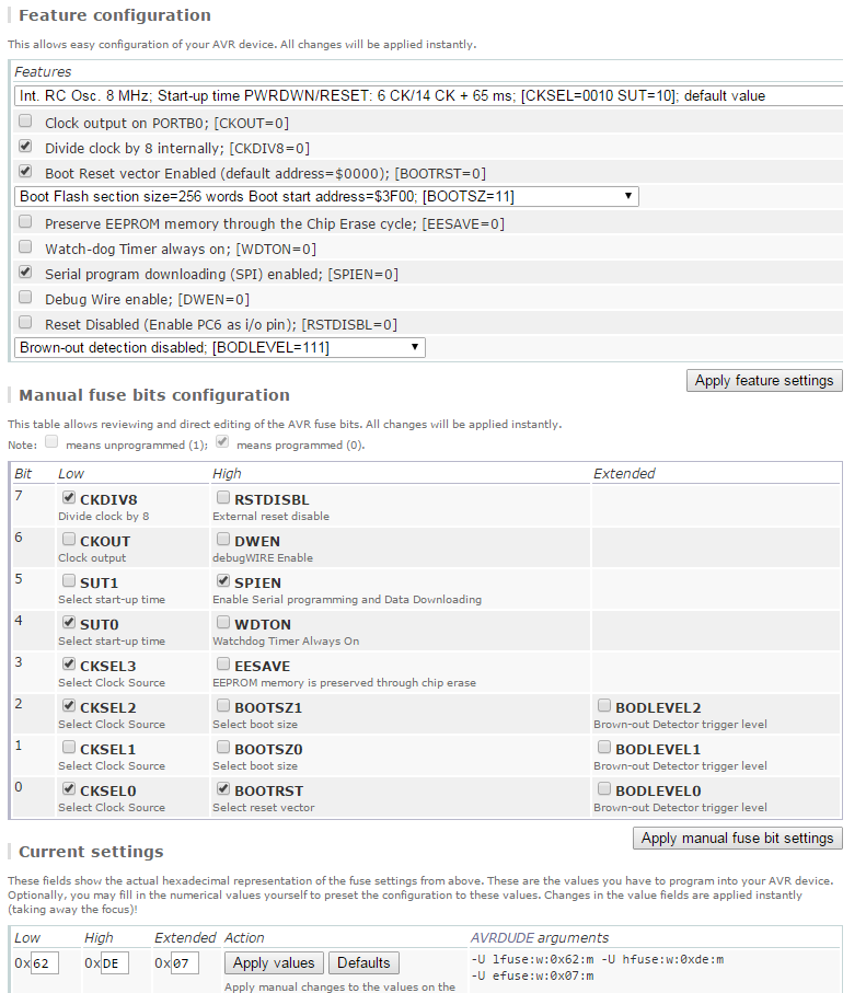
          Web-based fuse calculator
          A different way of evaluating fuses is presented at this web page:
          http://www.engbedded.com/fusecalc

          At the bottom I inserted your fuses.
          Translation:
          Divide by8-> if your mcy board uses 8Mhz, then you now use 1Mhz Clock (Good this enables that you now can use a lower voltage down to 1,9V)
          SPI is enabled, then you can program your mcu with FTDI cable
          BOD mcu will not power down mcu when you have a low voltage (So you can use down to 1,9V)
          I write 1,9Volt since this is the lowest voltage your NRF24L01+ can use for operation

          0_1454685582246_upload-5f146d65-d819-455d-8d3c-ed029eb79abb

          1 Reply Last reply
          0
          • Cliff KarlssonC Offline
            Cliff KarlssonC Offline
            Cliff Karlsson
            wrote on last edited by
            #218

            Sorry for asking the same questions over and over but I have just used the files linked at the top of this thread.

            This is the bootloader that I used:

            atmega328_1a.hex (Optiboot for 9600baud at 1MHz)
            
            
            ##############################################################
            # Add the new board to boards.txt (normally located at "C:\Program Files\Arduino\hardware\arduino\avr"
            # The *.bootloader.* etries only matters if you want to program bootloader (and fuses) from Arduino IDE. 
            # See http://www.engbedded.com/fusecalc (select Atmega328p) for interpretation of fuse values and how 
            # extended fuses are written in different applications (07h in Arduino IDE = FFh in Atmel studio).
            ##############################################################
            
            apm96.name=APM Optiboot internal 1MHz noBOD 9600baud
            
            apm96.upload.tool=avrdude
            apm96.upload.protocol=arduino
            apm96.upload.maximum_size=32256
            apm96.upload.speed=9600
            apm96.bootloader.tool=avrdude
            apm96.bootloader.low_fuses=0x62
            apm96.bootloader.high_fuses=0xde
            apm96.bootloader.extended_fuses=0x07
            apm96.bootloader.path=optiboot_v50
            apm96.bootloader.file=atmega328_1a.hex
            apm96.bootloader.unlock_bits=0x3F
            apm96.bootloader.lock_bits=0x2F
            apm96.build.mcu=atmega328p
            apm96.build.f_cpu=1000000L
            apm96.build.core=arduino
            apm96.build.variant=standard


            Do I still need to add fuses or is that done when the bootloader is burned?

            ahmedadelhosniA 1 Reply Last reply
            0
            • Cliff KarlssonC Cliff Karlsson

              Sorry for asking the same questions over and over but I have just used the files linked at the top of this thread.

              This is the bootloader that I used:

              atmega328_1a.hex (Optiboot for 9600baud at 1MHz)
              
              
              ##############################################################
              # Add the new board to boards.txt (normally located at "C:\Program Files\Arduino\hardware\arduino\avr"
              # The *.bootloader.* etries only matters if you want to program bootloader (and fuses) from Arduino IDE. 
              # See http://www.engbedded.com/fusecalc (select Atmega328p) for interpretation of fuse values and how 
              # extended fuses are written in different applications (07h in Arduino IDE = FFh in Atmel studio).
              ##############################################################
              
              apm96.name=APM Optiboot internal 1MHz noBOD 9600baud
              
              apm96.upload.tool=avrdude
              apm96.upload.protocol=arduino
              apm96.upload.maximum_size=32256
              apm96.upload.speed=9600
              apm96.bootloader.tool=avrdude
              apm96.bootloader.low_fuses=0x62
              apm96.bootloader.high_fuses=0xde
              apm96.bootloader.extended_fuses=0x07
              apm96.bootloader.path=optiboot_v50
              apm96.bootloader.file=atmega328_1a.hex
              apm96.bootloader.unlock_bits=0x3F
              apm96.bootloader.lock_bits=0x2F
              apm96.build.mcu=atmega328p
              apm96.build.f_cpu=1000000L
              apm96.build.core=arduino
              apm96.build.variant=standard


              Do I still need to add fuses or is that done when the bootloader is burned?

              ahmedadelhosniA Offline
              ahmedadelhosniA Offline
              ahmedadelhosni
              wrote on last edited by
              #219

              @Cliff-Karlsson

              It is already done when you burn the bootloader.

              apm96.bootloader.low_fuses=0x62
              apm96.bootloader.high_fuses=0xde

              1 Reply Last reply
              0
              • Cliff KarlssonC Cliff Karlsson

                Ok, finaly succeded in burning the bootloader. Now comes next part. Fuses and lockbits, I have no idea what this means but is this what I need to do?

                avrdude -C ../etc/avrdude.conf -c usbasp -B5 -p ATmega328P -U lfuse:w:0x62:m -U hfuse:w:0xDE:m -U efuse:w:0x07:m -U lock:w:0x2F:m
                
                m26872M Offline
                m26872M Offline
                m26872
                Hardware Contributor
                wrote on last edited by
                #220

                @Cliff-Karlsson said:

                Ok, finaly succeded in burning the bootloader.

                Great news!! With Arduino as ISP? Any particular tips to share?

                1 Reply Last reply
                0
                • Cliff KarlssonC Offline
                  Cliff KarlssonC Offline
                  Cliff Karlsson
                  wrote on last edited by
                  #221

                  @m26872 I am fairly sure that all methods work in normal cases but nothing worked for me fore some reason :) .

                  The only way I could get it to work was when I finaly put the chip in an Arduino Uno clone with 328p Dip(?) socket and connected an USBtiny ISP to the ISCP of that Uno. It took just a couple of seconds and then it was done :).

                  I flashed like 6-7 ships right away with bootloader and blink-sketch just for fun. Biggest problem now is to get the damn chip in/out of the sockets without bending any legs. But I ordered a chip extractor to remedy that problem (in 4-6 weeks :()

                  m26872M bjacobseB 2 Replies Last reply
                  2
                  • Cliff KarlssonC Cliff Karlsson

                    @m26872 I am fairly sure that all methods work in normal cases but nothing worked for me fore some reason :) .

                    The only way I could get it to work was when I finaly put the chip in an Arduino Uno clone with 328p Dip(?) socket and connected an USBtiny ISP to the ISCP of that Uno. It took just a couple of seconds and then it was done :).

                    I flashed like 6-7 ships right away with bootloader and blink-sketch just for fun. Biggest problem now is to get the damn chip in/out of the sockets without bending any legs. But I ordered a chip extractor to remedy that problem (in 4-6 weeks :()

                    m26872M Offline
                    m26872M Offline
                    m26872
                    Hardware Contributor
                    wrote on last edited by
                    #222

                    @Cliff-Karlsson
                    :thumbsup:

                    To get the ICs out from the DIP socket, I just use a small screw driver (2-3mm) and gently push it all the way under from one side only. And of course, don't push in the IC to hard to begin with.

                    1 Reply Last reply
                    0
                    • Cliff KarlssonC Cliff Karlsson

                      @m26872 I am fairly sure that all methods work in normal cases but nothing worked for me fore some reason :) .

                      The only way I could get it to work was when I finaly put the chip in an Arduino Uno clone with 328p Dip(?) socket and connected an USBtiny ISP to the ISCP of that Uno. It took just a couple of seconds and then it was done :).

                      I flashed like 6-7 ships right away with bootloader and blink-sketch just for fun. Biggest problem now is to get the damn chip in/out of the sockets without bending any legs. But I ordered a chip extractor to remedy that problem (in 4-6 weeks :()

                      bjacobseB Offline
                      bjacobseB Offline
                      bjacobse
                      wrote on last edited by
                      #223

                      @Cliff-Karlsson
                      You shall buy Textool ZIF socket. not sure which fits your Arduino, If you at some point get's lazy (Solder less, and accept to use a little more space) and use Arduino Pro Mini then textool 224-3344 ZIF will be your friend

                      1 Reply Last reply
                      0
                      • rsachocR Offline
                        rsachocR Offline
                        rsachoc
                        wrote on last edited by
                        #224

                        Hi all, I'm seeing replies, but I'm not sure if any are aimed at my question? I think not?

                        m26872M 1 Reply Last reply
                        0
                        • rsachocR rsachoc

                          Hi all, I'm seeing replies, but I'm not sure if any are aimed at my question? I think not?

                          m26872M Offline
                          m26872M Offline
                          m26872
                          Hardware Contributor
                          wrote on last edited by
                          #225

                          @rsachoc
                          I've started a new thread aimed at your question. I'll soon delete much of the content in the post you based your question on and refer to the new thread instead.

                          1 Reply Last reply
                          1
                          • M Offline
                            M Offline
                            meddie
                            wrote on last edited by
                            #226

                            it would be nice when a atsha204 a an a flash rom where placed to pcb for signing and ota

                            m26872M 1 Reply Last reply
                            1
                            • M meddie

                              it would be nice when a atsha204 a an a flash rom where placed to pcb for signing and ota

                              m26872M Offline
                              m26872M Offline
                              m26872
                              Hardware Contributor
                              wrote on last edited by m26872
                              #227

                              @meddie I don't use any of it myself yet, but I know it's only a matter of time until they'll be needed. I think a add-on board to all already existing nodes would be my personal priority then, but new users would prefer it on-board of course and only populate if needed. I'll put on my not yet posted future requests list. (I remember top-side labels are also wanted.) A thing to remember though, is that my Slim Node design is a concept was a lean and simplicity concept, without preparations for maximum flexibility etc.

                              As I've said earlier - if anyone like to do their own Slim Node design, you're very welcome. And if you share it, it's even better.

                              1 Reply Last reply
                              2
                              • GertSandersG Offline
                                GertSandersG Offline
                                GertSanders
                                Hardware Contributor
                                wrote on last edited by
                                #228

                                @m26872: slowly getting there: http://forum.mysensors.org/topic/3043/new-nrf24l01-smd/14

                                m26872M 1 Reply Last reply
                                0
                                • M Offline
                                  M Offline
                                  meddie
                                  wrote on last edited by
                                  #229

                                  What i like on this node is the great idea with the casing. To use a cable duct is a great idea. We have wooden windows and i found in a diy market cable ducts in wooden look
                                  like this:
                                  wooden look cable duct

                                  The Problem is that the size is 15x15 mm outside. inside the pcb can be max. 13 mm.

                                  m26872M 1 Reply Last reply
                                  0
                                  • M meddie

                                    What i like on this node is the great idea with the casing. To use a cable duct is a great idea. We have wooden windows and i found in a diy market cable ducts in wooden look
                                    like this:
                                    wooden look cable duct

                                    The Problem is that the size is 15x15 mm outside. inside the pcb can be max. 13 mm.

                                    m26872M Offline
                                    m26872M Offline
                                    m26872
                                    Hardware Contributor
                                    wrote on last edited by
                                    #230

                                    @meddie I think 15x15 is very common and should be to prefer, but if I remember correct there's not enough space for AA batteries, or is there?

                                    1 Reply Last reply
                                    1
                                    • GertSandersG GertSanders

                                      @m26872: slowly getting there: http://forum.mysensors.org/topic/3043/new-nrf24l01-smd/14

                                      m26872M Offline
                                      m26872M Offline
                                      m26872
                                      Hardware Contributor
                                      wrote on last edited by
                                      #231

                                      @GertSanders Good job! If you go the SMD way I think a lot could be done. Perhaps matching AAA width? Leave some (only few) SMD pads open for sensor connection, no proto area, etc.

                                      GertSandersG 1 Reply Last reply
                                      0
                                      • M Offline
                                        M Offline
                                        meddie
                                        wrote on last edited by
                                        #232

                                        oh, yes. You have right, the battery fits in it, but its a little bit too big so i cant close the cover. Damn i didnt try it before.
                                        ok the i have to look for a graeter duct.

                                        1 Reply Last reply
                                        0
                                        • AWIA Offline
                                          AWIA Offline
                                          AWI
                                          Hero Member
                                          wrote on last edited by
                                          #233

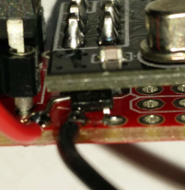
                                          Currently this is my favorite board. Minimal size, traditional components and just enough breadboard space. A few variations:
                                          0_1454859878498_upload-23af4fbe-6938-4079-9fc4-d149c8950370 Soldered an 8 mHz resonator (a 'crystal' which does not need the capacitors) for a more stable clock.

                                          0_1454860192227_upload-c6f3a164-b5cb-43f5-af82-c556674568f4 0_1454860883223_upload-351808cf-868d-4076-80ce-2e4b05ec4898 Soldered a 3.3v LDO (662k) under the radio to have it powered with a rechargeable Lipo (4.1V max) battery. And added a voltage divider to measure the actual battery voltage.

                                          0_1454860058592_upload-a677913a-22a8-466d-920d-ae620591088b 0_1454860344864_upload-77335242-a0b4-4371-85f5-4d11731c0868
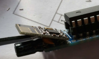
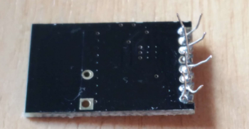
                                          With a SMD version of the radio. Needs some creative soldering...

                                          0_1454860702395_upload-e1af1f72-11c5-409d-9eca-762e3c657183 Compared to an other favourite ( @GertSanders )

                                          It would even be better if the smd radio could be soldered on the board. Kicad is giving me a headache so if anybody wants to volunteer with a panelized design.... (I will reward you with a free batch of 'dirty' boards, just drop me a pm)

                                          YveauxY 1 Reply Last reply
                                          1
                                          Reply
                                          • Reply as topic
                                          Log in to reply
                                          • Oldest to Newest
                                          • Newest to Oldest
                                          • Most Votes


                                          10

                                          Online

                                          11.7k

                                          Users

                                          11.2k

                                          Topics

                                          113.0k

                                          Posts


                                          Copyright 2019 TBD   |   Forum Guidelines   |   Privacy Policy   |   Terms of Service
                                          • Login

                                          • Don't have an account? Register

                                          • Login or register to search.
                                          • First post
                                            Last post
                                          0
                                          • MySensors
                                          • OpenHardware.io
                                          • Categories
                                          • Recent
                                          • Tags
                                          • Popular