My Slim 2AA Battery Node
-
What were the winning fuse settings that you finally settled on using? Trust me, a year from now you won't remember, and you'll be glad you posted it.
-
OK MY solution was actually the fuses that I said earlier . but confused myself by changing them back and forth a couple of times and downgraded Arduino to the previous version etc.
So the fuses for my barebone 328P are:
proMYSBL8.bootloader.low_fuses=0xE2
proMYSBL8.bootloader.high_fuses=0xDA
proMYSBL8.bootloader.extended_fuses=0xFEthe biggest issue I had was probably with ARduino IDE .. that one I enver manged to set the fuses ( I read somewhere it should.. but maybe I´m wrong) . Anyway it works when I set the fuses and upload it with AVRDUDESS.
(note: hello me 1 year into the future, just do what I say ! )
=) -
I just add another note to myself ( And anyone else that lost their hair wondering why the bootloader was lost....)
DO NOT UPLOAD SKETCH ONLY WITH USBASP ... it deletes the bootloader .
yes I know it is mentioned on the foru m.. just found it .. but I mention it again... -
I just add another note to myself ( And anyone else that lost their hair wondering why the bootloader was lost....)
DO NOT UPLOAD SKETCH ONLY WITH USBASP ... it deletes the bootloader .
yes I know it is mentioned on the foru m.. just found it .. but I mention it again...and here is a good simple explanation of the fuses
http://www.martyncurrey.com/category/atmega/ -
FYI: If you run the ceramic resonator at 8mhz, with the zero wake up fuse setting, you can wake the atmega328p up in less than 4usec. This is a huge power savings compared to all other options.
-
FYI: If you run the ceramic resonator at 8mhz, with the zero wake up fuse setting, you can wake the atmega328p up in less than 4usec. This is a huge power savings compared to all other options.
-
@badmannen You're welcome. I even measured it on an oscope just to be sure, so I'm certain it is true.
-
This style?
€ 1,09 8%OFF | 20pcs Ceramic Resonators ZTT 4M 6M 8M 10M 12M 16M 4/6/8/10/12/16MHZ DIP-3 Crystal Frequency Element
https://s.click.aliexpress.com/e/mRfXWk8Nd -
This style?
€ 1,09 8%OFF | 20pcs Ceramic Resonators ZTT 4M 6M 8M 10M 12M 16M 4/6/8/10/12/16MHZ DIP-3 Crystal Frequency Element
https://s.click.aliexpress.com/e/mRfXWk8Nd@badmannen no. It's built in. You already have it.
-
@badmannen no. It's built in. You already have it.
-
@neverdie aa ok sorry got confused there for a second. I'm running the internal, so I guess I will pop them off again now then and burn that fuse for a quicker startup 👍🏻
@badmannen yes, it must be the internal resonator.
-
Hello, will there be a good soul that will help improve the program? I know what the error is but I have no idea how to correct it.
interruptReturn = sleep(PRIMARY_BUTTON_PIN-2, CHANGE, SECONDARY_BUTTON_PIN-2, CHANGE, ONE_DAY_SLEEP_TIME);when i change
PRIMARY_BUTTON_PINthe interruptReturn = 1, but when i change
SECONDARY_BUTTON_PINthe interruptReturn = 0.
My question is how can i chane it to send 1 and 1 by both contactrons.Full code:
//#define MY_DEBUG #define MY_RADIO_NRF24 #define MY_NODE_ID 100 #define MY_PARENT_NODE_ID 0 #define MY_PARENT_NODE_IS_STATIC #include <MySensors.h> #include "Vcc.h" #define SKETCH_NAME "WindowSlimSensor2pcs_smallR" #define PRIMARY_CHILD_ID 1 #define PRIMARY_BUTTON_PIN 2 #define SECONDARY_CHILD_ID 2 #define SECONDARY_BUTTON_PIN 3 #define BATTERY_REPORT_DAY 2 // Desired heartbeat interval when inactive. Maximum heartbeat/report interval is equal to this due to the dayCounter. #define BATTERY_REPORT_BY_IRT_CYCLE 10 // Adjust this according to usage frequency. #define ONE_DAY_SLEEP_TIME 86400000 //#define BATTERY 3 MyMessage msg(PRIMARY_CHILD_ID, V_TRIPPED); MyMessage msg2(SECONDARY_CHILD_ID, V_TRIPPED); //MyMessage msg3(BATTERY, V_CUSTOM); int dayCounter = 0; int irtCounter = 0; bool interruptReturn=false; const float VccMin = 1.7; // Minimum expected Vcc level, in Volts. const float VccMax = 3.3; // Maximum expected Vcc level, in Volts. const float VccCorrection = 3.43 / 3.455; // Measured Vcc by multimeter divided by reported Vcc const int32_t report_interval = 8640000; // 1day -> h * m * s * ms NOTICE: milliseconds, not microseconds! Vcc vcc(VccCorrection); //Vcc vcc; #ifdef MY_DEBUG void before(){ Serial.begin(9600); } #endif void setup() { pinMode(PRIMARY_BUTTON_PIN, INPUT); pinMode(SECONDARY_BUTTON_PIN, INPUT); //EXTERNAL pull-ups digitalWrite(PRIMARY_BUTTON_PIN, LOW); digitalWrite(SECONDARY_BUTTON_PIN, LOW); } void presentation() { sendSketchInfo(SKETCH_NAME, __DATE__); present(PRIMARY_CHILD_ID, S_DOOR, "Lewe Okno"); present(SECONDARY_CHILD_ID, S_DOOR, "Prawe Okno"); // present(BATTERY, S_CUSTOM); } void loop() { uint8_t reedState; uint8_t reedState2; static uint8_t lastReedState = 2; static uint8_t lastReedState2 = 2; sleep(5); // Short delay to allow buttons to properly settle reedState = digitalRead(PRIMARY_BUTTON_PIN); sleep(5); // Short delay to allow buttons to properly settle reedState2 = digitalRead(SECONDARY_BUTTON_PIN); if (!interruptReturn) { // Woke up by timer (or first run) dayCounter++; if (dayCounter >= BATTERY_REPORT_DAY) { dayCounter = 0; sendBatteryReport(); } } else { // Woke up by pin change irtCounter++; sleep(5); // Woke up by pin change if (reedState != lastReedState) { send(msg.set(reedState==HIGH ? 1 : 0)); lastReedState = reedState; } if (reedState2 != lastReedState2) { send(msg2.set(reedState2==HIGH ? 1 : 0)); lastReedState2 = reedState2; } if (irtCounter>=BATTERY_REPORT_BY_IRT_CYCLE) { irtCounter=0; sendBatteryReport(); } } // Sleep until something happens with the sensor, or one sleep_time has passed since last awake. interruptReturn = sleep(PRIMARY_BUTTON_PIN-2, CHANGE, SECONDARY_BUTTON_PIN-2, CHANGE, ONE_DAY_SLEEP_TIME); } void sendBatteryReport() { uint8_t batteryPercent = (uint8_t)vcc.Read_Perc(VccMin, VccMax); sendBatteryLevel(batteryPercent); } -
Hello, will there be a good soul that will help improve the program? I know what the error is but I have no idea how to correct it.
interruptReturn = sleep(PRIMARY_BUTTON_PIN-2, CHANGE, SECONDARY_BUTTON_PIN-2, CHANGE, ONE_DAY_SLEEP_TIME);when i change
PRIMARY_BUTTON_PINthe interruptReturn = 1, but when i change
SECONDARY_BUTTON_PINthe interruptReturn = 0.
My question is how can i chane it to send 1 and 1 by both contactrons.Full code:
//#define MY_DEBUG #define MY_RADIO_NRF24 #define MY_NODE_ID 100 #define MY_PARENT_NODE_ID 0 #define MY_PARENT_NODE_IS_STATIC #include <MySensors.h> #include "Vcc.h" #define SKETCH_NAME "WindowSlimSensor2pcs_smallR" #define PRIMARY_CHILD_ID 1 #define PRIMARY_BUTTON_PIN 2 #define SECONDARY_CHILD_ID 2 #define SECONDARY_BUTTON_PIN 3 #define BATTERY_REPORT_DAY 2 // Desired heartbeat interval when inactive. Maximum heartbeat/report interval is equal to this due to the dayCounter. #define BATTERY_REPORT_BY_IRT_CYCLE 10 // Adjust this according to usage frequency. #define ONE_DAY_SLEEP_TIME 86400000 //#define BATTERY 3 MyMessage msg(PRIMARY_CHILD_ID, V_TRIPPED); MyMessage msg2(SECONDARY_CHILD_ID, V_TRIPPED); //MyMessage msg3(BATTERY, V_CUSTOM); int dayCounter = 0; int irtCounter = 0; bool interruptReturn=false; const float VccMin = 1.7; // Minimum expected Vcc level, in Volts. const float VccMax = 3.3; // Maximum expected Vcc level, in Volts. const float VccCorrection = 3.43 / 3.455; // Measured Vcc by multimeter divided by reported Vcc const int32_t report_interval = 8640000; // 1day -> h * m * s * ms NOTICE: milliseconds, not microseconds! Vcc vcc(VccCorrection); //Vcc vcc; #ifdef MY_DEBUG void before(){ Serial.begin(9600); } #endif void setup() { pinMode(PRIMARY_BUTTON_PIN, INPUT); pinMode(SECONDARY_BUTTON_PIN, INPUT); //EXTERNAL pull-ups digitalWrite(PRIMARY_BUTTON_PIN, LOW); digitalWrite(SECONDARY_BUTTON_PIN, LOW); } void presentation() { sendSketchInfo(SKETCH_NAME, __DATE__); present(PRIMARY_CHILD_ID, S_DOOR, "Lewe Okno"); present(SECONDARY_CHILD_ID, S_DOOR, "Prawe Okno"); // present(BATTERY, S_CUSTOM); } void loop() { uint8_t reedState; uint8_t reedState2; static uint8_t lastReedState = 2; static uint8_t lastReedState2 = 2; sleep(5); // Short delay to allow buttons to properly settle reedState = digitalRead(PRIMARY_BUTTON_PIN); sleep(5); // Short delay to allow buttons to properly settle reedState2 = digitalRead(SECONDARY_BUTTON_PIN); if (!interruptReturn) { // Woke up by timer (or first run) dayCounter++; if (dayCounter >= BATTERY_REPORT_DAY) { dayCounter = 0; sendBatteryReport(); } } else { // Woke up by pin change irtCounter++; sleep(5); // Woke up by pin change if (reedState != lastReedState) { send(msg.set(reedState==HIGH ? 1 : 0)); lastReedState = reedState; } if (reedState2 != lastReedState2) { send(msg2.set(reedState2==HIGH ? 1 : 0)); lastReedState2 = reedState2; } if (irtCounter>=BATTERY_REPORT_BY_IRT_CYCLE) { irtCounter=0; sendBatteryReport(); } } // Sleep until something happens with the sensor, or one sleep_time has passed since last awake. interruptReturn = sleep(PRIMARY_BUTTON_PIN-2, CHANGE, SECONDARY_BUTTON_PIN-2, CHANGE, ONE_DAY_SLEEP_TIME); } void sendBatteryReport() { uint8_t batteryPercent = (uint8_t)vcc.Read_Perc(VccMin, VccMax); sendBatteryLevel(batteryPercent); }Welcome to the forum @Grzegorz-B
Change
bool interruptReturn=false;to
uint8_t interruptReturn= INTERRUPT_NOT_DEFINED;and
if (!interruptReturn) { // Woke up by timer (or first run)to
if (interruptReturn== MY_WAKE_UP_BY_TIMER) { // Woke up by timer (or first run)Documentation for the sleep function is available at https://www.mysensors.org/download/sensor_api_20#sleeping
-
Welcome to the forum @Grzegorz-B
Change
bool interruptReturn=false;to
uint8_t interruptReturn= INTERRUPT_NOT_DEFINED;and
if (!interruptReturn) { // Woke up by timer (or first run)to
if (interruptReturn== MY_WAKE_UP_BY_TIMER) { // Woke up by timer (or first run)Documentation for the sleep function is available at https://www.mysensors.org/download/sensor_api_20#sleeping
@mfalkvidd Thanks! now its works like a charm :D
-
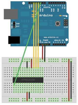
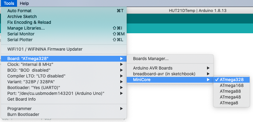
I built a Temp/Hum sensor using Slim Node few years back on Mys 1.5x and it was working for so long without any issues. Now I am trying to upgrade it to Mys 2.2x. I successfully loaded the bootloader on a new ATMEGA 328P-PU. Bootloader I used is minicore as recommended by @m26872 in his original post. I used the "Arduino as ISP" method to load the bootloader as explained in this tutorial How to burn 1Mhz & 8Mhz bootloader using Arduino IDE 1.6.5-r5.
Here are the settings I used in my Arduino IDE when loading the bootloader,
- internal clock 8 Mhz ( again based on the recommendation from the original post)
- BOD disabled
- Compiler LTO disabled
- Variant "328P/328PA"
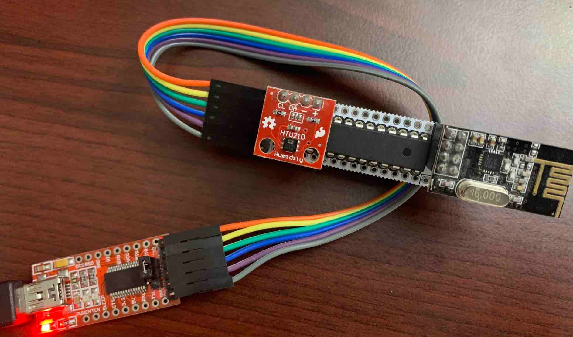
Now I am trying to upload the temperature/Hum Sketch using FTDI cable with the jumper set at 3.3v, I am getting the "stk500_recv(): programmer is not responding" error. Here is how I am connecting from FTDI to Slimnode and the same configuration has worked originally when I built the node but now it is failing.
Could some experts in this forum please help me to bring my node back to work?
Sorry about the long post. Appreciate your help.
-
Hi,
this is an awesome project and after waiting for weeks to get all parts, I finally started building.
The problem I am facing is that it seems that I cannot get the board working if I use such a 8-pin connector socket. I am generally OK with NOT using such a socket for sensors that "go into production" but for some sensors where space is not an issue or for boards which I want to use for testing different NRF24s etc, I would like to make the socket work.
Does anybody have any tipps on how to make the radio reliably work with a socket? That would be awesome!
Hello! It looks like you're interested in this conversation, but you don't have an account yet.
Getting fed up of having to scroll through the same posts each visit? When you register for an account, you'll always come back to exactly where you were before, and choose to be notified of new replies (either via email, or push notification). You'll also be able to save bookmarks and upvote posts to show your appreciation to other community members.
With your input, this post could be even better 💗
Register Login