Antenna 101
-
@Yveaux I can split it up but you have to tell me at which point.
@marceltrapman I mean there's a toubleshooting section in the regular MySensors site (Building stuff -> Miscellaneous -> Troubleshooting).
There could also be some help when your sensors aren't performing as expected (very short range etc.).
E.g.- Exchange the nRF24 module of both gateway & sensor with known-good or new ones.
- Try different antenna orientation
- ...Whatever else comes from this thread...
-
@clippermiami @hek This is one for the troubleshooting section! Could have saved you (and us ;-) ) a lot of time!
@Yveaux I honestly wish it had occurred to me too. But it didn't. Now as luck would have it, it looks like the USB port on my Vera Lite, where I have the Arduino, has packed it in. I can't even get it to recognize a flash drive any longer. So now I'm stuck until I solve that problem :-(
I have ordered some NRF24L01 units with SMA antennas, no Amps however, for use on battery sensors ... +2-3 dBi may help
-
I understand the radiation pattern from the external antenna and the polariztion, that's pretty standard.
But what is the pattern from the two on-PCB antenna types? (sometimes referred to as zigzag and question mark or seven; I wouldn't assume they have the same pattern). Where are the (relative) peaks and nulls, what is the polarization?
Anybody have any idea?
@clippermiami
I'm glad you finally resolved it, after gamely trying every suggestion that we could come up with.I'll be curious to know if the non-PA external antenna helps. In theory it should have a bit of gain (when oriented for the same polarization) but some have reported it working less well than the on-PCB antennas.
-
There are all sorts of magical antenna shapes - a few examples here:
http://www.ti.com/lit/an/swra351a/swra351a.pdf
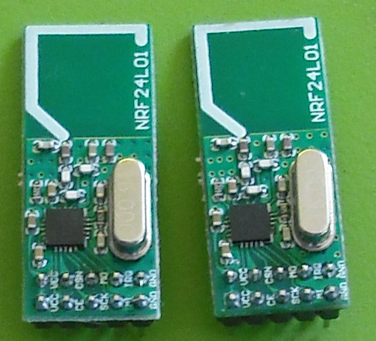
The PCBs with the zigzag shape
http://www.barefootelectronics.com/nordicc.png
are probably a "meandering inverted F antenna" similar to this one:
http://www.ti.com/lit/an/swra117d/swra117d.pdf
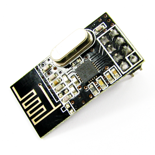
The PCBs with the seven shaped antenna is probably just a 1/4 wave monopole bent to make it less sensitive to polarization?
http://www.barefootelectronics.com/NordicA.jpg
Hard to say what the rubber ducks use unless pulled apart. It's easy to just assume they are all interchangeable. They aren't - they are designed specifically for the frequency to be used. This one is a dipole with the associated doughnut radiation pattern:
-
There are all sorts of magical antenna shapes - a few examples here:
http://www.ti.com/lit/an/swra351a/swra351a.pdf
The PCBs with the zigzag shape
http://www.barefootelectronics.com/nordicc.png
are probably a "meandering inverted F antenna" similar to this one:
http://www.ti.com/lit/an/swra117d/swra117d.pdf
The PCBs with the seven shaped antenna is probably just a 1/4 wave monopole bent to make it less sensitive to polarization?
http://www.barefootelectronics.com/NordicA.jpg
Hard to say what the rubber ducks use unless pulled apart. It's easy to just assume they are all interchangeable. They aren't - they are designed specifically for the frequency to be used. This one is a dipole with the associated doughnut radiation pattern:
@a-lurker Nice post!
I can report that I changed the SMA antenna that came with the songle with a +8db gain 2.4ghz wlan antenna and the signal died out completly, I think I'll will dissect the original antenna just to look why the bigger one didnt work at all..
maybe that's your problem @clippermiami ? try the old module but with the working antenna.
-
@a-lurker Nice post!
I can report that I changed the SMA antenna that came with the songle with a +8db gain 2.4ghz wlan antenna and the signal died out completly, I think I'll will dissect the original antenna just to look why the bigger one didnt work at all..
maybe that's your problem @clippermiami ? try the old module but with the working antenna.
@Damme Possible. But now I have another problem, the USB port has died so I no longer have access to the Gateway :-) Yet another opportunity :-)
-
@a-lurker Nice post!
I can report that I changed the SMA antenna that came with the songle with a +8db gain 2.4ghz wlan antenna and the signal died out completly, I think I'll will dissect the original antenna just to look why the bigger one didnt work at all..
maybe that's your problem @clippermiami ? try the old module but with the working antenna.
@Damme said:
I can report that I changed the SMA antenna that came with the songle with a +8db gain 2.4ghz wlan antenna and the signal died out completly,
I don't know why it didn't work, but even it it had, I'd be wary of a +8db gain antenna in this application. The gain comes with the tradeoff of a narrower beam and more directionality, and for home automation I don't want that.
-
I have started building up lots of nodes and don't even use a cap any longer. The problem I had with reception is purely because long cables. now I'm using <2cm and have no problems at all.
-
I have started building up lots of nodes and don't even use a cap any longer. The problem I had with reception is purely because long cables. now I'm using <2cm and have no problems at all.
-
-
I posted about this earlier but I think it was lost.
Disclaimer: I am no expert but this seems to be working for me... I have been experimenting with adding a wire to my regular nRF24L01 radio chips. I have the chips with the zig zag patteren. Based on some limited reading the wavelength is of 2.4 GHz is 4.92 inches (http://www.antenna-theory.com/definitions/2p4GHzAntenna.php). I did some rough measurements of the zig zag pattern with micrometer and found that the length is about 1.64 inches. So, based on that I soldered a 3.28 inch piece of CAT5e to the end of the zig zag pattern.
I had a new node that I installed on Sunday night that wasn't communicating with the gateway at all. I replaced the nRF24L01 with my modified one on Monday night and it has been communicating perfectly all night.
I should probably note that my new node had the radio zig zag pattern parallel to the ground which may have also caused some of the communication problems. I wasn't able to easily move the orientation because of how it was mounted, so the antenna was a quick test that appears to have solved the problem.
I have another node in which I have achieved similar results in a totally different part of my house.
Note: this also seems to be working for other people. See the comments of this blog post:http://harizanov.com/2013/06/nrf24l01-range-testing/
Based on the above post the PA+SMA antenna still has better range, but the CAT5 hack is much cheaper :)
I'd be interested to hear if this works for anyone else.
Pete
@petewill
I'm glad you resurfaced that lost discussion.Did you take a look at the references posted by @a-lurker about magical antenna shapes? A device similar to the zig-zag nRF was well measured in different planes and polarization and it'a all over the board - peaks and nulls in all sorts of directions.
But the zigzag isn't a random thing, it's carefully computed for a given wavelength and impedance. When you are bending and splitting and changing trace widths, the linear length for best matching is no longer as simple to compute as with a simple wire antenna. It's not that they forgot to add the last 3.28 inches, it's that their computations told them they had already reached a good compromise for coverage and making it longer would make it worse.
It's still surprising that soldering a loose wire to some location along the zig-zag so substantially improved your antenna performance. I still suspect some luck was involved, and I would not suggest it unless other solutions didn't work or were not available (eg: changing the antenna orientation). But if it works sometimes (not rarely), then it's useful on the practical level (and a fun puzzle on the theoretic level).
And I'd love to hear the take that better antenna experts than I have on your experience.
I am reminded of my youth, when people would hang aluminum foil fragments on the coat hanger substituting for the broken half of rabbit ears for the TV, and then try all sorts of positions for both ears, seeking better reception. :-) To the degree that this worked (vs just giving a perception of doing something) it was based on doing all that random adjustment while watching the picture and stopping in the best configuration.
-
@petewill
I'm glad you resurfaced that lost discussion.Did you take a look at the references posted by @a-lurker about magical antenna shapes? A device similar to the zig-zag nRF was well measured in different planes and polarization and it'a all over the board - peaks and nulls in all sorts of directions.
But the zigzag isn't a random thing, it's carefully computed for a given wavelength and impedance. When you are bending and splitting and changing trace widths, the linear length for best matching is no longer as simple to compute as with a simple wire antenna. It's not that they forgot to add the last 3.28 inches, it's that their computations told them they had already reached a good compromise for coverage and making it longer would make it worse.
It's still surprising that soldering a loose wire to some location along the zig-zag so substantially improved your antenna performance. I still suspect some luck was involved, and I would not suggest it unless other solutions didn't work or were not available (eg: changing the antenna orientation). But if it works sometimes (not rarely), then it's useful on the practical level (and a fun puzzle on the theoretic level).
And I'd love to hear the take that better antenna experts than I have on your experience.
I am reminded of my youth, when people would hang aluminum foil fragments on the coat hanger substituting for the broken half of rabbit ears for the TV, and then try all sorts of positions for both ears, seeking better reception. :-) To the degree that this worked (vs just giving a perception of doing something) it was based on doing all that random adjustment while watching the picture and stopping in the best configuration.
@Zeph Yeah, I'm definitely open to the possibility of dumb luck. I feel that's how I've built my whole sensor network. :) I hope that I will get a better understanding of things as I keep learning but for now it is mostly trial and error.
I have a feeling the bad signal could probably have been corrected by changing the orientation of the radio but soldering one wire was MUCH faster so I thought I'd give it a shot. It has been working flawlessly since I made that change. Luck or whatever, I'm happy... :)
-
@petewill
I'm glad you resurfaced that lost discussion.Did you take a look at the references posted by @a-lurker about magical antenna shapes? A device similar to the zig-zag nRF was well measured in different planes and polarization and it'a all over the board - peaks and nulls in all sorts of directions.
But the zigzag isn't a random thing, it's carefully computed for a given wavelength and impedance. When you are bending and splitting and changing trace widths, the linear length for best matching is no longer as simple to compute as with a simple wire antenna. It's not that they forgot to add the last 3.28 inches, it's that their computations told them they had already reached a good compromise for coverage and making it longer would make it worse.
It's still surprising that soldering a loose wire to some location along the zig-zag so substantially improved your antenna performance. I still suspect some luck was involved, and I would not suggest it unless other solutions didn't work or were not available (eg: changing the antenna orientation). But if it works sometimes (not rarely), then it's useful on the practical level (and a fun puzzle on the theoretic level).
And I'd love to hear the take that better antenna experts than I have on your experience.
I am reminded of my youth, when people would hang aluminum foil fragments on the coat hanger substituting for the broken half of rabbit ears for the TV, and then try all sorts of positions for both ears, seeking better reception. :-) To the degree that this worked (vs just giving a perception of doing something) it was based on doing all that random adjustment while watching the picture and stopping in the best configuration.
@Zeph a zigzag with 10dB and mesured 2 km range: Long range RF link using NRF24L01+ RF Transceiver
-
Hello guys!
I am no expert at antennas but I realize some of you have really bad reception.
I got ~450 meters between my nrf24l01+ap and a regular nrf24l01, and this through the house (concrete + wood) and through a forest.
There are some things to take in count;
Antenna orientation, if your gateway (with external antenna) is pointing straight up you have a vertical polarization of your transmission, this basically means that your nodes will work best if they also are vertical.
The radiation-pattern from the external antenna looks like this: http://commons.wikimedia.org/wiki/File:Short_dipole_radiation_pattern.gif
This means in a ideal location with no walls and you were floating in space you basically don't have any reception at all straight above or below the gateway. but since radio waves also reflect from objects you just have very poor reception in the real world.
And looking at the radiation-pattern you'll see that you have the best reception in the blue circles. (and the antennas on your internet router should be pointing straight up if you dont have a multi floor building.)
And because the radio waves reflect, the distance to cables, metal and ground-plane on a pcb matters a lot, if you have wrong distance, you can cancel out the signal almost completely, and you could actually amplify the signal in one direction by having the correct distance. (1/2 wave length = ~61mm if I'm not totally lost today) This is how parabolics works.
Well this is just a very short beginners knowledge and please, correct me and fill in missing facts. I just wanted to get the topic started.. :)
//Damme
Lol
I just realized why my wlan-antenna didn't work..:+1: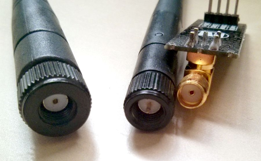
-
Hello guys!
I am no expert at antennas but I realize some of you have really bad reception.
I got ~450 meters between my nrf24l01+ap and a regular nrf24l01, and this through the house (concrete + wood) and through a forest.
There are some things to take in count;
Antenna orientation, if your gateway (with external antenna) is pointing straight up you have a vertical polarization of your transmission, this basically means that your nodes will work best if they also are vertical.
The radiation-pattern from the external antenna looks like this: http://commons.wikimedia.org/wiki/File:Short_dipole_radiation_pattern.gif
This means in a ideal location with no walls and you were floating in space you basically don't have any reception at all straight above or below the gateway. but since radio waves also reflect from objects you just have very poor reception in the real world.
And looking at the radiation-pattern you'll see that you have the best reception in the blue circles. (and the antennas on your internet router should be pointing straight up if you dont have a multi floor building.)
And because the radio waves reflect, the distance to cables, metal and ground-plane on a pcb matters a lot, if you have wrong distance, you can cancel out the signal almost completely, and you could actually amplify the signal in one direction by having the correct distance. (1/2 wave length = ~61mm if I'm not totally lost today) This is how parabolics works.
Well this is just a very short beginners knowledge and please, correct me and fill in missing facts. I just wanted to get the topic started.. :)
//Damme
I did some testing and analyzing of my microwave RF band.. (hehe)
Channel 76 which is 2476Mhz. and is between wlan channel 13 and 14.
My microwave oven destroys channel 7 - 13 almost completely (2462 - 2472) and affects 6 and 14 too. so a total of 2437 - 2484 mhz is mangled up (Surprises me a bit. And this is no cheap brand, its a quality micro wave, and the cheap one I have in the trash is even worse..)Me myself uses wlan 802.11n (40mhz channels) on ch1. so freq 2400 - 2442 is full also., so the best choice is actually using nrf24 channel above ch 85 in my case (and probobly others too). Could be good to know in future choice of default channel.
-
@Damme Just wondering, how did you analyze your 2.4 GHz band?
Here I read the typical levels of radiation leakage from microwave ovens is about 0.2 mW/cm², which is roughly equivalent to a point source of 6 dBm.
Is your microwave oven maybe leaking? According to this site you can test it placing your laptop in the microwave oven, close the door ... (do not turn the microwave on) and see if you can still ping it ;-)
@daulagari I had the chance of borrowing a hand held RF spectrum analyzer for a very short while (2h) I would love to do some more scientific measurements on all my transmitting apparatus.. :)
Hello! It looks like you're interested in this conversation, but you don't have an account yet.
Getting fed up of having to scroll through the same posts each visit? When you register for an account, you'll always come back to exactly where you were before, and choose to be notified of new replies (either via email, or push notification). You'll also be able to save bookmarks and upvote posts to show your appreciation to other community members.
With your input, this post could be even better 💗
Register Login