💬 Easy/Newbie PCB for MySensors
-
mmmm i think that al this work, for a 4 weeks working sensor is not a good solution for a home automation system....
Why can a Zwave or 433Mhz motion sensor work for more then a year...
Is my biggest question..
Forum linkIs there relay now solution for a battery live for a year...
Other bord, other sketch, other regulator, other battery...or...
Domoticz, with a lot of working hardware, include mysensors :-)
OpenPLI, RuneAudio, Solarmeter, etc......Not a great builder of software and hardware, more a user...
Only i try to do my best :-( -
mmmm i think that al this work, for a 4 weeks working sensor is not a good solution for a home automation system....
Why can a Zwave or 433Mhz motion sensor work for more then a year...
Is my biggest question..
Forum linkIs there relay now solution for a battery live for a year...
Other bord, other sketch, other regulator, other battery...or...
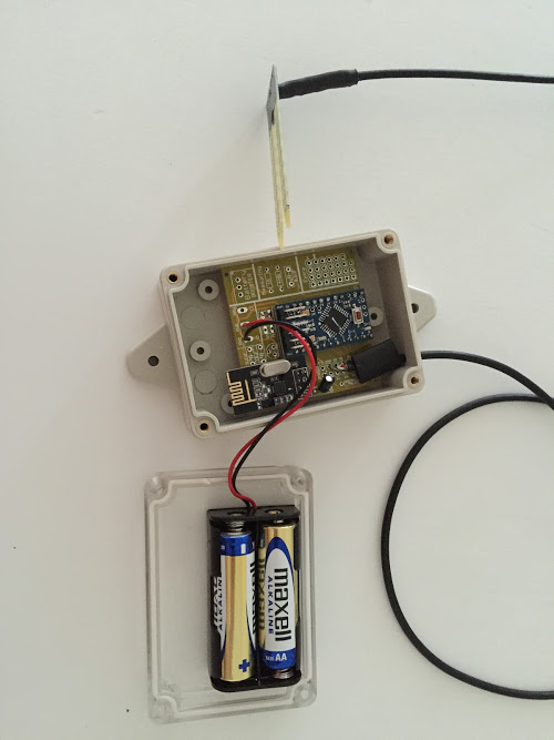
@Dylano Google for low power arduino mini. Or arduino mini on battery. I've got one running now for half a year on two aaa batteries. Only lost 10% or something.
(Quickest is to remove the led and the voltage regulator) -
@Dylano Im not sure if I understand what you mean. This PCB does not support 433mhz or Zwave. You need to make that a question in the forum. I have nodes with this PCB now almost running for a year, and reporting good battery level.
As Sander told you above, remove led and voltage regulator on a 3.3v arduino and you will run a mysensor node for a year:

-
This post is deleted!
-
This post is deleted!
@Sander-Teunissen I have some rev6 that I am willing to sell. Let me know if you are interested.
-
@Dylano Im not sure if I understand what you mean. This PCB does not support 433mhz or Zwave. You need to make that a question in the forum. I have nodes with this PCB now almost running for a year, and reporting good battery level.
As Sander told you above, remove led and voltage regulator on a 3.3v arduino and you will run a mysensor node for a year:
@sundberg84 said:
I have nodes with this PCB now almost running for a year, and reporting good battery level.
I see that battery measuring is not working in my case.
Can you post your sketch for a DHT22 or dallas sensor? Because readVCC.h does not work with a step up booster and 2x AA batteries connected, it seems.. -
@lxz This is my code (Note dev branch!) for DHT22 incl battery measuring (2xAA).
The reason for readVCC:h does not work is that you measure after the booster = always 3.3V!// Enable debug prints #define MY_DEBUG // Enable and select radio type attached #define MY_RADIO_NRF24 //#define MY_RADIO_RFM69 #define MY_NODE_ID 15 #include <SPI.h> #include <MySensor.h> #include <DHT.h> #define CHILD_ID_HUM 0 #define CHILD_ID_TEMP 1 #define HUMIDITY_SENSOR_DIGITAL_PIN 3 unsigned long SLEEP_TIME = 600000; // Sleep time between reads (in milliseconds) #define SKETCH_NAME "UtomhusHumSyd #15" // Change to a fancy name you like #define SKETCH_VERSION "1.0" // Your version DHT dht; float lastTemp; float lastHum; boolean metric = true; MyMessage msgHum(CHILD_ID_HUM, V_HUM); MyMessage msgTemp(CHILD_ID_TEMP, V_TEMP); //========================= // BATTERY VOLTAGE DIVIDER SETUP // 1M, 470K divider across battery and using internal ADC ref of 1.1V // Sense point is bypassed with 0.1 uF cap to reduce noise at that point // ((1e6+470e3)/470e3)*1.1 = Vmax = 3.44 Volts // 3.44/1023 = Volts per bit = 0.003363075 #define VBAT_PER_BITS 0.003363075 #define VMIN 1.9 // Vmin (radio Min Volt)=1.9V (564v) #define VMAX 3.0 // Vmax = (2xAA bat)=3.0V (892v) int batteryPcnt = 0; // Calc value for battery % int batLoop = 0; // Loop to help calc average int batArray[3]; // Array to store value for average calc. int BATTERY_SENSE_PIN = A0; // select the input pin for the battery sense point //========================= void setup() { analogReference(INTERNAL); // For battery sensing delay(500); // Allow time for radio if power used as reset dht.setup(HUMIDITY_SENSOR_DIGITAL_PIN); metric = getConfig().isMetric; } void presentation() { // Send the Sketch Version Information to the Gateway // Send the Sketch Version Information to the Gateway sendSketchInfo(SKETCH_NAME, SKETCH_VERSION); // Register all sensors to gw (they will be created as child devices) present(CHILD_ID_HUM, S_HUM); present(CHILD_ID_TEMP, S_TEMP); } void loop() { delay(500); // Allow time for radio if power used as reset delay(dht.getMinimumSamplingPeriod()); // Fetch temperatures from DHT sensor float temperature = dht.getTemperature(); if (isnan(temperature)) { Serial.println("Failed reading temperature from DHT"); } else if (temperature != lastTemp) { lastTemp = temperature; if (!metric) { temperature = dht.toFahrenheit(temperature); } send(msgTemp.set(temperature, 1)); Serial.print("T: "); Serial.println(temperature); } // Fetch humidity from DHT sensor float humidity = dht.getHumidity(); if (isnan(humidity)) { Serial.println("Failed reading humidity from DHT"); } else if (humidity != lastHum) { lastHum = humidity; send(msgHum.set(humidity, 1)); Serial.print("H: "); Serial.println(humidity); } batM(); sleep(SLEEP_TIME); //sleep a bit } void batM() //The battery calculations { delay(500); // Battery monitoring reading int sensorValue = analogRead(BATTERY_SENSE_PIN); delay(500); // Calculate the battery in % float Vbat = sensorValue * VBAT_PER_BITS; int batteryPcnt = static_cast<int>(((Vbat-VMIN)/(VMAX-VMIN))*100.); Serial.print("Battery percent: "); Serial.print(batteryPcnt); Serial.println(" %"); // Add it to array so we get an average of 3 (3x20min) batArray[batLoop] = batteryPcnt; if (batLoop > 2) { batteryPcnt = (batArray[0] + batArray[1] + batArray[2] + batArray[3]); batteryPcnt = batteryPcnt / 3; if (batteryPcnt > 100) { batteryPcnt=100; } Serial.print("Battery Average (Send): "); Serial.print(batteryPcnt); Serial.println(" %"); sendBatteryLevel(batteryPcnt); batLoop = 0; } else { batLoop++; } }``` -
Hi
I also bought v8 of these boards. 2 sensors up an running perfect.
2 others modules on the other hand, I think I fried the arduino. I am using 5v mini's. They worked when programming thru the USB port. Also communication with domoticz. They stopped working when I attached the 6v external adapter. I connected these to the ground and power connector. Now lights go on, but nothing anymore also not on the serial monitor.
Should I have used the raw connector????
thanks for helping
-
Short answer - yes you should have used RAW. But at least you learned a lesson if you want to think positive. ☺
Try and see what happens if you change. Maybe they are still OK.
-
what size terminal blocks do you buy? I bought some and they are the wrong size.
-
what size terminal blocks do you buy? I bought some and they are the wrong size.
@scooter217, from a quick inspection of the .brd file and a look around the internet for the datasheets it would seem that sundberg has allowed for any screw terminal block that uses a 5mm pin pitch. So you would need a 3 terminal 5mm pin pitch screw terminal. Please allow @sundberg84 some time to reply to ensure I am correct.
-
@scooter217 : http://www.ebay.com/sch/sis.html?_nkw=20pcs+KF301-2P+2+Pin+Plug-in+Screw+Terminal+Block+Connector+5.08mm+Pitch&_id=181759858196&&_trksid=p2057872.m2749.l2658
Controller: Proxmox VM - Home Assistant
MySensors GW: Arduino Uno - W5100 Ethernet, Gw Shield Nrf24l01+ 2,4Ghz
MySensors GW: Arduino Uno - Gw Shield RFM69, 433mhz
RFLink GW - Arduino Mega + RFLink Shield, 433mhz -
@sundberg84 Thank you, just ordered some from ebay!
-
Hi Sundberg.
First of all thanks for what you have done here, and hi from New Zealand.
I have a problem though, sorry to be a hassle.
I assembled my first board tonight and I dont get 3.3v across the NRF. It starts at 0.07V then falls down to 0 on my cheap meter. Same on the MYSX1.4 connector at 3.3 and gnd. Am getting 3.3 on the mini as well as VCC and GND on the MYSX area so the regulator is working. May be a short? Or a bad solder? Although they look good to me.... If so what solder joints should I redo? Any other ideas?
Also, Ive traced back the VCC from the NRF and I cant see where it connects to a power source, either the battery in or the boost converter?
Thanks,
Matt -
Hi Sundberg.
First of all thanks for what you have done here, and hi from New Zealand.
I have a problem though, sorry to be a hassle.
I assembled my first board tonight and I dont get 3.3v across the NRF. It starts at 0.07V then falls down to 0 on my cheap meter. Same on the MYSX1.4 connector at 3.3 and gnd. Am getting 3.3 on the mini as well as VCC and GND on the MYSX area so the regulator is working. May be a short? Or a bad solder? Although they look good to me.... If so what solder joints should I redo? Any other ideas?
Also, Ive traced back the VCC from the NRF and I cant see where it connects to a power source, either the battery in or the boost converter?
Thanks,
Matt@Matt Hi Matt - tnx.
Try to measure here: whats your reading?
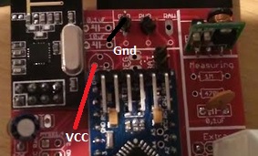
if its 3.3v its your radio thats has some error... this is prettu much the last point before radio. Also measure VCC/GND under the pcb and not on top, what does it say?Sounds like a short or bad solder...
-
@Matt Hi Matt - tnx.
Try to measure here: whats your reading?
if its 3.3v its your radio thats has some error... this is prettu much the last point before radio. Also measure VCC/GND under the pcb and not on top, what does it say?Sounds like a short or bad solder...
@sundberg84
Ah crikey I think Im being thick, I just put a jumper across BAT connectors after tracing the lines and reading the manual, am now getting 2.8 at the NRF. Sorry for being a numpty. Still not picking up on my gateway, time to go to bed but will get the serial monitor running tomorrow....
Thanks for the quick reply. -
I have a question about using this board as a gateway. Pinout of Mini Pro and Nano are almost identical. I built an adapter board to plug in a Nano into this board. Pin by pin control shows it is OK. I checked connectivity with MYSController. The gateway boots up. When I turn on my battery powered sensor, it asks for ID, the gateway "supposedly" sends it. I watch this from the messages. The sensor does not register. It asks four more times, the gateway responds four times. But sensor could not be ID'd and of course registered.
I am thinking either reception problem on sensor side, or transmission problem on gateway side? Could it be a power problem related with design of the board? Is there any way to identify?
Thanks