💬 Easy/Newbie PCB for MySensors
-
I have seen these boost/buck converters https://www.aliexpress.com/store/product/5pcs-mini-1-8V-3V-3-7V-5V-to-3-3V-Boost-Buck-Low-Noise-Regulated/1525466_32365767349.html
Would they make any sense to use with LiPo batteries or other solar power source to power a node? Or would they waste too much energy?
-
At least according to the specs, mcp1700 will do the trick (both in terms of drop out voltage and low power consumption for battery usage). I will try it.
Regarding the MCP1700 as a regulator (I ordered these: https://www.aliexpress.com/item/5-pcs-MCP1700-3302E-TO-MCP1700-Fixed-LDO-Voltage-Regulator/32781100568.html)
first connected the LIPO->TP4056->MCP1700 to the GND and PWR of the board. (I made a homemade little regulator board). From all appearances, it works great, and I end up with a nice compact sensor/battery. But I want to make use of the Easy/Newbie board. I tried hooking it up to the 3 pins marked regulator, but it didn't seem to do anything. Am I missing something? The orientation can be confusing, but I think I got it right. I measured 4.1 volts to the radio, which will fry it.
Thanks!
-
Regarding the MCP1700 as a regulator (I ordered these: https://www.aliexpress.com/item/5-pcs-MCP1700-3302E-TO-MCP1700-Fixed-LDO-Voltage-Regulator/32781100568.html)
first connected the LIPO->TP4056->MCP1700 to the GND and PWR of the board. (I made a homemade little regulator board). From all appearances, it works great, and I end up with a nice compact sensor/battery. But I want to make use of the Easy/Newbie board. I tried hooking it up to the 3 pins marked regulator, but it didn't seem to do anything. Am I missing something? The orientation can be confusing, but I think I got it right. I measured 4.1 volts to the radio, which will fry it.
Thanks!
@ileneken3 - the board is created for Le33a voltage regulator which has a different pinout than yours.
You have to adjust to that and not just put it in according to the pcb.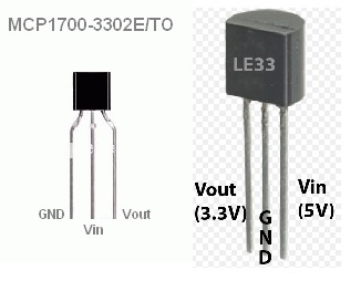
Controller: Proxmox VM - Home Assistant
MySensors GW: Arduino Uno - W5100 Ethernet, Gw Shield Nrf24l01+ 2,4Ghz
MySensors GW: Arduino Uno - Gw Shield RFM69, 433mhz
RFLink GW - Arduino Mega + RFLink Shield, 433mhz -
@ileneken3 - the board is created for Le33a voltage regulator which has a different pinout than yours.
You have to adjust to that and not just put it in according to the pcb.@sundberg84
I did adjust to the different pinout. I checked it multiple times, checked soldering - it always seems like the regulator is not regulating anything - the radio always gets 4.1 volts from the LIPO.
From looking at the specs, the LE33 is pretty close - with the biggest difference that the MCP1700 can handle more current.
Maybe I should just get the LE33 ones.Oh well...
-
@sundberg84
I did adjust to the different pinout. I checked it multiple times, checked soldering - it always seems like the regulator is not regulating anything - the radio always gets 4.1 volts from the LIPO.
From looking at the specs, the LE33 is pretty close - with the biggest difference that the MCP1700 can handle more current.
Maybe I should just get the LE33 ones.Oh well...
@ileneken3 your problem with le33 will be the quiescent current which is high, datasheet says "typ. 50 μA in OFF
mode, 0.5 mA in ON mode, no load". 0.5mA will not give you a good battery life...
Compared to a typical value of 1.6µA on the MCP1700 (max at 4µA), you should stick to it if you are using a battery.Did you test the MCP1700 on a breadboard ?
-
@sundberg84
I did adjust to the different pinout. I checked it multiple times, checked soldering - it always seems like the regulator is not regulating anything - the radio always gets 4.1 volts from the LIPO.
From looking at the specs, the LE33 is pretty close - with the biggest difference that the MCP1700 can handle more current.
Maybe I should just get the LE33 ones.Oh well...
@ileneken3 Can you post a pic showing how you have this wired? preferably the side where your battery is connected. I would like to see where you have your battery connected and how you have the board wired.
-
@ileneken3 your problem with le33 will be the quiescent current which is high, datasheet says "typ. 50 μA in OFF
mode, 0.5 mA in ON mode, no load". 0.5mA will not give you a good battery life...
Compared to a typical value of 1.6µA on the MCP1700 (max at 4µA), you should stick to it if you are using a battery.Did you test the MCP1700 on a breadboard ?
Yes, I agree. I didn't look closely enough at the currents for le33. The general rule of thumb seems to be:
Current in "milli"amps -> only days or weeks for a battery
Current in "micro"amps -> months on a batterySo MCP1700 seems to be right for a LIPO here.
I did test it on a breadboard. And then I built a little regulator board. It works great.. and I used a battery from an old cell phone that stills seems to work well.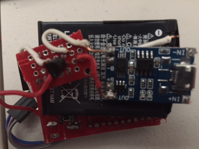
-
@ileneken3 Can you post a pic showing how you have this wired? preferably the side where your battery is connected. I would like to see where you have your battery connected and how you have the board wired.
There's not much to the wiring (maybe that's my problem?).
To attach the legs to be like a LE33, I swung the Vout of the MCP1700 all the way to the left.
With a multimeter, I see 4.1 volts at the radio, and everywhere else.
Thanks!
-
There's not much to the wiring (maybe that's my problem?).
To attach the legs to be like a LE33, I swung the Vout of the MCP1700 all the way to the left.
With a multimeter, I see 4.1 volts at the radio, and everywhere else.
Thanks!
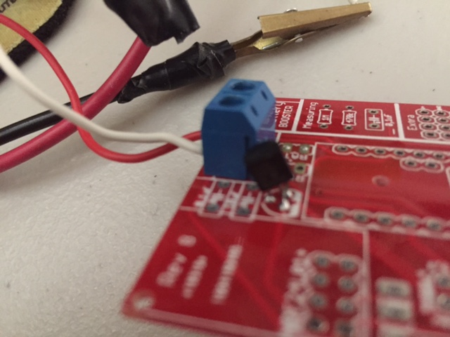
@ileneken3 OK, I think I see the issue. I think you need a jumper across the reg pads just to the right of the regulator. If you check with a volt meter between the regulator's V-In and the bottom reg pad, you should get continuity. Then if you check from the top reg pad to the positive lead of your battery, you should get continuity there also. you need to bridge that gap to get the power from your battery to the regulator.
You would also be wise to add the 0.1uf ceramic and 10uf electrolytic capacitors just above the regulator. The 0.1uf will filter the power coming in to the regulator, and the 10uf will filter the output of the regulator. The other capacitor not to forget is the 4.7uf electrolytic just below the nRF24 radio. If you forget that, you will surely have radio problems.
-
There's not much to the wiring (maybe that's my problem?).
To attach the legs to be like a LE33, I swung the Vout of the MCP1700 all the way to the left.
With a multimeter, I see 4.1 volts at the radio, and everywhere else.
Thanks!
@ileneken3 like @dbemowsk says you need capacitors (and probably a jumper) . The LDO will go into oscillation without capacitors.
-
There's not much to the wiring (maybe that's my problem?).
To attach the legs to be like a LE33, I swung the Vout of the MCP1700 all the way to the left.
With a multimeter, I see 4.1 volts at the radio, and everywhere else.
Thanks!
@ileneken3 - as mentioned the PCB is made generic so to activate the voltage regulation part (Power -> Volt Reg -> Radio) you need to add a jumper for REG. If one want to bypass the voltage regulation part you jump BAT (and use the booster instead). Have a look at the instructions here and let me know if you think something is missing. The capacitors for the voltage regulator are also recommended as mentioned.
In your case with 4.2 volts, BAT will give you 4.2 volts on the radio and nothing more (if you dont jump the booster as well) and REG will give you 4.2 volts to the arduino and sensors and the regulated voltage to the radio.
It looks like you used BAT in the pictures? If you didnt solder any BAT/REG you should not get anything. Dont solder both!
-
OK, looks like I had multiple problems.
I somehow missed the instructions about "don't solder both", and was also slightly confused about the directions because I am using a battery (LIPO), but following the "5V regulated" instructions. When the instructions mention battery, it always mean a 3.3V battery. I had the BAT jumpered, and then I tried with and without the REG jumpered.
At the same time, I believe I damaged the MCP1700 regulator - I will have to take it off and test it.
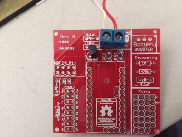
So in the interest of getting this resolved quickly, I started all over again with a new board, new regulator, and jumping only REG. It worked! Here is the picture: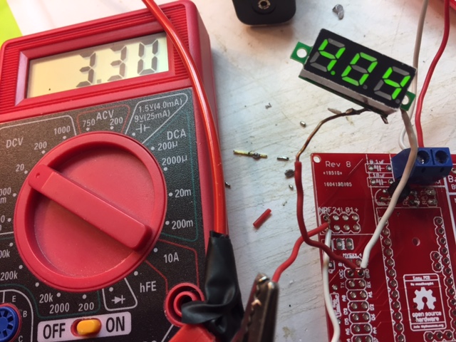
You can see that the radio will get 3.3V, and the rest of the board will get 4+ volts. (The TP4056 will cut it off as it goes down to around 3V).
So I will continue the build, and if everything goes according to spec, the radio, arduino, and sensors should all be OK. (Assuming the sensor can handle 4+ volts).
As far as the capacitors, it looks like the spec says 1uF on input and output. So I will put those where there are labels for .1 and 10uF. For the radio, I am well aware of its capacitor needs (learning the hard way). At this point, I always put the 4.7uF cap directly on the radio.
If everything goes well, I would recommend putting some sort of reference to LIPO batteries in the instructions. I couldn't be the only one who wants to do this.
Great support from everyone!
-
I am also looking at using lipo batteries, but I've been told they have a tendency to self discharge over time, so normal AA batteries or cr123 provide longer battery life of course if the node is not power hungry
@gohan - I can't and wont throw figures around here concerning how much they discharge per day, but they do indeed self-discharge and in my opinion wouldn't be suitable for a sleeping node.
MySensors 2.1.1
Controller - OpenHAB (Virtual Machine)
Gateway - Arduino Mega MQTT Gateway W5100 -
@gohan - I can't and wont throw figures around here concerning how much they discharge per day, but they do indeed self-discharge and in my opinion wouldn't be suitable for a sleeping node.
@Samuel235
The key question here (at least for this forum subject), is "should you a LIPO with a Easy/Newbie PCB board"? My answer is "in some cases". For sure, the gold standard of sleeping nodes is 2 AA batteries that last over a year. It's best both in terms of price and longevity. But there are scenarios for using LIPO's:-
The AA batteries are too big. LIPO's come in all sizes, and the one from my old cell phone was nice and compact for a particular enclosure I wanted to use.
-
You have LIPO's lying around (like from an old laptop) and you just want to use them.
-
The sensors you are using are "power hungry" and you just can't find a way around it (and you can't plug it into the wall). Using a LIPO will avoid having to throw away a lot of AA's.
As far as discharge rate, from what I read it's not too bad (just not as good as AA's). With sensors that are not power hungry, and with the right voltage regulator (like a MCP1700), I am anticipating it lasting for months. At that point, it's not that big of a deal to recharge with that frequency.
For use with power hungry sensors (which may mean using just 2 ma), I am hoping for weeks.
I will continue with the experiment unless someone says I am way off in my estimations.
-
-
As requested a few images of the version 9 board, mounted for battery with some extra pin sockets while experimenting.
-
As requested a few images of the version 9 board, mounted for battery with some extra pin sockets while experimenting.
@jens-persson - Tnx, but hmmm.. I cant see them. Just a stop sign. Maybe my web-browser?
Controller: Proxmox VM - Home Assistant
MySensors GW: Arduino Uno - W5100 Ethernet, Gw Shield Nrf24l01+ 2,4Ghz
MySensors GW: Arduino Uno - Gw Shield RFM69, 433mhz
RFLink GW - Arduino Mega + RFLink Shield, 433mhz -
@jens-persson - Tnx, but hmmm.. I cant see them. Just a stop sign. Maybe my web-browser?
-
:-(
Thought the settings on the album should apply to the images also.
Here is a link to the album: https://goo.gl/photos/bX9HZSXdbMCvuyAv9
Does it work? -
:-(
Thought the settings on the album should apply to the images also.
Here is a link to the album: https://goo.gl/photos/bX9HZSXdbMCvuyAv9
Does it work?@jens-persson - It does! Nice images! Well done :+1:
I like you have added headers so you can add and remove quickly,.

