💬 Easy/Newbie PCB for MySensors
-
Hi,
I see you use CERN OHL but I do not find the required files.
Where do you store those?
According to the CERN OHL 1.2 howto, you need to provide the following documentation with your project:
LICENSE.PDF
cern_ohl_v_1_2_howto.pdf
PRODUCT.TXT
CHANGES.TXTPlease check the howto closely for how to use the license, or pick another license. If it is not used according to spec, others don't need to follow it either since it is invalid, so you won't be "protected" by it.
-
@sundberg84
Thanks for the explanation!
I think I've got it now.
Will test and get back with the results when I've gotten my hands on some more solder wire!@BastienVH
Replying to myself to follow up on my assembly-issues.
I have been able to get the board to work.
I don't have my 0.1µF caps yet, so I just put a little blob of solder in the holes so the current could run through.
Now I've got myself 2 working board. I just have to find a good way to attach my PIR, dallas temp, ... to them.Thanks for the work and help!
-
I'am now finnish with my first rev7 node.
It is a Arduino 5V with DHT-22 and a HC-SR501 sensor.
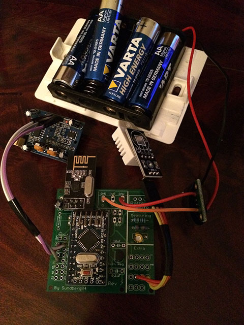
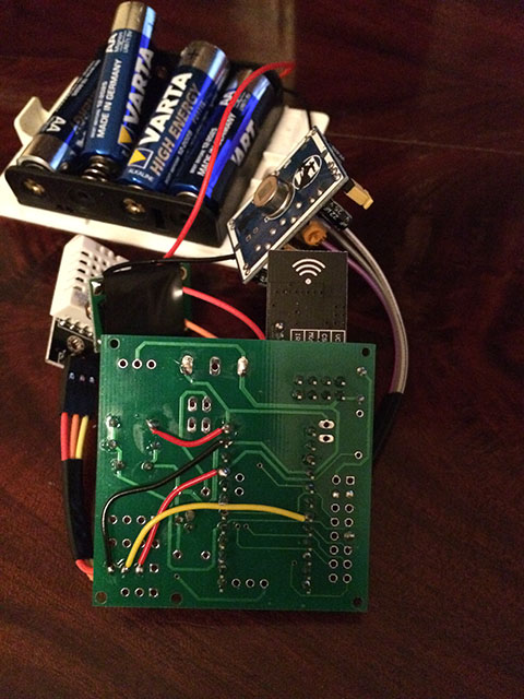
Good work @sundberg84 for the PCB
-
@BastienVH Good to hear - its not essential to have to 0.1uF cap on the voltage retulator, it will work without but its good to keep noice out.
@ErrK Nice, I see you run through RAW pin and using the internal voltage regulator on the arduino - I have not tested that much, does it work ok?Controller: Proxmox VM - Home Assistant
MySensors GW: Arduino Uno - W5100 Ethernet, Gw Shield Nrf24l01+ 2,4Ghz
MySensors GW: Arduino Uno - Gw Shield RFM69, 433mhz
RFLink GW - Arduino Mega + RFLink Shield, 433mhz -
@BastienVH Good to hear - its not essential to have to 0.1uF cap on the voltage retulator, it will work without but its good to keep noice out.
@ErrK Nice, I see you run through RAW pin and using the internal voltage regulator on the arduino - I have not tested that much, does it work ok?@sundberg84
When I get the caps, I'll place them on the board.
I did notice alot of noise when I was reading battery state on a breadboard in an earlier build, so I will get that sorted.
Only problem is I can't find them locally, so have to get them from China.
Will take a while... -
@BastienVH Good to hear - its not essential to have to 0.1uF cap on the voltage retulator, it will work without but its good to keep noice out.
@ErrK Nice, I see you run through RAW pin and using the internal voltage regulator on the arduino - I have not tested that much, does it work ok?@sundberg84 yes it's working good. But the problem is that it's eating up the batteries :)
It was up for only 15days.I will now test with a arduino that i have removed the led and volt regulator.
-
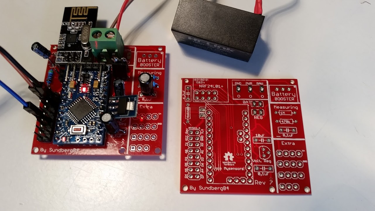
Sounds good @ErrK - dont forget to power it through REG and not RAW on the PCB and add a jumper on REG since it wont work if you use the same setup as in the images and remove voltage regulator.
Controller: Proxmox VM - Home Assistant
MySensors GW: Arduino Uno - W5100 Ethernet, Gw Shield Nrf24l01+ 2,4Ghz
MySensors GW: Arduino Uno - Gw Shield RFM69, 433mhz
RFLink GW - Arduino Mega + RFLink Shield, 433mhz -
Sounds good @ErrK - dont forget to power it through REG and not RAW on the PCB and add a jumper on REG since it wont work if you use the same setup as in the images and remove voltage regulator.
Thank you @sundberg84. I will think of that.
-
@Barna - I just wanted to make it smaller, with the radio not sticking out so much.
I ordered them a while ago, so if they made it out of china before their new year I think it will be tested soon. -
Nice. @dark-nico
The main concern is the new placement of caps and voltage divider - I hope they fit in between the radio and screw terminal. Should not be a problem - but you know, always nice to see it IRL. Might be good to solder them first before radio, arduino and screw terminal. -
Ok, I'll do that.
My main problem is that I haven't received both my booster and my 5->3.3 reg. :disappointed:
So I can test Batt version by bypassing the booster, but it will not tell us if the reg placement is ok.
I'll dig in my "donor harware" if I can find a reg. -
@dark-nico - You know its easy to cut the PCB to make it smaller? Using it as 5v you can remove the right battery part:
Either cut with a knife and brake:
https://www.youtube.com/watch?v=SiC-_g3iNb8Or sometimes i just use a saw (before components are added) - might not be recommended ;)
Controller: Proxmox VM - Home Assistant
MySensors GW: Arduino Uno - W5100 Ethernet, Gw Shield Nrf24l01+ 2,4Ghz
MySensors GW: Arduino Uno - Gw Shield RFM69, 433mhz
RFLink GW - Arduino Mega + RFLink Shield, 433mhz -
@dark-nico - You know its easy to cut the PCB to make it smaller? Using it as 5v you can remove the right battery part:
Either cut with a knife and brake:
https://www.youtube.com/watch?v=SiC-_g3iNb8Or sometimes i just use a saw (before components are added) - might not be recommended ;)
@sundberg84 - Yes I know that I can cut that part, but I think this one will be my test board with all this option, including the battery parts.
However I'll keep the video method in mind, I was thinking about using a dremel, but, it seems cleaner. -
@dark-nico Ok, have not tested adding both Bat and reg/5v posibilities at the same time. Might be that 5v travels backwards towards the booster... try it out, but as I said, not tested.
-
@sundberg84 : I have also received the rev 7 from DirtyPCB and learned how to solder. Very nice and flexible design !
Perfect for a Newbie :). Thnaks a lot for sharing -
Hi!
No problems! Makes me glad to see i made something usefull for others :)
Interesting setup you got the with the HLK as power :+1: -

